Page 130 of 444
0-26
RODIUS 2007.07
0000-00
ENGINE GENERAL
▶Engine Compartment Layout
Engine assembly
Engine oil dipstick
Vacuum pump
Oil filter and cooler
Fuel filter and priming pump
Brake booster
Brake oil tank
AQGS unit
Washer fluid filler cap
Engine compartment fuse box
PTC relay box
Battery
Vacuum modulator (for VGT turbo charger) 1.
2.
3.
4.
5.
6.
7.
8.
9.
10.
11.
12.
13.FFH Assembly (Only for vehicle with FFH)
Power steering oil tank
Engine oil filler cap
Fan shroud
E-EGR Valve
High-capacity PCV oil separator
HFM sensor (6.0)
VGT turbo charger
Air cleaner housing
2Coolant surge tank
ABS/ESP HECU (Including TPMS function:
optional)
Exhaust gas FRT Temp. sensor (T3) 14.
15.
16.
17.
18.
19.
20.
21.
22.
23.
24.
25.
Page 169 of 444
0-7
ELECTRIC GENERAL
RODIUS 2007.07
0000-00
Sub condenser
Theft deterrent horn (under the washer fluid reservoir)
PTC power supply relay
(PTC system equipped vehicle)
ABS (ESP) HECU
(under the battery)
Fuse and relay box in engine compartmentBrake pressure sensor
Page 301 of 444
0-8
RODIUS 2007.07
4830-01
BRAKS SYSTEM
6) Master Cylider & Booster
ABS system is basically equipped to STAVIC.
Vehicle which adapted ESP system in option has two pressure sensors under master cylinder
and these two sensor are used for BAS (Brake Assist System) system.
Do not disassemble the brake oil pressure sensors These can not be reinstalled of
disassembled.
After reinstall the reserver tank perform a air bleeding of brake system
-
-
Vehicle with ESP Vehicle with ABS
Brake fluid reservoir tank Master cylinder
Page 305 of 444

0-6
RODIUS 2007.07
4892-01
ESP SYSTEM
3. ESP SYSTEM DESCRIPTION
1) Principle of ESP
ESP (Electronic Stability Program) recognizes critical driving conditions, such as panic
reactions in dangerous situations, and stabilizes the vehicle by wheel-individual braking and
engine control intervention with no need for actuating the brake. This system is developed to
help the driver avoid the danger of losing the control of the vehicle stability due to under-
steering or over-steering during cornering.
The yaw rate sensor, lateral sensor and longitudinal sensor in the sensor cluster and the
steering wheel angle sensor under the steering column detect the spin present at any wheels
during over-steering, under-steering or cornering. The ESP ECU controls against over-steering
or under-steering during cornering by controlling the vehicle stability using the input values from
the sensors and applying the brakes independently to the corresponding wheels.
The system also controls during cornering by detecting the moment right before the spin and
automatically limiting the engine output (coupled with the ASR system).
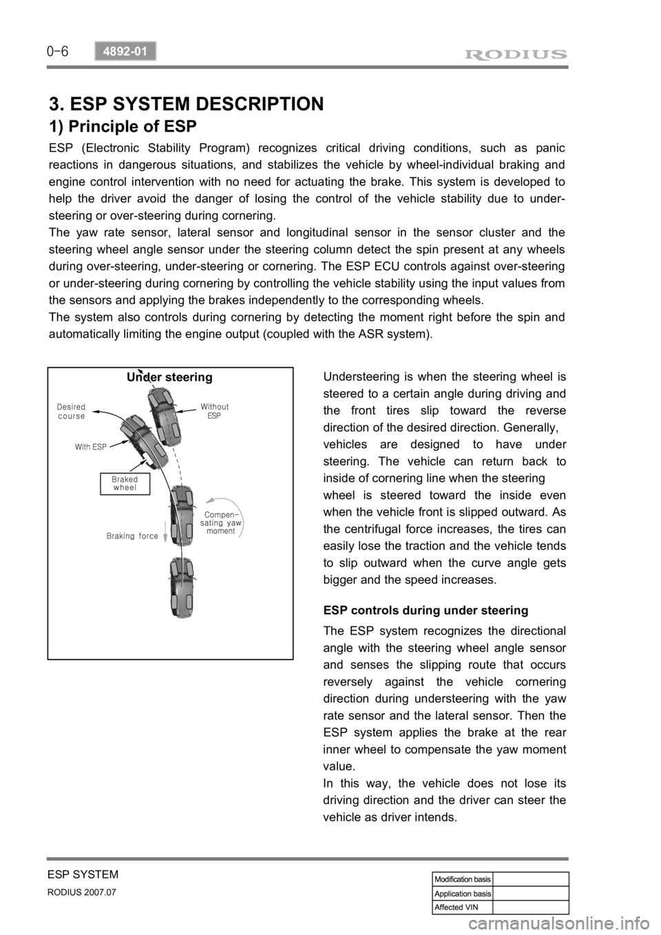
Understeering is when the steering wheel is
steered to a certain angle during driving and
the front tires slip toward the reverse
direction of the desired direction. Generally,
vehicles are designed to have unde
r
steering. The vehicle can return back to
inside of cornering line when the steering
wheel is steered toward the inside even
when the vehicle front is slipped outward.
As
the centrifugal force increases, the tires can
easily lose the traction and the vehicle tends
to slip outward when the curve angle gets
bigger and the speed increases. Under steering
ESP controls during under steering
The ESP system recognizes the directional
angle with the steering wheel angle senso
r
and senses the slipping route that occurs
reversely against the vehicle cornering
direction during understeering with the yaw
rate sensor and the lateral sensor. Then the
ESP system applies the brake at the rea
r
inner wheel to compensate the yaw moment
value.
In this way, the vehicle does not lose its
driving direction and the driver can steer the
vehicle as driver intends.
Page 306 of 444

0-7
ESP SYSTEM
RODIUS 2007.07
4892-01
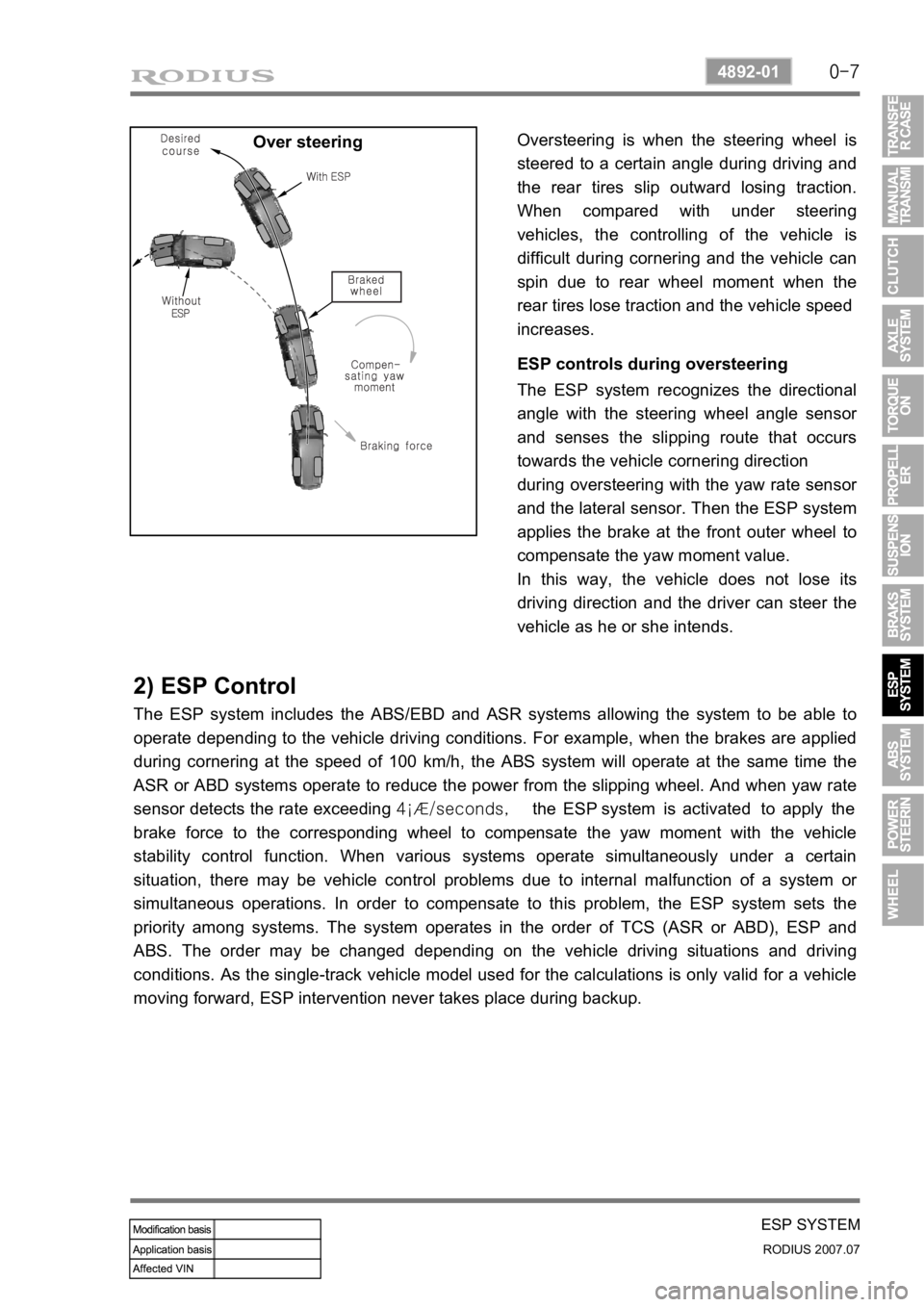
Over steeringOversteering is when the steering wheel is
steered to a certain angle during driving and
the rear tires slip outward losing traction.
When compared with under steering
vehicles, the controlling of the vehicle is
difficult during cornering and the vehicle can
spin due to rear wheel moment when the
rear tires lose traction and the vehicle speed
increases.
ESP controls during oversteering
The ESP system recognizes the directional
angle with the steering wheel angle senso
r
and senses the slipping route that occurs
towards the vehicle cornering direction
during oversteering with the yaw rate senso
r
and the lateral sensor. Then the ESP system
applies the brake at the front outer wheel to
compensate the yaw moment value.
In this way, the vehicle does not lose its
driving direction and the driver can steer the
vehicle as he or she intends.
2) ESP Control
The ESP system includes the ABS/EBD and ASR systems allowing the system to be able to
operate depending to the vehicle driving conditions. For example, when the brakes are applied
during cornering at the speed of 100 km/h, the ABS system will operate at the same time the
ASR or ABD systems operate to reduce the power from the slipping wheel. And when yaw rate
sensor detects the rate exceeding 4¡Æ/seconds, the ESP system is activated to apply the
brake force to the corresponding wheel to compensate the yaw moment with the vehicle
stability control function. When various systems operate simultaneously under a certain
situation, there may be vehicle control problems due to internal malfunction of a system o
r
simultaneous operations. In order to compensate to this problem, the ESP system sets the
priority among systems. The system operates in the order of TCS (ASR or ABD), ESP and
ABS. The order may be changed depending on the vehicle driving situations and driving
conditions. As the single-track vehicle model used for the calculations is only valid for a vehicle
moving forward, ESP intervention never takes place during backup.
Page 307 of 444

0-8
RODIUS 2007.07
4892-01
ESP SYSTEM
2) ESP Control
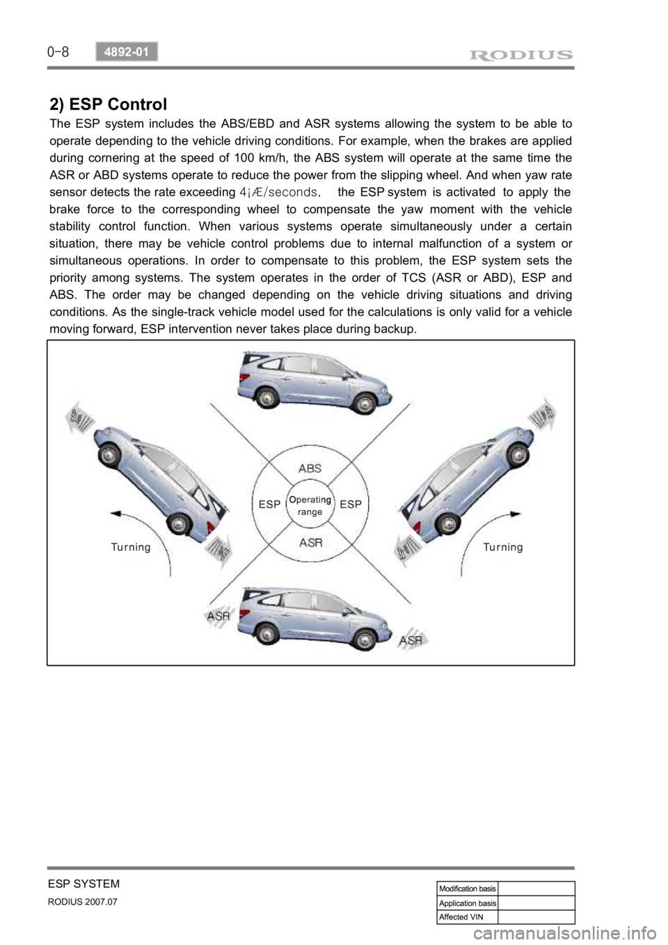
The ESP system includes the ABS/EBD and ASR systems allowing the system to be able to
operate depending to the vehicle driving conditions. For example, when the brakes are applied
during cornering at the speed of 100 km/h, the ABS system will operate at the same time the
ASR or ABD systems operate to reduce the power from the slipping wheel. And when yaw rate
sensor detects the rate exceeding 4¡Æ/seconds, the ESP system is activated to apply the
brake force to the corresponding wheel to compensate the yaw moment with the vehicle
stability control function. When various systems operate simultaneously under a certain
situation, there may be vehicle control problems due to internal malfunction of a system o
r
simultaneous operations. In order to compensate to this problem, the ESP system sets the
priority among systems. The system operates in the order of TCS (ASR or ABD), ESP and
ABS. The order may be changed depending on the vehicle driving situations and driving
conditions. As the single-track vehicle model used for the calculations is only valid for a vehicle
moving forward, ESP intervention never takes place during backup.
Page 309 of 444

0-10
RODIUS 2007.07
4892-01
ESP SYSTEM
4) HBA (Hydraulic Brake Assist System)
(1) Purpose
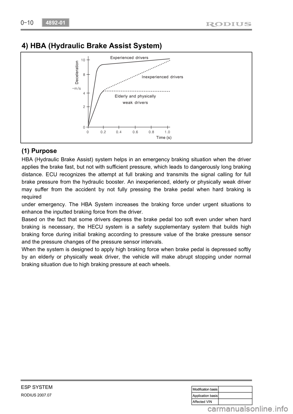
HBA (Hydraulic Brake Assist) system helps in an emergency braking situation when the driver
applies the brake fast, but not with sufficient pressure, which leads to dangerously long braking
distance. ECU recognizes the attempt at full braking and transmits the signal calling for full
brake pressure from the hydraulic booster. An inexperienced, elderly or physically weak drive
r
may suffer from the accident by not fully pressing the brake pedal when hard braking is
required
under emergency. The HBA System increases the braking force under urgent situations to
enhance the inputted braking force from the driver.
Based on the fact that some drivers depress the brake pedal too soft even under when hard
braking is necessary, the HECU system is a safety supplementary system that builds high
braking force during initial braking according to pressure value of the brake pressure senso
r
and the pressure changes of the pressure sensor intervals.
When the system is designed to apply high braking force when brake pedal is depressed softly
by an elderly or physically weak driver, the vehicle will make abrupt stopping under normal
braking situation due to high braking pressure at each wheels.
Page 310 of 444
0-11
ESP SYSTEM
RODIUS 2007.07
4892-01
(2) Operation
The brake pressure value and the changed value of the pressure sensor are the conditions in
which the HBA System operates. There are 2 pressure sensors under the master cylinder.
When the ESP ECU system determines that emergency braking is present, the pump operates,
the brake fluid in the master cylinder is sent to the pump and the braking pressure is delivered
to the wheels via the inlet valves.
If the drive depress the brake pedal slowly, the pressure change is not high. In this case, only
the conventional brake system with booster is activated.