Page 232 of 444
0-9
LAMP
RODIUS 2007.07
8310-01
4. Luggage room lamp
: one at center (12V - 5W)
Luggage room lamp is turned on
and off when the switch (1) is
pressed in and out.
Luggage lamp is turned on and of
f
when opening and closing one o
f
rear doors with the front room lamp
switch pressed in.
5. Glove box lamp
: one at center (12V - 5W)
6. Door courtesy lamp
: one at each door (12V - 5W)
Door courtesy lamp is turned on when
opening a door while the ignition switch
is in “ON” position.
Rear (third row set) room lamp
Rear (second row set) room lamp
Front room lamp
Glove box lamp
Center console lamp
Page 328 of 444

0-10
RODIUS 2007.07
4892-01
ABS SYSTEM
3. ON-VEHICLE SERVICE
(1) Electronic system service precautions
Take care to avoid electronic brake control module (HECU) circuit overloading. In testing for
opens or shorts, do not ground or apply voltage to any circuit unless instructed to do so by the
diagnostic procedure. Test circuits only with a high-impedance multi-meter. Never remove o
r
apply power to any control module with the ignition switch in the ON position. Always turn the
ignition to the OFF position before removing or connecting battery cables, fuses or connectors.
(2) General service precautions
Disconnect the HECU connector before performing any vehicle welding work using an electric
arc welder. Do not attempt to disassemble any component designated as nonserviceable. The
hydraulic modulator and the HECU can be seperated. (There is however no access to repai
r
the each components.)
(3) Bleeding system
Replacement modulators are shipped already filled and bled. In normal procedures requiring
removal of the modulator, such as to replace the HECU, air will not enter the modulator, and
normal bleeding will be all that is needed.
If air enters the hydraulic modulator, or if an unfilled modulator is installed, use the brake
bleeding program in the scan tool to bleed the modulator. Manual bleeding of the hydraulic
modulator is not possible.
1) Service Precautions
Brake Fluid may irritate eyes and skin. In case of contact, take the following actions:
Eye contact - rinse thoroughly with water.
Skin contact - wash with soap and water.
Ingestion - consult a physician immediately. -
-
-
To help avoid personal injury due to poor braking. DO NOT Tap into the vehicle’s
brake system to operate a trailer brake system.
When fasteners are removed, always reinstall them at the same location from which they
were removed. If a fastener needs to be replaced, use the correct part number fastener
for is not available, a fastener of equal size and strength (or stronger) may be used.
Fasteners that are not reused, and those requiring thread-locking compound will be
called out. The correct torque values must be used when installing fasteners that require
them. If the above procedures are not followed, parts or system damage could result.
Page 334 of 444

0-16
RODIUS 2007.07
4892-01
ABS SYSTEM
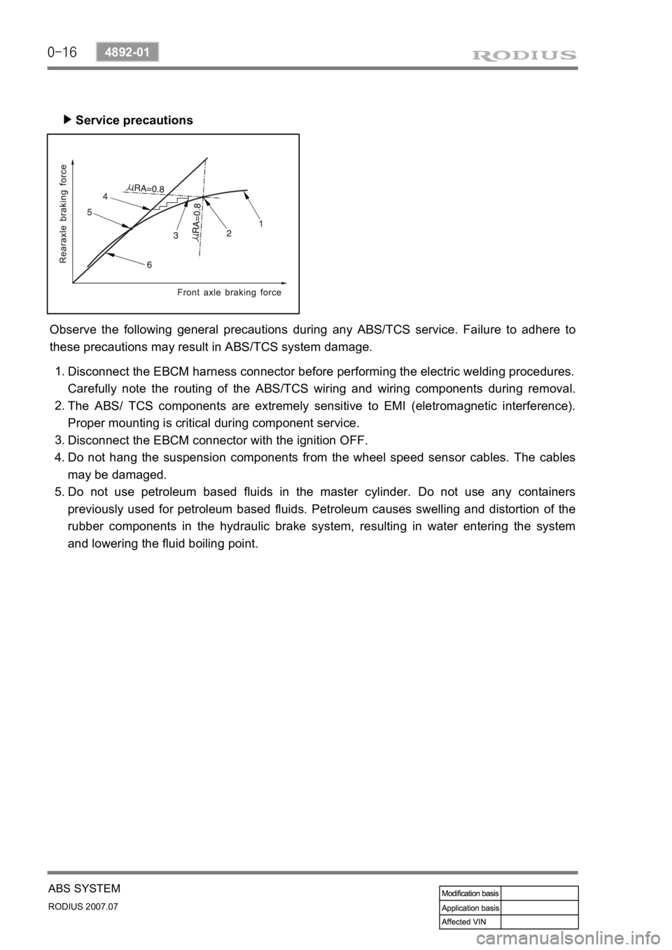
Service precautions ▶
Observe the following general precautions during any ABS/TCS service. Failure to adhere to
these precautions may result in ABS/TCS system damage.
Disconnect the EBCM harness connector before performing the electric welding procedures.
Carefully note the routing of the ABS/TCS wiring and wiring components during removal.
The ABS/ TCS components are extremely sensitive to EMI (eletromagnetic interference).
Proper mounting is critical during component service.
Disconnect the EBCM connector with the ignition OFF.
Do not hang the suspension components from the wheel speed sensor cables. The cables
may be damaged.
Do not use petroleum based fluids in the master cylinder. Do not use any containers
previously used for petroleum based fluids. Petroleum causes swelling and distortion of the
rubber components in the hydraulic brake system, resulting in water entering the system
and lowering the fluid boiling point. 1.
2.
3.
4.
5.
Page 364 of 444

0-13
AIR CONDITIONING SYSTEM
RODIUS 2007.07
6810-20
4. SENSORS AND ACTUATORS
1) Sun Sensor
It is installed on the upper left end of instrument panel. It is using characteristics that the
amount of current changes according to amount of light on the photosensitive surface. Photo
diode, converts the changes in light intensity into electrical changes, detects the amount of light
coming through windshield and changes it into current and then sends the signal to FATC
controller.
(1) Inspection
Remove the sun sensor and measure the current between terminals under sunlight.
Measure the current again under shade. It is in normal conditions if the measured value is
less than the measured value under sunlight.
Turn the ignition switch to “ON” position.
Measure the voltage to the sun sensor from FATC connector. (approx. 2.5 V under sunlight
and 4.8 V under shade.)
If the voltage value cannot be measured, check the circuit for open. If the measured value is
within the specified range, replace the FATC controller. 1.
2.
3.
4.
5.
Page 366 of 444
0-15
AIR CONDITIONING SYSTEM
RODIUS 2007.07
6810-20
(3) Inspection
If the active incar sensor defect code (DTC 1) and the humidity sensor defect code (DTC 10)
are set, check as below:
Air conditioner controller
Air conditioner controller connector (based on wiring) AIH sensor (based on sensor)
Active incar sensor
▶
Remove the integrated AIH sensor and measure the resistance between terminal No. 5 and
6 on the sensor connector. (standard: approx. 25°C, 2.2 kΩ)
If the measured value is out of the specified range, replace the AIH sensor. If the measured
values are within the specified range, check as below.
Turn the ignition switch to ON position and measure the voltage to active incar sensor from
the FATC controller connector. (standard: approx. 2 V at 25°C)
If the voltage value cannot be measured, check the circuit for open. If the measured value is
within the specified range, replace the FATC controller.
1.
2.
3.
4.
Page 371 of 444
![SSANGYONG RODIUS 2006 Service Manual 0-20
RODIUS 2007.07
6810-20
AIR CONDITIONING SYSTEM
3) AQS Operation Circuit
1. Ambient temperature switch
2. Sensor ground
3. AQS signal (Output)
4. Ground
5. IGN 2
[AQS sensor] ▶
Measure the volt SSANGYONG RODIUS 2006 Service Manual 0-20
RODIUS 2007.07
6810-20
AIR CONDITIONING SYSTEM
3) AQS Operation Circuit
1. Ambient temperature switch
2. Sensor ground
3. AQS signal (Output)
4. Ground
5. IGN 2
[AQS sensor] ▶
Measure the volt](/manual-img/67/57523/w960_57523-370.png)
0-20
RODIUS 2007.07
6810-20
AIR CONDITIONING SYSTEM
3) AQS Operation Circuit
1. Ambient temperature switch
2. Sensor ground
3. AQS signal (Output)
4. Ground
5. IGN 2
[AQS sensor] ▶
Measure the voltage value of AQS. (between connector terminal No. 3 and 4.)
If the measured voltage is out of 0.1 to 4.8 V, replace the AQS.
If the measured voltage is out of the specified range, replace the AQS. If it is within the
specified range, check as below.
Turn the ignition key to “ON” position.
Measure the voltage between terminal B9 and B15 on the air conditioner controller.
If the voltage value cannot be measured, check the circuit for open. If the measured value is
within the specified range, replace the FATC controller. 1.
2.
3.
4.
5.
6.
Remove the sensor and measure the resistance between terminal No. 5 and 6 on the senso
r
connector. (standard: approx. 25°C, 2.2 kΩ) In addition, if the resistance is extremely
high or low, replace the sensor.
If the measured value is out of the specified range, replace the ambient temperature sensor.
If the measured value is within the specified range, check as below.
Turn the ignition switch to ON position and measure the voltage to ambient temperature
sensor from the FATC controller connector. (standard: approx. 2 V at 25°C)
If the voltage value cannot be measured, check the circuit for open. If the measured value is
within the specified range, replace the FATC controller. 1.
2.
3.
4.[Ambient temperature sensor] ▶
Page 372 of 444

0-21
AIR CONDITIONING SYSTEM
RODIUS 2007.07
6810-20
6. AIR CONDITIONER MODULE SENSORS AND ACTUATORS
1) Duct Temperature Sensor
The duct temperature sensor is installed on the top of heater unit. It detects the inside
temperature of duct and transmits the voltage value that is changed according to resistance
value (NTC) to FATC controller.
(1) Inspection
If the duct temperature sensor defect code (DTC 3) is set, check as below.
▶
Remove the duct temperature sensor and measure the resistance between terminals on the
sensor connector. (standard: approx. 25°C, 2.2 kΩ) In addition, if the resistance is
extremely high or, replace the sensor.
If the measured value is out of the specified range, replace the duct temperature sensor. I
f
the measured value is within the specified range, check as below.
Turn the ignition switch to ON position and measure the voltage to duct temperature senso
r
from the FATC controller connector.
(standard: approx. 2 V at 25°C)
If the voltage value cannot be measured, check the circuit for open. If the measured value is
within the specified range, replace the FATC controller.
1.
2.
3.
4.
Page 373 of 444
0-22
RODIUS 2007.07
6810-20
AIR CONDITIONING SYSTEM
2) Power Transistor
The power transistor controls the fan speed. It controls the blower motor operating speed
without stages by changing the current value to the base of power transistor when receiving the
fan control signal from FATC.
Front air conditioner power transistor
Rear air conditioner power transistor
(1) Inspection
If the power transistor defect code (DTC 6) is appeared, check as below.
▶
Turn the ignition switch to ON position.
Measure the voltage between terminals while changing the fan speed from stage 1 to stage
6
The specified voltage value in each stage:
1.
2.
3.
If the voltage is out of specified value, check the circuit for open. If the circuit is in normal
condition, replace the power transistor.
4.