Page 202 of 268

If and when
20017 inch* spare wheel - Cupra version
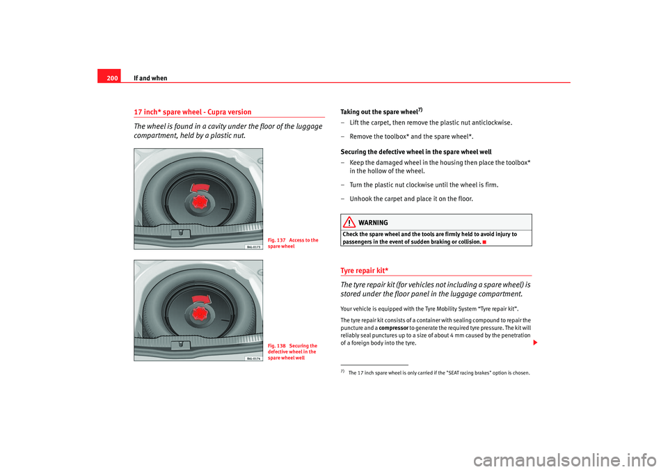
The wheel is found in a cavity under the floor of the luggage
compartment, held by a plastic nut.
Taking out the spare wheel
7)
– Lift the carpet, then remove the plastic nut anticlockwise.
– Remove the toolbox* and the spare wheel*.
Securing the defective wheel in the spare wheel well
– Keep the damaged wheel in the housing then place the toolbox*
in the hollow of the wheel.
– Turn the plastic nut clockwise until the wheel is firm.
– Unhook the carpet and place it on the floor.
WARNING
Check the spare wheel and the tools are firmly held to avoid injury to
passengers in the event of sudden braking or collision.Tyre repair ki t*
The tyre repair kit (for vehicles not including a spare wheel) is
stored under the floor panel in the luggage compartment.Your vehicle is equipped with the Tyre Mobility System “Tyre repair kit”.
The tyre repair kit consists of a container with sealing compound to repair the
puncture and a compressor to generate the required tyre pressure. The kit will
reliably seal punctures up to a size of about 4 mm caused by the penetration
of a foreign body into the tyre.
Fig. 137 Access to the
spare wheelFig. 138 Securing the
defective wheel in the
spare wheel well
7)The 17 inch spare wheel is only carried if the "SEAT racing brakes" option is chosen.
ibiza_angles_0706_DEF Seite 200 Freitag, 1. September 2006 1:18 13
Page 203 of 268

If and when201
Safety First
Operating instructions
Tips and Maintenance
Te c h n i c a l D a t a
Note
•
Seek professional assistance if the repair of a tyre puncture is not
possible with the sealing compound.
Wheel changePreparation work
What you must do before changing a wheel.– If you have a flat tyre or puncture, park the vehicle as far away from the flow of traffic as possible. Choose a location that is as
level as possible.
– All passengers should leave the vehicle. They should wait in a safe area (for instance behind the roadside crash barrier).
– Switch off the engine. Switch on the hazard warning lights.
–Apply the handbrake firmly.
–Engage the first gear, or put the selector lever to position P for
those vehicles with an automatic gearbox.
– If you are towing a trailer, unhitch it from your vehicle.
–Take the vehicle tools and the spare wheel out of the luggage
compartment.
WARNING
Put the hazard warning lights on and place the warning triangle in position.
This is for your own safety and also warns other road users.
Caution
If you have to change the tyre on a gradient, block the wheel opposite the
wheel being changed by placing a stone or similar object under it to prevent
the vehicle from rolling away.
Note
Please observe legal requirements when doing so.Changing a wheelChange the wheel as described below
–Pull off the hub cap see also ⇒page 202.
–Slacken the wheel bolts.
– Raise the car with the jack in the corresponding zone.
– Ta k e o f f the wheel and then put on the spare wheel.
– Lower the vehicle.
– Tighten the wheel bolts firmly i n d i a go na l s e q u e n ce wi t h t h e b ox
spanner.
–Replace the hub cap.
ibiza_angles_0706_DEF Seite 201 Freitag, 1. September 2006 1:18 13
Page 209 of 268

If and when207
Safety First
Operating instructions
Tips and Maintenance
Te c h n i c a l D a t a
There is also a guide to using the compressor.
WARNING
•
The sealant should not be used if th
e tyre has been damaged as a result
of going flat.
•
Follow the instructions for your safety and use on the compressor and
the sealant packaging.
•
Do not drive at more than 80 km/h, avoid accelerating or braking hard
or taking curves at high speed.
•
A tyre that has been repaired with sealant should only be used provi-
sionally, and for a short time. Therefore, your car should be taken carefully
to the nearest specialised workshop.For the sake of the environment
If you want to dispose of the sealant bottle, go to a company that treats waste
products.
Note
Seek professional assistance if the repair of a tyre puncture is not possible
with the sealing compound.Preparation work
What you must do before changing a wheel.– If you have a flat tyre or puncture, park the vehicle as far away from the flow of traffic as possible.
–Apply the handbrake firmly. – Engage the first gear
, or put the selector lever to position P for
those vehicles with an automatic gearbox.
– All passengers must leave the vehicle. They should wait in a safe
area (for instance behind the roadside crash barrier).
– Check whether the puncture can be mended using the Tyre Mobility System “General observations and safety advice.”
– Unscrew cap from the valve of the affected wheel.
– Take the tyre repair kit from the luggage compartment.
WARNING
Put the hazard warning lights on and place the warning triangle in position.
This is for your own safety and also warns other road users.
Caution
Take the utmost caution when repairing a flat tyre on a gradient.
Note
Please observe legal requirements when doing so.
ibiza_angles_0706_DEF Seite 207 Freitag, 1. September 2006 1:18 13
Page 212 of 268
If and when
210Fuses on left side of dash panelFuses
Number Electrical equipment Amperes
1 Secondary water pump 1.8 20 VT (T16) 15
2A BS/E S P 10
3 Vacant
4 Brake light, clutch switch, relay coils 5
5 Engine control unit (petrol) 5
6R ig h t s id e lig h t 5
7L eft s id e lig ht 5
8 Mirror heating unit 5
9 Lambda probe 10
10 Signal “S”
a). Radio unit 5
11 Electric mirror power supply 5
12 Headlamp height adjustment 5
13 Oil pressure/level sensor 5
14 Additional heati ng engine/fuel pump 10
15 Automatic gearbox unit 10
16 Heated seats 15
17 Engine control unit 5
18 Instrument panel /Heating and vent ilation, Navigation, Headlamp height adjustment, Electric mirror 10
19 Reverse light 10
20 Windscreen washer pump 10
21 Main beam headlight, right 10
ibiza_angles_0706_DEF Seite 210 Freitag, 1. September 2006 1:18 13
Page 213 of 268
If and when211
Safety First
Operating instructions
Tips and Maintenance
Te c h n i c a l D a t a
22
Main beam headlight, left 10
23 Number plate light/si de light indicator 5
24 Rear windscreen wiper 10
25 Injectors(fuel) 10
26 Brake light switch /ESP (Turn sensor) 10
27 Instrument panel/Diagnosis 5
28 Unit: glove box light, boot light, interior light 10
29 Climatronic 5
30 Power supply central locking unit 5
31 Left front window control 25
32 Vacant
33 Self powered alarm horn 15
34 Engine control unit 15
35 Sunroof 20
36 Engine ventilator heating /blower 25
37 Headlight washer pump 20
38 Front and rear fog lights 15
39 Engine control unit (petrol) 15
40 Engine control unit diesel + SDI Fuel pump 30
41 Fuel gauge 15
42 Ignition transformer+ E ngine control unit T70 15
43 Dipped headlight (right side) 15
44 Left rear window control 25
45 Front right window control 25
Number
Electrical equipment Amperes
ibiza_angles_0706_DEF Seite 211 Freitag, 1. September 2006 1:18 13
Page 216 of 268

If and when
214Some of the electrical items listed in the table are only fitted on certain
models or are optional extras.
Please note that the above list, while corr ect at the time of printing, is subject
to alterations.Bulb changeGeneral notesBefore changing any bulb first turn off the equipment concerned.
Do not touch the bulb glass. Fingerprints vaporise in the heat, causing a
reduction in the bulb life and conden sation on the mirror surface, thus
reducing efficiency.
A bulb should only be replaced by one of the same type. The type is inscribed
on the bulb, either on the glass part or on the base.
It is highly recommended to keep a box of spare bulbs in the vehicle. At the
very least, the bulbs that most affect road safety should have spares in the
vehicle. Rear lights on frame
Brake/position 12V/P21/5W
Turn signals 12V/P21W
Rear lights on tailgate
Small position light 12V/W5W
Antifog lamp 12V/P21W
Reverse lamp 12V/P21W
Single reflector headlamps*
Full beam/dipped beam 12V 60/55W (H4)
Turn indicator 12V/PY 21W
Position lamp 12/W5W
Double reflector headlamps
Dipped beam 12V/55W (H7)
Full beam 12V/55W (H3)
Turn signals 12V/PY21W
Position lights 12V/W5W
10
Cable control unit 5
11 Clima fan 5
12 Vacant
13 Jatco unit for automatic gearbox 5
14 Vacant
15 Vacant
16 Vacant
Number
Electrical equipment Amperes
ibiza_angles_0706_DEF Seite 214 Freitag, 1. September 2006 1:18 13
Page 225 of 268

If and when223
Safety First
Operating instructions
Tips and Maintenance
Te c h n i c a l D a t a
Rear lights on frameSide light 2/ Brake light/ Indicator light
– Open the tailgate. – Unscrew the screws
⇒fig. 165 using a flat-blade screwdriver.
– Move the rear light outwards and pull.
– If necessary, unplug the connector.
– Unscrew the bolt ⇒fig. 166 .
– Take out the lamp holder.
– Press and rotate the lamps to the left.
– Remove faulty lamp and replace it.
– Proceed in the reverse order, pressing gently on the outer edge of the rear light (in the area of the metal clips).
Note
Make sure that when assembling all seals and rubbers are correctly fitted.Number plate light– Release transparent lamp cover by levering the tab with the flat part of a screwdriver.
– Remove the defective lamp from the lamp holder, holding it in the centre, press to one side and fit new lamp.
– Fit lamp cover in its space, taking special care when replacing the rubber seal and press until it clicks into place.
Fig. 165 Rear lights on
bodyworkFig. 166 Rear lights on
bodywork
AF
AG
ibiza_angles_0706_DEF Seite 223 Freitag, 1. September 2006 1:18 13
Page 226 of 268

If and when
224Interior light and front reading light To r e m o v e g l a s s
– Insert a fine screwdriver between the casing and the glass
⇒fig. 167.
– Carefully remove the glass, levering it to avoid possible damage.
To replace the lamps
– Pull the lamps outwards.
– To remove the central lamp, hold and press to one side.
Assembly
– Proceed in the reverse order, pressing gently on the outer edge of the side light. – First fit the glass with the fastening tabs over the frame of the
switch. Next press the front part until the two long tabs click on
the support.
Additional brake lights*Given the difficulty involved in the replacement of this light it should be done
by the Technical Service.Glove box light*– Insert screwdriver above, between the light and the glove box.
– Carefully remove the light Next lift the light out sideways.
– Replace the bulb.
– Insert the light on the connector side, first underneath then push at the top until it clicks into place.
Fig. 167 Front reading
light
ibiza_angles_0706_DEF Seite 224 Freitag, 1. September 2006 1:18 13