2006 Seat Altea change wheel
[x] Cancel search: change wheelPage 92 of 288

Steering wheel controls
90
Cyclic change of source
Radio - CD / CDC - Radio - ...
When in Navigation mode the system leaves the navigation screen. Repeat the last Navigation instruction
Only if the Navigation function is activated.
Voice recognition activation Press to speak No specified function
Make a call or
Direct access to the phone book or
Accept a call No specified function
Terminate call or
Refuse call or
Quite telephone menu No specified function
a)Only for those Radio-Navigation Systems compatible with the MP3 formatAEAFAGAH
altea_ingles Seite 90 Dienstag, 4. Oktober 2005 6:57 18
Page 117 of 288

Lights and visibility115
Safety First
Operating instructions
Tips and Maintenance
Te c h n i c a l D a t a
•
Never park where the catalytic converter could come into contact with
inflammable materials under the vehicle, for example dry grass or spilt
petrol. This could start a fire!Note
•
The battery will run down if the hazard warning lights are left on for a long
time, even if the ignition is switched off.
•
The use of the hazard warning lights d escribed here is subject to the rele-
vant statutory requirements.
Turn signal and main beam headlight lever
The turn signal and main beam lever also operates the
parking lights and the headlight flasher.
The turn signal and main beam headlight lever has the following
functions:
Switching on the turn signals
– Move the lever all the way up ⇒fig. 78 to indicate right, and
all the way down to indicate left.
Signalling a lane change
– Push the lever up or down to the point where you incur resistance and then release the lever. The turn signal will flash
three times. The corresponding warning lamp will also flash.
Switching main beam on and off
– Turn the light switch to position
.
– Press the lever forward ⇒fig. 78 to switch on the main
beams.
– Pull the lever back towards you to switch the main beam head- lights off again.
Headlight flasher
– Pull the lever towards the steering wheel to operate the flasher.
Switching on parking lights
– Switch off the ignition and remove the key from the lock.
– Move the lever up or down to turn on the right or left-hand parking lights respectively.
WARNING (continued)
Fig. 78 Turn signal and
main beam headlight
lever
A1
A2A1
A2A3
A4
altea_ingles Seite 115 Dienstag, 4. Oktober 2005 6:57 18
Page 179 of 288

Intelligent technology177
Safety First
Operating instructions
Tips and Maintenance
Te c h n i c a l D a t a
The TCS should be switched on again afterwards as soon as possible.
WARNING
•
It must be remembered that TCS cann
ot defy the laws of physics. This
should be kept in mind, particular ly on slippery and wet roads and when
towing a trailer.
•
Always adapt your driving style to suit the condition of the roads and
the traffic situation. Do not let the extra safety afforded by TCS tempt you
into taking any risks when driving, this can cause accidents.Caution
•
In order to ensure that TCS function correctly, all four wheels must be
fitted with the same tyres. Any differences in the rolling radius of the tyres can
cause the system to reduce engine power when this is not desired.
•
Modifications to the vehicle (e.g. to the engine, the brake system, running
gear or any components affecting the wh eels and tyres) could affect the effi-
ciency of the ABS and TCS.
Electronic stabilisation program (ESP)*General notes
The electronic stabilisation program increases the vehicles
stability on the road.The electronic stabilisation program helps to reduce the danger of skidding.
The electronic stabilisation programme (ESP) consists of ABS, EDL, TCS and
Steering manoeuvre recommendations. Electronic Stabilising Program (ESP)*
ESP reduces the danger of skidding by braking the wheels individually.
The system uses the steering wheel angle and road speed to calculate the
changes of direction desired by the driver, and constantly compares them
with the actual behaviour of the vehi
cle. If the desired course is not being
maintained (for instance, if the car is starting to skid), then the ESP compen-
sates automatically by braking the appropriate wheel.
The forces acting on the braked wheel bring the vehicle back to a stable
condition. If the vehicle tends to oversteer, the system will act on the front
wheel on the outside of the turn.
Steering manoeuvre recommendations
This is a complementary safety function included in the ESP This function aids
the driver to better stabilize the vehicle in a critical situation. For example, in
case of sudden braking surface with varied adherence, the vehicle will tend
to destabilize its trajectory to the right to or to the left. In this case the ESP
recognizes the situation and helps the driver with a counter steering
manoeuvre from the power steering.
This function simply provides the dr iver with a recommended manoeuvre in
critical situations.
The vehicle doesn't steer itself with this function, the driver has full control of
the vehicle at all times.
WARNING
•
It must be remembered that ESP cann ot defy the laws of physics. This
should be kept in mind, particularly on slippery and wet roads and when
towing a trailer.
•
Always adapt your driving style to suit the condition of the roads and
the traffic situation. Do not let the extra safety afforded by ESP tempt you
into taking any risks when driving, this can cause accidents.
altea_ingles Seite 177 Dienstag, 4. Oktober 2005 6:57 18
Page 224 of 288

Checking and refilling levels
222Wear indicators
The original tyres on your vehicle have 1.6 mm high “tread wear
indi cators ” ⇒ p
age 221, fig. 162 running acro ss the tread. Depending on the
make, there will be six to eight of them evenly spaced around the tyre. Mark-
ings o n the tyre sidewall (fo r instance the letters “TWI” or other symbols) indi-
cate the positions of the tread wear indicators. The minimum tread depth
required by law is 1.6 mm (measured in the tread grooves next to the tread
wear indicators). Worn tyres must be replaced. Different figures may apply in
export countries ⇒.
Tyre pressure
Incorrect tyre pressure causes premature wear and could cause tyre blow-out.
For this reason, the tyre pressure should be checked at least once per month
⇒ page 221.
Driving style
Fast cornering, heavy acceleration and hard braking all increase tyre wear.
Changing wheels around
If the front tyres are worn considerably more than the rear ones it is advisable
to change them around as shown ⇒page 221, fig. 163. All the tyres will then
last for about the same time.
Wheel balance
The wheels on new vehicles are balanced. However, various factors encoun-
tered in normal driving can cause them to become unbalanced, which results
in steering vibration.
Unbalanced wheels should be rebalanced, as they otherwise cause excessive
wear on steering, suspension and tyre s. A wheel must also be rebalanced
when a new tyre is fitted.
Incorrect wheel alignment
Incorrect wheel alignment causes excessiv e tyre wear, impairing the safety of
the vehicle. If tyres show excessive wear, you should have the wheel align-
ment checked by an Authorised Service Centre.
WARNING
There is a serious danger of accidents if a tyre bursts during driving!•
The tyres must be replaced at the latest when the tread is worn down to
the tread wear indicators. Failure to do so could result in an accident. Worn
tyres do not grip well at high speeds on wet roads. There is also a greater
risk of “aquaplaning”.
•
At continuously high speeds, a tyre with insufficient pressure flexes
more. This causes it to overheat. This can cause tread separation and tyre
blow-out. Risk of accident. Always observe the recommended tyre pres-
sures.
•
If tyres show excessive wear, you should have the running gear checked
by an Authorised Service Centre.
•
Keep chemicals such as oil, fuel and brake fluid away from tyres.
•
Damaged wheels and tyres must be replaced immediately!For the sake of the environment
Under-inflated tyres will increase fuel consumption.New tyres and wheels
New tyres and wheels have to be run-in.The tyres and wheel rims are an essen tial part of the vehicles design. The
tyres and rims approved by SEAT are specially matched to the characteristics
of the vehicle and make a major contribution to good road holding and safe
handling ⇒.
Tyres should be replaced at least in pairs and not individually (i.e. both front
tyres or both rear tyres together). A knowledge of tyre designations makes it
altea_ingles Seite 222 Dienstag, 4. Oktober 2005 6:57 18
Page 229 of 288

If and when227
Safety First
Operating instructions
Tips and Maintenance
Te c h n i c a l D a t a
Compact temporary spare wheel
The compact temporary spare wh eel is only intended for
temporary use over short distances.The temporary spare wheel is stored under the floor panel in the luggage
compartment and is attached by a thumbnut.
How to use the compact temporary spare wheel
Should you ever have a punctured tyre, the compact temporary spare wheel
is only intended for temporary use until you can reach a workshop. The
standard-size road wheel should be replaced as soon as possible.
Please note the following restrictions when using the compact temporary
spare wheel. This spare wheel has been specially designed for your vehicle,
thus, it cannot be changed with th e spare wheel from another vehicle.
No other type of tyre (normal summer or winter tyre) may be fitted on the
compact temporary spare wheel rim. Snow chains
For technical reasons, snow chains must not
be used on the compact tempo-
rary spare wheel.
If you should have a puncture on one of the front wheels when using snow
chains, fit the compact temporary spare in place of one of the rear wheels.
You can then attach the snow chains to the wheel taken from the rear and use
this wheel to replace the punctured front wheel.
WARNING
•
The tyre pressures must be checked and corrected as soon as possible.
The tyre pressure for the spare wheel is 4.2 bar. Failure to do so could result
in an accident.
•
Do not drive faster than 80 km/h. High er speeds can cause an accident.
•
Avoid heavy acceleration, hard braking and fast cornering, risk of acci-
dent.
•
Never use two or more compact spare tyres at the same time, risk of
accident.
•
No other type of tyre (normal summer or winter tyre) may be fitted on
the compact temporary spare wheel rim.
Tyre repair kit
The tyre repair kit is stored under the floor panel in the
luggage compartmentYour vehicle is equipped with the Tyre Mobility System “Tyre repair kit”.
The tyre repair kit consists of a contai ner with sealing compound to repair the
puncture and a compressor to generate the required tyre pressure. The kit will
reliably seal punctures up to a size of about 4 mm caused by the penetration
of a foreign body into the tyre.
Fig. 164 Luggage
compartment. Access to
the spare wheel
altea_ingles Seite 227 Dienstag, 4. Oktober 2005 6:57 18
Page 230 of 288

If and when
228
Note•
Seek professional assistance if the repair of a tyre puncture is not
possible with the sealing compound.
Wheel changePreparation work
What you must do before changing a wheel.– If you have a flat tyre or puncture, park the vehicle as far away from the flow of traffic as possible. Choose a location that is as
level as possible.
– All passengers should leave the ve hicle. They should wait in a
safe area (for instance behind the roadside crash barrier).
– Switch off the engine. Switch on the hazard warning lights.
–Apply the handbrake firmly.
– Engage the first gear, or put the selector lever to position P for
those vehicles with an automatic gearbox.
– If you are towing a trailer, unhitch it from your vehicle.
– Take the vehicle tools and the spare wheel out of the luggage
compartment.
WARNING
Put the hazard warning lights on and place the warning triangle in position.
This is for your own safety and also warns other road users.
Caution
If you have to change the tyre on a gradient, block the wheel opposite the
wheel being changed by placing a stone or similar object under it to prevent
the vehicle from rolling away.
Note
Please observe legal requirements when doing so.Changing a wheelChange the wheel as described below
– Remo ve the wheel co ve r. A lso r e
fer to ⇒ pag
e 229, fig. 165
.
– Slac
ken the wheel bolts .
– Raise the car with the jack in the corresponding zone
– Ta k e o f f the wheel and then put on the spare wheel
– Lower the vehicle.
– Tighten the wheel bolts firmly in diagonal sequence with the box
spanner
–Replace the cover .
altea_ingles Seite 228 Dienstag, 4. Oktober 2005 6:57 18
Page 233 of 288

If and when231
Safety First
Operating instructions
Tips and Maintenance
Te c h n i c a l D a t a
WARNING
Loosen the wheel bolts only about one tu rn before raising the vehicle with
the jack, loosening the wheel bolts more than one turn can result in an acci-
dent.
Note
•
Do not use the hexagonal socket in th e screwdriver handle to loosen or
tighten the wheel bolts.
•
If the wheel bolt is very tight, you may be able to loosen it by pushing
down the end of the spanner carefully with your foot. Hold on to the vehicle
for support and take care not to slip.
Raising the vehicle
The vehicle must be raised with a jack to remove the wheel.
– Locate the jacking point under the door sill closest to the wheel being changed ⇒ fig. 167.
–
Wind up the jack under the jacking point until the arm of the jack
is directly below the vertical rib under the door sill.
– Align the jack so that the arm of the jack fits around the rib under the door sill and the movable base plate of the jack is flat on the
ground ⇒ fig. 168 .
– R
aise the vehicle until the defect ive wheel is just clear of the
ground.
Recesses at the front and rear of the door sills mark the jacking points
⇒ fig. 167 . A position has been made for each wheel. Do not fit the jack
anywhere else.
An unstable surface under the jack may cause the vehicle to slip off the jack.
Therefore, the jack must be fitted on solid ground offering good support. Use
Fig. 167 The jacking
points
Fig. 168 Fitting the jack
altea_ingles Seite 231 Dienstag, 4. Oktober 2005 6:57 18
Page 234 of 288
If and when
232a large and stable base, if necessary. On a hard, slippery surface (such as
tiles) use a rubber mat or similar to prevent the jack from slipping.
WARNING
•
Take all precautions so that the base of the jack does not slip. Failure to
do so could result in an accident.
•
The vehicle can be damaged if the jack is not applied at the correct
jacking points. There is also a risk of injury since the jack can slip off
suddenly if it is not properly engaged.
Removing and fitting the wheel
For removal and fitting the wheel, the following tasks must be
completed.Change the wheel as described below after loosening the wheel
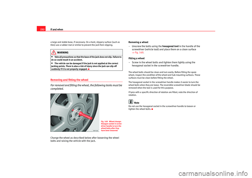
bolts and raising the vehicle with the jack. Removing a wheel
– Unscrew the bolts using the
hexagonal tool in the handle of the
screwdriver (vehicle tool) and place them on a clean surface
⇒ fig. 169.
Fitting a wheel
– Screw in the wheel bolts and tighten them lightly using the hexagonal socket in the screwdriver handle.
The wheel bolts should be clean and turn easily. Before fitting the spare
wheel, inspect the condition of the whe el and hub mounting surfaces. These
surfaces must be clean before fitting the wheel.
The hexagonal socket in the screwdriver handle makes it easier to turn the
wheel bolts when they are loose. The reversible screwdrive r blade should be
removed when the tool is used for this purpose.
If tyres with a specific di rection of rotation are fitt ed, note the direction of
rotation.
Note
Do not use the hexagonal socket in the screwdriver handle to loosen or
tighten the wheel bolts.
Fig. 169 Wheel change:
Hexagon socket in screw-
driver handle to turn the
wheel bolts after they
have been loosened
altea_ingles Seite 232 Dienstag, 4. Oktober 2005 6:57 18