Page 1722 of 2896
ASCD BRAKE SWITCH
EC-553
C
D
E
F
G
H
I
J
K
L
MA
EC
Revision: June 20062007 Versa
2. CHECK OVERALL FUNCTION-II
With CONSULT-II
Check “BRAKE SW2” indication in “DATA MONITOR” mode.
Without CONSULT-II
Check voltage between ECM terminal 99 and ground under the fol-
lowing conditions.
OK or NG
OK >> GO TO 15.
NG >> GO TO 11.
3. CHECK ASCD CLUTCH SWITCH POWER SUPPLY CIRCUIT
1. Turn ignition switch OFF.
2. Disconnect ASCD clutch switch (1) harness connector.
–Clutch pedal (2)
3. Turn ignition switch ON.
4. Check voltage between ASCD clutch switch terminal 1 and
ground with CONSULT-II or tester.
OK or NG
OK >> GO TO 9.
NG >> GO TO 4.
CONDITION INDICATION
Brake pedal: Fully released OFF
Brake pedal: Slightly depressed ON
SEC0 13 D
CONDITION VOLTAGE
Brake pedal: Fully released Approximately 0V
Brake pedal: Slightly depressed Battery voltage
PBIB0 311 E
BBIA0709E
Voltage: Battery voltage
PBIB0857E
Page 1723 of 2896

EC-554Revision: June 2006
ASCD BRAKE SWITCH
2007 Versa
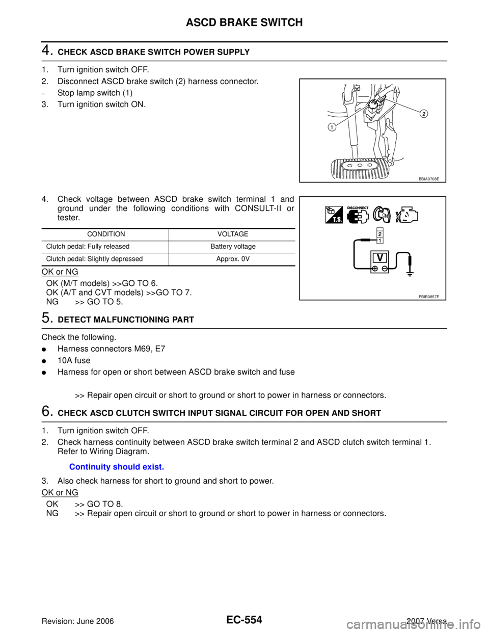
4. CHECK ASCD BRAKE SWITCH POWER SUPPLY
1. Turn ignition switch OFF.
2. Disconnect ASCD brake switch (2) harness connector.
–Stop lamp switch (1)
3. Turn ignition switch ON.
4. Check voltage between ASCD brake switch terminal 1 and
ground under the following conditions with CONSULT-II or
tester.
OK or NG
OK (M/T models) >>GO TO 6.
OK (A/T and CVT models) >>GO TO 7.
NG >> GO TO 5.
5. DETECT MALFUNCTIONING PART
Check the following.
�Harness connectors M69, E7
�10A fuse
�Harness for open or short between ASCD brake switch and fuse
>> Repair open circuit or short to ground or short to power in harness or connectors.
6. CHECK ASCD CLUTCH SWITCH INPUT SIGNAL CIRCUIT FOR OPEN AND SHORT
1. Turn ignition switch OFF.
2. Check harness continuity between ASCD brake switch terminal 2 and ASCD clutch switch terminal 1.
Refer to Wiring Diagram.
3. Also check harness for short to ground and short to power.
OK or NG
OK >> GO TO 8.
NG >> Repair open circuit or short to ground or short to power in harness or connectors.
BBIA0708E
CONDITION VOLTAGE
Clutch pedal: Fully released Battery voltage
Clutch pedal: Slightly depressed Approx. 0V
PBIB0857E
Continuity should exist.
Page 1726 of 2896

ASCD BRAKE SWITCH
EC-557
C
D
E
F
G
H
I
J
K
L
MA
EC
Revision: June 20062007 Versa
14. CHECK STOP LAMP SWITCH
Refer to EC-481, "
Component Inspection"
OK or NG
OK >> GO TO 15.
NG >> Replace stop lamp switch.
15. CHECK INTERMITTENT INCIDENT
Refer to EC-143, "
TROUBLE DIAGNOSIS FOR INTERMITTENT INCIDENT" .
>>INSPECTION END
Component InspectionUBS00QO0
ASCD BRAKE SWITCH
1. Turn ignition switch OFF.
2. Disconnect ASCD brake switch harness connector.
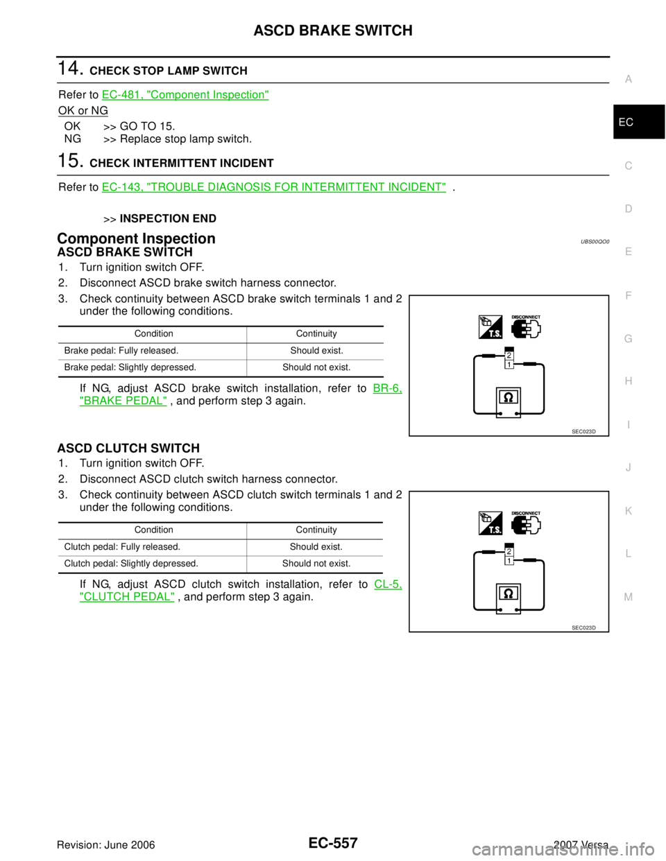
3. Check continuity between ASCD brake switch terminals 1 and 2
under the following conditions.
If NG, adjust ASCD brake switch installation, refer to BR-6,
"BRAKE PEDAL" , and perform step 3 again.
ASCD CLUTCH SWITCH
1. Turn ignition switch OFF.
2. Disconnect ASCD clutch switch harness connector.
3. Check continuity between ASCD clutch switch terminals 1 and 2
under the following conditions.
If NG, adjust ASCD clutch switch installation, refer to CL-5,
"CLUTCH PEDAL" , and perform step 3 again.
Condition Continuity
Brake pedal: Fully released. Should exist.
Brake pedal: Slightly depressed. Should not exist.
SEC0 23 D
Condition Continuity
Clutch pedal: Fully released. Should exist.
Clutch pedal: Slightly depressed. Should not exist.
SEC0 23 D
Page 1727 of 2896
EC-558Revision: June 2006
ASCD BRAKE SWITCH
2007 Versa
STOP LAMP SWITCH
1. Turn ignition switch OFF.
2. Disconnect stop lamp switch harness connector.
3. Check continuity between stop lamp switch terminals 1 and 2 under the following conditions.
If NG, adjust stop lamp switch installation, refer to BR-6, "
BRAKE PEDAL" , and perform step 3 again.
Condition Continuity
Brake pedal: Fully released. Should not exist.
Brake pedal: Slightly depressed. Should exist.
PBIB3318E
Page 1937 of 2896

FAX-6
FRONT WHEEL HUB AND KNUCKLE
Revision: June 20062007 Versa
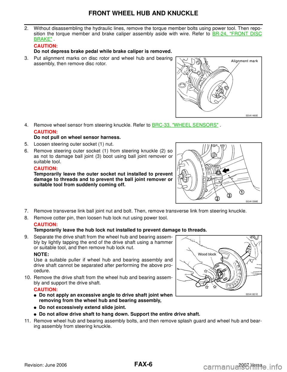
2. Without disassembling the hydraulic lines, remove the torque member bolts using power tool. Then repo-
sition the torque member and brake caliper assembly aside with wire. Refer to BR-24, "
FRONT DISC
BRAKE" .
CAUTION:
Do not depress brake pedal while brake caliper is removed.
3. Put alignment marks on disc rotor and wheel hub and bearing
assembly, then remove disc rotor.
4. Remove wheel sensor from steering knuckle. Refer to BRC-33, "
WHEEL SENSORS" .
CAUTION:
Do not pull on wheel sensor harness.
5. Loosen steering outer socket (1) nut.
6. Remove steering outer socket (1) from steering knuckle (2) so
as not to damage ball joint (3) boot using ball joint remover or
suitable tool.
CAUTION:
Temporarily leave the outer socket nut installed to prevent
damage to threads and to prevent the ball joint remover or
suitable tool from suddenly coming off.
7. Remove transverse link ball joint nut and bolt. Then, remove transverse link from steering knuckle.
8. Remove cotter pin, then loosen hub lock nut using power tool.
CAUTION:
Temporarily leave the hub lock nut installed to prevent damage to threads.
9. Separate the drive shaft from the wheel hub and bearing assem-
bly by lightly tapping the end of the drive shaft using a hammer
or suitable tool, and then remove hub lock nut.
NOTE:
Use a suitable puller if wheel hub and bearing assembly and
drive shaft cannot be separated after performing the above pro-
cedure.
10. Remove the drive shaft from the wheel hub and bearing assem-
bly and support the drive shaft.
CAUTION:
�Do not apply an excessive angle to drive shaft joint when
removing from the wheel hub and bearing assembly,
�Do not excessively extend slide joint.
�Do not allow drive shaft to hang down. Support the entire drive shaft.
11. Remove wheel hub and bearing assembly bolts, and then remove splash guard and wheel hub and bear-
ing assembly from steering knuckle.
SDIA1480E
SGIA1298E
SDIA1821E
Page 2175 of 2896
![NISSAN VERSA 2006 Workshop Service Repair Manual TROUBLE DIAGNOSIS
LAN-49
[CAN]
C
D
E
F
G
H
I
J
L
MA
B
LAN
Revision: June 20062007 Versa
*1: Models with Intelligent Key system
*2: Models with ABS
*3: Models with air conditioner
*4: Models for Canada NISSAN VERSA 2006 Workshop Service Repair Manual TROUBLE DIAGNOSIS
LAN-49
[CAN]
C
D
E
F
G
H
I
J
L
MA
B
LAN
Revision: June 20062007 Versa
*1: Models with Intelligent Key system
*2: Models with ABS
*3: Models with air conditioner
*4: Models for Canada](/manual-img/5/57401/w960_57401-2174.png)
TROUBLE DIAGNOSIS
LAN-49
[CAN]
C
D
E
F
G
H
I
J
L
MA
B
LAN
Revision: June 20062007 Versa
*1: Models with Intelligent Key system
*2: Models with ABS
*3: Models with air conditioner
*4: Models for Canada
*5: Models for USA
NOTE:
CAN data of the air bag diagnosis sensor unit is not used by usual service work, thus it is omitted.
TYPE 5/TYPE 6
NOTE:
Refer to LAN-41, "
Abbreviation List" for the abbreviations of the connecting units.
T: Transmit R: Receive Sleep/wake up signalRT
TRRR
Vehicle speed signalRRR T
RRRT
ABS warning lamp signalRT
Brake warning lamp signalRT
Front wiper stop position signal R T
High beam status signal RT
Low beam status signal RT
Oil pressure switch signalRT
Rear window defogger control signal RT Signals ECM BCM EPS
I-KEY
*1M&A
ABS*2IPDM-E
Signals ECM BCM EPS M&A
ABS*1TCM IPDM-E
A/C compressor request signal
*2TR
Accelerator pedal position signal T R
ASCD CRUISE lamp signal T R
ASCD SET lamp signal T R
Closed throttle position signal T R
Cooling fan motor operation signal TR
Engine coolant temperature signal T R
Engine speed signal T R
Engine status signal T R
Fuel consumption monitor signal T R
Malfunction indicator lamp signal T R
Wide open throttle position signal T R
A/C switch signal
*2RT
Blower fan motor switch signal R T
Buzzer output signalTR
R
Day time running light request signal
*3TR
Door switch signal T R R
Front wiper request signal T R
High beam request signal T R R
Horn chirp signal T R
Ignition switch signal T R
Page 2176 of 2896
![NISSAN VERSA 2006 Workshop Service Repair Manual LAN-50
[CAN]
TROUBLE DIAGNOSIS
Revision: June 20062007 Versa
*1: Models with ABS
*2: Models with air conditioner
*3: Models for Canada
*4: Models for USA
NOTE:
CAN data of the air bag diagnosis sensor NISSAN VERSA 2006 Workshop Service Repair Manual LAN-50
[CAN]
TROUBLE DIAGNOSIS
Revision: June 20062007 Versa
*1: Models with ABS
*2: Models with air conditioner
*3: Models for Canada
*4: Models for USA
NOTE:
CAN data of the air bag diagnosis sensor](/manual-img/5/57401/w960_57401-2175.png)
LAN-50
[CAN]
TROUBLE DIAGNOSIS
Revision: June 20062007 Versa
*1: Models with ABS
*2: Models with air conditioner
*3: Models for Canada
*4: Models for USA
NOTE:
CAN data of the air bag diagnosis sensor unit is not used by usual service work, thus it is omitted.
TYPE 7/TYPE 8/TYPE 9/TYPE 10
NOTE:
Refer to LAN-41, "
Abbreviation List" for the abbreviations of the connecting units.
T: Transmit R: Receive Low beam request signal T R
Position lights request signal T R R
Rear window defogger switch signal T R
Theft warning horn request signal T R
Tire pressure signal
*4TR
Turn indicator signal T R
EPS operation signal R T
EPS warning lamp signal T R
Fuel level sensor signal R T
Overdrive control switch signal T R
P/N range signal T R
Sleep/wake up signalRT
TR R
Stop lamp switch signal T R
Vehicle speed signalRRR T
RRRT
ABS warning lamp signal R T
Brake warning lamp signal R T
A/T check indicator signal R T
A/T self-diagnosis signal R T
OD OFF indicator signal R T
Output shaft revolution signal R T
Shift position signal R T
Turbine revolution signal R T
Front wiper stop position signal R T
High beam status signal RT
Low beam status signal RT
Oil pressure switch signal R T
Rear window defogger control signal RT Signals ECM BCM EPS M&A
ABS
*1TCM IPDM-E
Signals ECM BCM EPS
I-KEY*1M&A
ABS*2TCM IPDM-E
A/C compressor request signal TR
Accelerator pedal position signal T R
ASCD CRUISE lamp signal T R
ASCD SET lamp signal T R
Closed throttle position signal T R
Page 2177 of 2896
![NISSAN VERSA 2006 Workshop Service Repair Manual TROUBLE DIAGNOSIS
LAN-51
[CAN]
C
D
E
F
G
H
I
J
L
MA
B
LAN
Revision: June 20062007 Versa
Cooling fan motor operation signal TR
Engine coolant temperature signal T R
Engine speed signal T R R
Engine sta NISSAN VERSA 2006 Workshop Service Repair Manual TROUBLE DIAGNOSIS
LAN-51
[CAN]
C
D
E
F
G
H
I
J
L
MA
B
LAN
Revision: June 20062007 Versa
Cooling fan motor operation signal TR
Engine coolant temperature signal T R
Engine speed signal T R R
Engine sta](/manual-img/5/57401/w960_57401-2176.png)
TROUBLE DIAGNOSIS
LAN-51
[CAN]
C
D
E
F
G
H
I
J
L
MA
B
LAN
Revision: June 20062007 Versa
Cooling fan motor operation signal TR
Engine coolant temperature signal T R
Engine speed signal T R R
Engine status signal T R
Fuel consumption monitor signal T R
Malfunction indicator lamp signal T R
Wide open throttle position signal T R
A/C switch signal R T
Blower fan motor switch signal R T
Buzzer output signalTR
TR
Day time running light request signal
*3TRR
Door lock/unlock status signal T R
Door switch signal T R R R
Front wiper request signal T R
High beam request signal T R R
Horn chirp signal T R
Ignition switch signal T R
Low beam request signal T R
Position lights request signal T R R
Rear window defogger switch signal T R
Theft warning horn request signal T R
Tire pressure signal
*4
Trunk open/close status signal T R
Turn indicator signal T R
EPS operation signal R T
EPS warning lamp signal T R
Door lock/unlock/trunk open request signal R T
Hazard request signal R T
Ignition knob switch signal R T
KEY warning lamp signal T R
LOCK warning lamp signal T R
Panic alarm request signal R T
Fuel level sensor signal R T
Sleep/wake up signalRT
TRR R
Overdrive control switch signal T R
Stop lamp switch signal T R
Vehicle speed signalRRR T
RRRTR
R
*5R*5T*5
ABS warning lamp signal R T
Brake warning lamp signal R T
CVT self-diagnosis signal R TSignals ECM BCM EPS
I-KEY
*1M&A
ABS*2TCM IPDM-E