Page 1161 of 2896

DI-52
WARNING CHIME
Revision: June 20062007 Versa
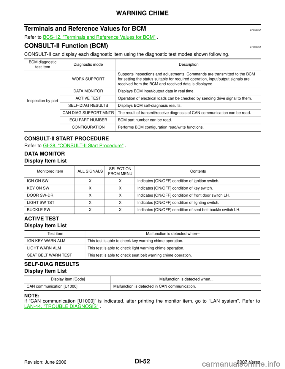
Terminals and Reference Values for BCMEKS00I12
Refer to BCS-12, "Terminals and Reference Values for BCM" .
CONSULT-II Function (BCM)EKS00I13
CONSULT-II can display each diagnostic item using the diagnostic test modes shown following.
CONSULT-II START PROCEDURE
Refer to GI-38, "CONSULT-II Start Procedure" .
DATA MONITOR
Display Item List
ACTIVE TEST
Display Item List
SELF-DIAG RESULTS
Display Item List
NOTE:
If “CAN communication [U1000]” is indicated, after printing the monitor item, go to “LAN system”. Refer to
LAN-44, "
TROUBLE DIAGNOSIS" .
BCM diagnostic
test itemDiagnostic mode Description
Inspection by partWORK SUPPORTSupports inspections and adjustments. Commands are transmitted to the BCM
for setting the status suitable for required operation, input/output signals are
received from the BCM and received data is displayed.
DATA MONITOR Displays BCM input/output data in real time.
ACTIVE TEST Operation of electrical loads can be checked by sending drive signal to them.
SELF-DIAG RESULTS Displays BCM self-diagnosis results.
CAN DIAG SUPPORT MNTR The result of transmit/receive diagnosis of CAN communication can be read.
ECU PART NUMBER BCM part number can be read.
CONFIGURATION Performs BCM configuration read/write functions.
Monitored item ALL SIGNALSSELECTION
FROM MENUContents
IGN ON SW X X Indicates [ON/OFF] condition of ignition switch.
KEY ON SW X X Indicates [ON/OFF] condition of key switch.
DOOR SW-DR X X Indicates [ON/OFF] condition of front door switch LH.
LIGHT SW 1ST X X Indicates [ON/OFF] condition of lighting switch.
BUCKLE SW X X Indicates [ON/OFF] condition of seat belt buckle switch LH.
Test item Malfunction is detected when···
IGN KEY WARN ALM This test is able to check key warning chime operation.
LIGHT WARN ALM This test is able to check light warning chime operation.
SEAT BELT WARN TEST This test is able to check seat belt warning chime operation.
Display item [Code] Malfunction is detected when...
CAN communication [U1000] Malfunction is detected in CAN communication.
Page 2860 of 2896

WW-12
FRONT WIPER AND WASHER SYSTEM
Revision: June 20062007 Versa
Terminals and Reference Values for BCMEKS00I1M
Refer to BCS-12, "Terminals and Reference Values for BCM" .
Terminals and Reference Values for IPDM E/REKS00I1O
Refer to PG-25, "Terminals and Reference Values for IPDM E/R" .
How to Proceed With Trouble DiagnosisEKS00I1P
1. Confirm symptoms and customer complaint.
2. Understand operation description and function description. Refer to WW-4, "
System Description" .
3. Perform preliminary check. Refer to WW-12, "
Preliminary Check" .
4. Check symptom and repair or replace malfunctioning parts.
5. Does front wiper and washer operate normally? If YES, GO TO 6. If NO, GO TO 4.
6. INSPECTION END
Preliminary CheckEKS00I1Q
CHECK POWER SUPPLY AND GROUND CIRCUIT FOR BCM
Refer to BCS-16, "BCM Power Supply and Ground Circuit Check"
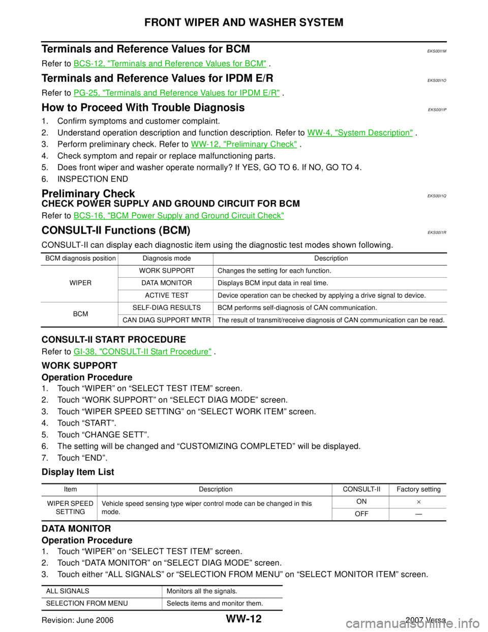
CONSULT-II Functions (BCM)EKS00I1R
CONSULT-II can display each diagnostic item using the diagnostic test modes shown following.
CONSULT-II START PROCEDURE
Refer to GI-38, "CONSULT-II Start Procedure" .
WORK SUPPORT
Operation Procedure
1. Touch “WIPER” on “SELECT TEST ITEM” screen.
2. Touch “WORK SUPPORT” on “SELECT DIAG MODE” screen.
3. Touch “WIPER SPEED SETTING” on “SELECT WORK ITEM” screen.
4. Touch “START”.
5. Touch “CHANGE SETT”.
6. The setting will be changed and “CUSTOMIZING COMPLETED” will be displayed.
7. Touch “END”.
Display Item List
DATA MONITOR
Operation Procedure
1. Touch “WIPER” on “SELECT TEST ITEM” screen.
2. Touch “DATA MONITOR” on “SELECT DIAG MODE” screen.
3. Touch either “ALL SIGNALS” or “SELECTION FROM MENU” on “SELECT MONITOR ITEM” screen.
BCM diagnosis position Diagnosis mode Description
WIPERWORK SUPPORT Changes the setting for each function.
DATA MONITOR Displays BCM input data in real time.
ACTIVE TEST Device operation can be checked by applying a drive signal to device.
BCMSELF-DIAG RESULTS BCM performs self-diagnosis of CAN communication.
CAN DIAG SUPPORT MNTR The result of transmit/receive diagnosis of CAN communication can be read.
Item Description CONSULT-II Factory setting
WIPER SPEED
SETTINGVehicle speed sensing type wiper control mode can be changed in this
mode.ON×
OFF —
ALL SIGNALS Monitors all the signals.
SELECTION FROM MENU Selects items and monitor them.
Page 2862 of 2896

WW-14
FRONT WIPER AND WASHER SYSTEM
Revision: June 20062007 Versa
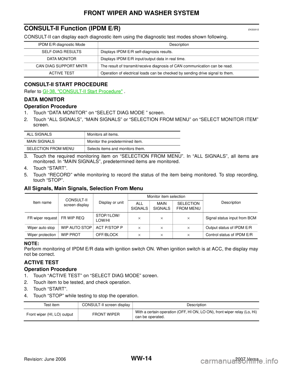
CONSULT-II Function (IPDM E/R)EKS00I1S
CONSULT-II can display each diagnostic item using the diagnostic test modes shown following.
CONSULT-II START PROCEDURE
Refer to GI-38, "CONSULT-II Start Procedure" .
DATA MONITOR
Operation Procedure
1. Touch “DATA MONITOR” on “SELECT DIAG MODE ” screen.
2. Touch “ALL SIGNALS”, “MAIN SIGNALS” or “SELECTION FROM MENU” on “SELECT MONITOR ITEM”
screen.
3. Touch the required monitoring item on “SELECTION FROM MENU”. In “ALL SIGNALS”, all items are
monitored. In “MAIN SIGNALS”, predetermined items are monitored.
4. Touch “START”.
5. Touch “RECORD” while monitoring to record the status of the item being monitored. To stop recording,
touch “STOP”.
All Signals, Main Signals, Selection From Menu
NOTE:
Perform monitoring of IPDM E/R data with ignition switch ON. When ignition switch is at ACC, the display may
not be correct.
ACTIVE TEST
Operation Procedure
1. Touch “ACTIVE TEST” on “SELECT DIAG MODE” screen.
2. Touch item to be tested, and check operation.
3. Touch “START”.
4. Touch “STOP” while testing to stop the operation.
IPDM E/R diagnostic Mode Description
SELF-DIAG RESULTS Displays IPDM E/R self-diagnosis results.
DATA MONITOR Displays IPDM E/R input/output data in real time.
CAN DIAG SUPPORT MNTR The result of transmit/receive diagnosis of CAN communication can be read.
ACTIVE TEST Operation of electrical loads can be checked by sending drive signal to them.
ALL SIGNALS Monitors all items.
MAIN SIGNALS Monitor the predetermined item.
SELECTION FROM MENU Selects items and monitors them.
Item nameCONSULT-II
screen displayDisplay or unitMonitor item selection
Description
ALL
SIGNALSMAIN
SIGNALSSELECTION
FROM MENU
FR wiper request FR WIP REQSTOP/1LOW/
LOW/HI×× ×Signal status input from BCM
Wiper auto stop WIP AUTO STOP ACT P/STOP P×× ×Output status of IPDM E/R
Wiper protection WIP PROT OFF/BLOCK×× ×Control status of IPDM E/R
Test item CONSULT-II screen display Description
Front wiper (HI, LO) output FRONT WIPERWith a certain operation (OFF, HI ON, LO ON), front wiper relay (Lo, Hi)
can be operated.