2006 NISSAN QASHQAI display
[x] Cancel search: displayPage 115 of 297
Downloaded from www.Manualslib.com manuals search engine Yellow linej2 :approx.1m(3ft)
Green linej3 :approx.2m(7ft)
Green linej4 :approx.3m(10ft)
Vehicle width guide lines
j5:
Indicate the vehicle width when reversing.
Predictive course lines
j6:
Indicate the predictive course when operating the
vehicle. The predictive course lines will be displayed
on the monitor when the steering wheel is turned.
The predictive course lines will move depending on
how much the steering wheel is turned and will not
be displayed while the steering wheel is in the neu-
tral position.
The front view will not be displayed when the vehicle
speed is above 10 km/h (6 MPH).
WARNING
The distance between objects viewed in the
rear view differs from actual distance because
a wide-angle lens is used. Objects in the rear
view will appear visually opposite than when
viewed in the rear view and outside mirrors.
On a snow-covered or slippery road, there
may be a difference between the predictive
course line and the actual course line.
If the battery is disconnected or becomes dis-
charged, the predictive course lines may be
displayed incorrectly. If this occurs visit a
NISSAN dealer or qualified workshop.
If predictive course lines are displayed incor-
rectly visit a NISSAN dealer or qualified work-
shop.
The displayed lines on the rear view will ap-
pear slightly off to the right because the rear
view camera is not installed in the rear centre
of the vehicle.
NOTE
When the monitor displays the front view and the
steering wheel turns about 90 degrees or less
from the neutral position, both the right and left
predictive course lines
j6 are displayed. When
the steering wheel turns about 90 degrees or
more, a line is displayed only on the opposite
side of the turn.
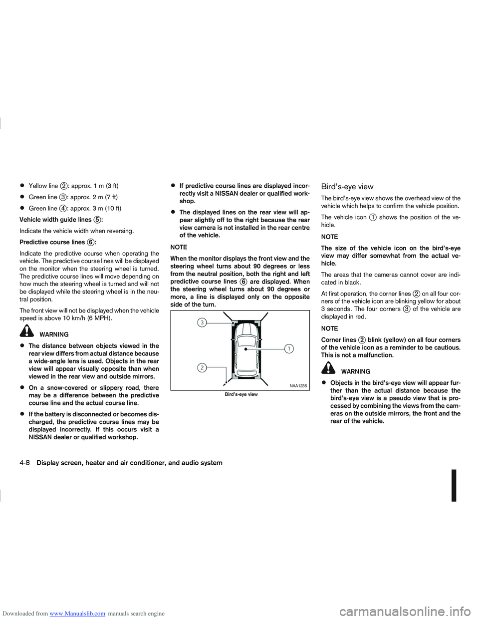
Bird’s-eye view
The bird’s-eye view shows the overhead view of the
vehicle which helps to confirm the vehicle position.
The vehicle icon
j1 shows the position of the ve-
hicle.
NOTE
The size of the vehicle icon on the bird’s-eye
view may differ somewhat from the actual ve-
hicle.
The areas that the cameras cannot cover are indi-
cated in black.
At first operation, the corner lines
j2 on all four cor-
ners of the vehicle icon are blinking yellow for about
3 seconds. The four corners
j3 of the vehicle are
displayed in red.
NOTE
Corner lines
j2 blink (yellow) on all four corners
of the vehicle icon as a reminder to be cautious.
This is not a malfunction.
WARNING
Objects in the bird’s-eye view will appear fur-
ther than the actual distance because the
bird’s-eye view is a pseudo view that is pro-
cessed by combining the views from the cam-
eras on the outside mirrors, the front and the
rear of the vehicle.NAA1236
Bird’s-eye view
4-8Display screen, heater and air conditioner, and audio system
Page 116 of 297
Downloaded from www.Manualslib.com manuals search engine Tall objects, such as a kerb or vehicle, may be
misaligned or not displayed at the seam of
the views.
Objects that are above the camera cannot be
displayed.
The view for the bird’s-eye view may be mis-
aligned when the camera position alters.
A line on the ground may be misaligned and is
not seen as being straight at the seam of the
views. The misalignment will increase as the
line proceeds away from the vehicle.
*: For the Right-Hand Drive (RHD) models, the screen layout will be opposite.
Front-side view
CAUTION
The actual distance to objects may differ from
the distance shown. Guiding lines:
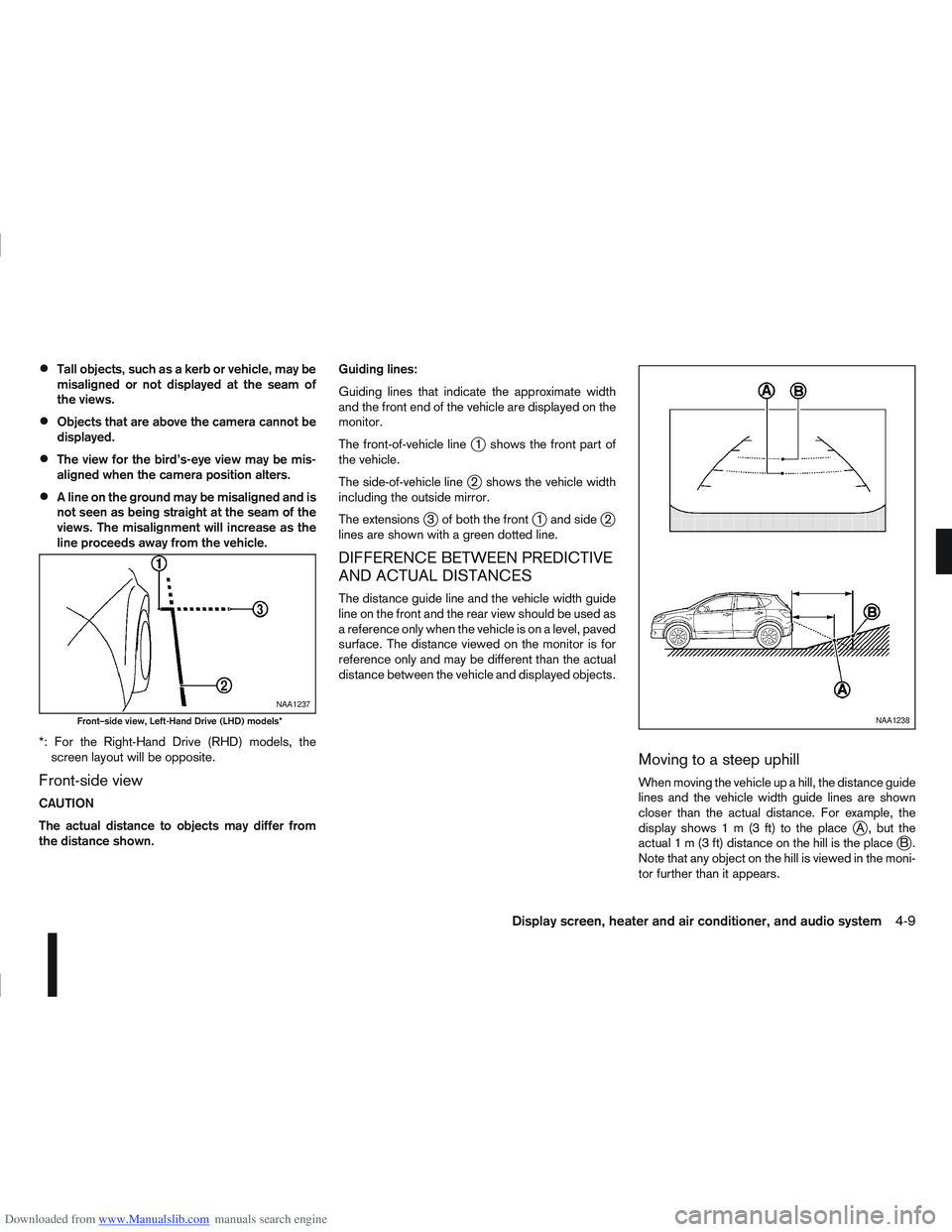
Guiding lines that indicate the approximate width
and the front end of the vehicle are displayed on the
monitor.
The front-of-vehicle line
j1 shows the front part of
the vehicle.
The side-of-vehicle line
j2 shows the vehicle width
including the outside mirror.
The extensions
j3 of both the frontj1 and sidej2
lines are shown with a green dotted line.
DIFFERENCE BETWEEN PREDICTIVE
AND ACTUAL DISTANCES
The distance guide line and the vehicle width guide
line on the front and the rear view should be used as
a reference only when the vehicle is on a level, paved
surface. The distance viewed on the monitor is for
reference only and may be different than the actual
distance between the vehicle and displayed objects.
Moving to a steep uphill
When moving the vehicle up a hill, the distance guide
lines and the vehicle width guide lines are shown
closer than the actual distance. For example, the
display shows 1 m (3 ft) to the place
jA , but the
actual1m(3ft)d istance on the hill is the placejB.
Note that any object on the hill is viewed in the moni-
tor further than it appears.
NAA1237
Front–side view, Left-Hand Drive (LHD) models*NAA1238
Display screen, heater and air conditioner, and audio system4-9
Page 117 of 297
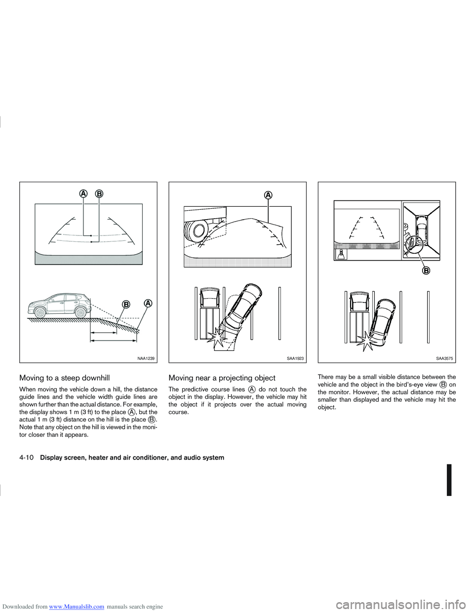
Downloaded from www.Manualslib.com manuals search engine Moving to a steep downhill
When moving the vehicle down a hill, the distance
guide lines and the vehicle width guide lines are
shown further than the actual distance. For example,
thedisplayshows1m(3ft)totheplace
jA , but the
actual 1 m (3 ft) distance on the hill is the placejB.
Note that any object on the hill is viewed in the moni-
tor closer than it appears.
Moving near a projecting object
The predictive course linesjA do not touch the
object in the display. However, the vehicle may hit
the object if it projects over the actual moving
course. There may be a small visible distance between the
vehicle and the object in the bird’s-eye viewjBon
the monitor. However, the actual distance may be
smaller than displayed and the vehicle may hit the
object.
NAA1239SAA1923SAA3575
4-10Display screen, heater and air conditioner, and audio system
Page 118 of 297
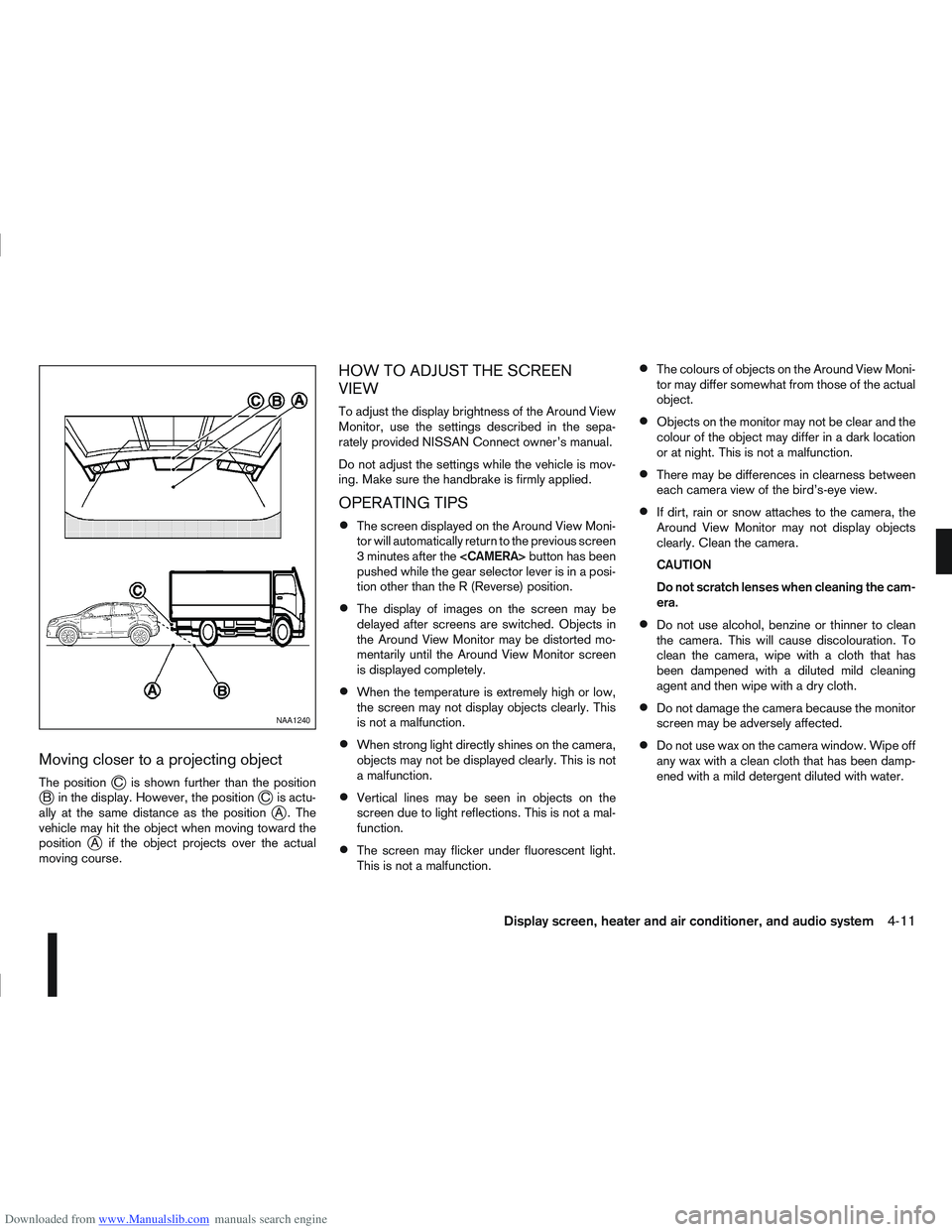
Downloaded from www.Manualslib.com manuals search engine Moving closer to a projecting object
The positionjC is shown further than the positionjB in the display. However, the positionjC is actu-
ally at the same distance as the positionjA . The
vehicle may hit the object when moving toward the
position
jA if the object projects over the actual
moving course.
HOW TO ADJUST THE SCREEN
VIEW
To adjust the display brightness of the Around View
Monitor, use the settings described in the sepa-
rately provided NISSAN Connect owner’s manual.
Do not adjust the settings while the vehicle is mov-
ing. Make sure the handbrake is firmly applied.
OPERATING TIPS
The screen displayed on the Around View Moni-
tor will automatically return to the previous screen
3 minutes after the
pushed while the gear selector lever is in a posi-
tion other than the R (Reverse) position.
The display of images on the screen may be
delayed after screens are switched. Objects in
the Around View Monitor may be distorted mo-
mentarily until the Around View Monitor screen
is displayed completely.
When the temperature is extremely high or low,
the screen may not display objects clearly. This
is not a malfunction.
When strong light directly shines on the camera,
objects may not be displayed clearly. This is not
a malfunction.
Vertical lines may be seen in objects on the
screen due to light reflections. This is not a mal-
function.
The screen may flicker under fluorescent light.
This is not a malfunction.
The colours of objects on the Around View Moni-
tor may differ somewhat from those of the actual
object.
Objects on the monitor may not be clear and the
colour of the object may differ in a dark location
or at night. This is not a malfunction.
There may be differences in clearness between
each camera view of the bird’s-eye view.
If dirt, rain or snow attaches to the camera, the
Around View Monitor may not display objects
clearly. Clean the camera.
CAUTION
Do not scratch lenses when cleaning the cam-
era.
Do not use alcohol, benzine or thinner to clean
the camera. This will cause discolouration. To
clean the camera, wipe with a cloth that has
been dampened with a diluted mild cleaning
agent and then wipe with a dry cloth.
Do not damage the camera because the monitor
screen may be adversely affected.
Do not use wax on the camera window. Wipe off
any wax with a clean cloth that has been damp-
ened with a mild detergent diluted with water.
NAA1240
Display screen, heater and air conditioner, and audio system4-11
Page 119 of 297
Downloaded from www.Manualslib.com manuals search engine SIDE AND CENTRE VENTS
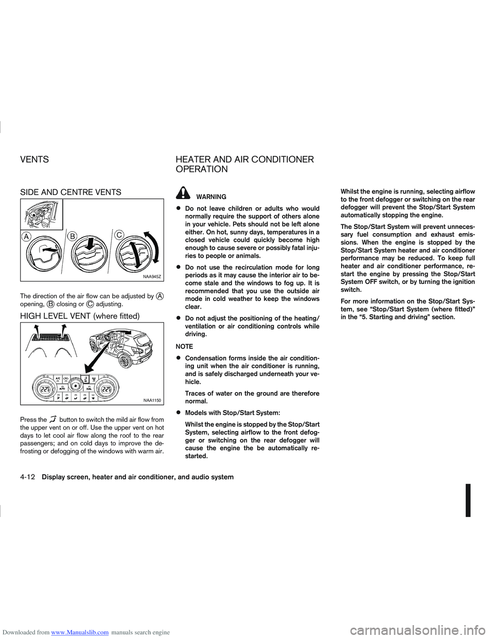
The direction of the air flow can be adjusted byjA
opening,jB closing orjC adjusting.
HIGH LEVEL VENT (where fitted)
Press thebutton to switch the mild air flow from
the upper vent on or off. Use the upper vent on hot
days to let cool air flow along the roof to the rear
passengers; and on cold days to improve the de-
frosting or defogging of the windows with warm air.
WARNING
Do not leave children or adults who would
normally require the support of others alone
in your vehicle. Pets should not be left alone
either. On hot, sunny days, temperatures in a
closed vehicle could quickly become high
enough to cause severe or possibly fatal inju-
ries to people or animals.
Do not use the recirculation mode for long
periods as it may cause the interior air to be-
come stale and the windows to fog up. It is
recommended that you use the outside air
mode in cold weather to keep the windows
clear.
Do not adjust the positioning of the heating/
ventilation or air conditioning controls while
driving.
NOTE
Condensation forms inside the air condition-
ing unit when the air conditioner is running,
and is safely discharged underneath your ve-
hicle.
Traces of water on the ground are therefore
normal.
Models with Stop/Start System:
Whilst the engine is stopped by the Stop/Start
System, selecting airflow to the front defog-
ger or switching on the rear defogger will
cause the engine the be automatically re-
started. Whilst the engine is running, selecting airflow
to the front defogger or switching on the rear
defogger will prevent the Stop/Start System
automatically stopping the engine.
The Stop/Start System will prevent unneces-
sary fuel consumption and exhaust emis-
sions. When the engine is stopped by the
Stop/Start System heater and air conditioner
performance may be reduced. To keep full
heater and air conditioner performance, re-
start the engine by pressing the Stop/Start
System OFF switch, or by turning the ignition
switch.
For more information on the Stop/Start Sys-
tem, see “Stop/Start System (where fitted)”
in the “5. Starting and driving” section.
NAA945Z
NAA1150
VENTS
HEATER AND AIR CONDITIONER
OPERATION
4-12Display screen, heater and air conditioner, and audio system
Page 120 of 297
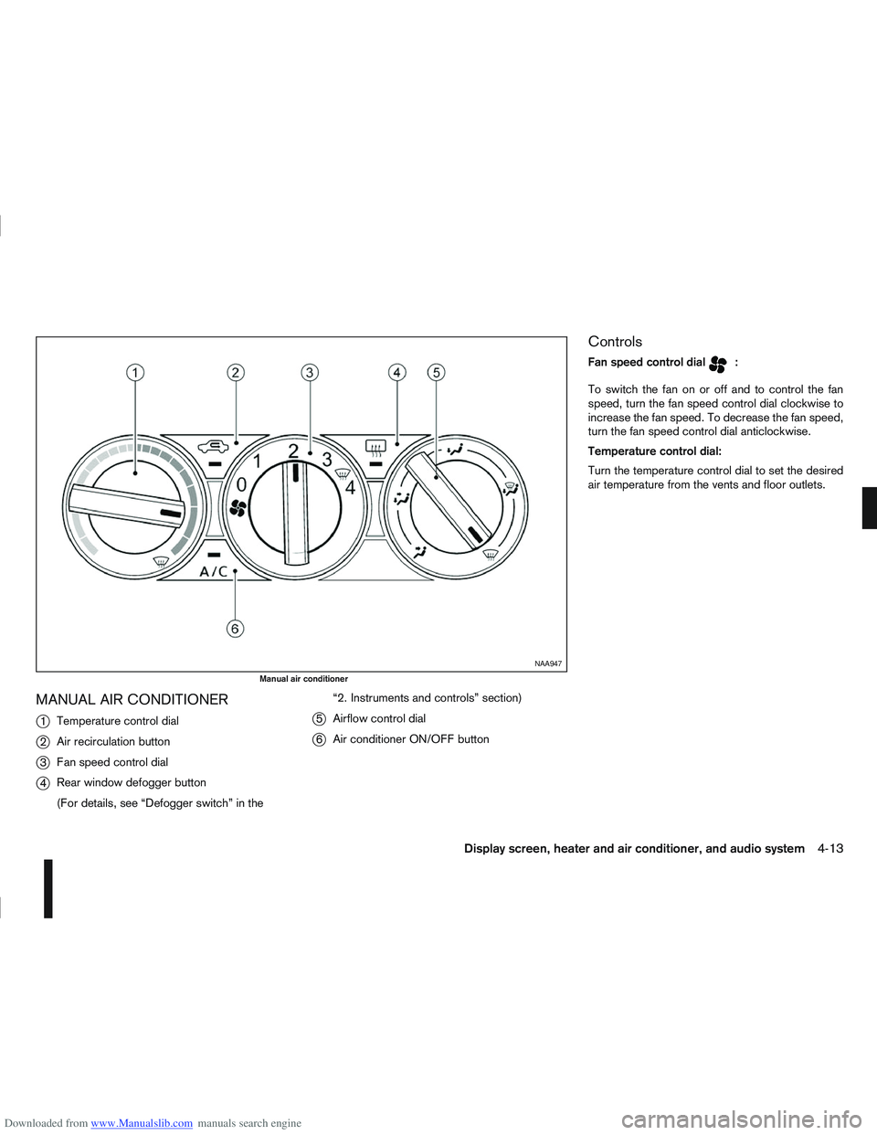
Downloaded from www.Manualslib.com manuals search engine MANUAL AIR CONDITIONER
j
1Temperature control dial
j2Air recirculation button
j3Fan speed control dial
j4Rear window defogger button
(For details, see “Defogger switch” in the “2. Instruments and controls” section)
j5
Airflow control dial
j6Air conditioner ON/OFF button
Controls
Fan speed control dialm:
To switch the fan on or off and to control the fan
speed, turn the fan speed control dial clockwise to
increase the fan speed. To decrease the fan speed,
turn the fan speed control dial anticlockwise.
Temperature control dial:
Turn the temperature control dial to set the desired
air temperature from the vents and floor outlets.
NAA947
Manual air conditioner
Display screen, heater and air conditioner, and audio system4-13
Page 121 of 297
Downloaded from www.Manualslib.com manuals search engine Air flow control dial:
Use this dial to manually select the air flow from the
air outlets as described below.
: Air flows from centre and side vents.
: Air flows from centre, side vents and floor
outlets.
: Air flows mainly from floor outlets.
: Air flows from the defogger outlets and floor
outlets.
: Air flows mainly from defogger outlets.
Air recirculation button
m:
Outside air circulation
Press the air recirculation () button to the
“OFF” position to draw outside air into the pas-
senger compartment (the indicator light goes
off). Use the “OFF” position for normal heating
ventilation, or air conditioner (where fitted) op-
eration.
Air recirculation
Press the air recirculation (
) button to the
“ON” position (the indicator light goes on). Use
the “ON” position in situations such as: driving
on a dust raised road, avoiding traffic fumes or
having maximum cooling from the air conditioner
(where fitted).
If the windows fog up, switch on the air condi-
tioning (where fitted). A/C (Air Conditioner) button (where fitted):
Press the A/C button to turn the air conditioner on
or off. When the air conditioner is on, the A/C indi-
cator light illuminates.
Operation
The heater and air conditioner operate when the
engine is running. The air blower will operate even if
the engine is turned off and the ignition switch is in
the ON position.
NOTE
The air conditioner cooling function operates only
when the engine is running and the fan is acti-
vated.
1. Press the air recirculation (
) button to the
“OFF” position.
2. Turn the airflow control dial for: – Cooling: select the
orposition.
– Heating: select the
orposition.
– Heating and defogging : select the
po-
sition.
– Ventilation : select the
orposition.
– Windscreen defogging : select the
po-
sition
3. Turn the fan speed control dial to the desired position.
4. Turn the temperature control dial to the desired position. NOTE
When selecting the
orposition, turn
the temperature control dial to the desired
position between the middle and the maxi-
mum “HOT” (right) position.
5. Press the A/C button (where fitted) to the “ON” position and the indicator light will come on.
Switch this mode on for dehumidified heating or
cooling.
NOTE
The air conditioner mode is used to cool and
dehumidify. For quick cooling when the out-
side temperature is high, select the air recir-
culation mode position (
). Be sure to re-
turn to the outside air mode to avoid windows
from fogging-up and interior air from becom-
ing stale.
A visible mist may be seen coming from the
vents in hot, humid conditions as the air is
cooled rapidly this is not a malfunction.
For quick heating, press the air recirculation
() button to the “ON” position. Be sure to
return to the “OFF” position for normal heat-
ing (no indicator light) in order to avoid win-
dow fog and stale interior.
To quickly defrost/defog the windscreen,
turn:
1) The airflow control dial to
position.
2) The fan speed control dial to speed posi- tion 4.
4-14Display screen, heater and air conditioner, and audio system
Page 122 of 297
Downloaded from www.Manualslib.com manuals search engine 3) The temperature control dial to the maxi-mum “HOT” (right) position.
Operating tips
In order to improve the heater operation, clear
the snow and ice from the wiper blade and air
inlet in front of the windscreen.
After parking in the sun, drive for two or three
minutes with the windows open to vent hot air
from the passenger compartment. Then close
the windows to allow the acceleration of the air
conditioner’s cooling operation.
Keep the windows closed while the air condi-
tioner is operating.
The air conditioning system should be operated
for about 10 minutes, at least once a month. This
helps prevent damage to the system due to lack
of lubrication.
If the coolant temperature gauge exceeds the
“HOT” position, turn the air conditioner off. For
additional information, see “Engine overheat” in
the “6. In case of emergency” section.
If the engine coolant reaches an extremely high
temperature, the air conditioning system will au-
tomatically turn off. This may happen for example
if the engine runs at idle speed for a long time on
a hot day.
Quick reference charts
The following charts show the button, air intake and
dial positions for MAXIMUM AND QUICK heating,
cooling or defrosting. NOTE
The air recirculation mode should not be selected
for either heating or defrosting.
Display screen, heater and air conditioner, and audio system4-15