2006 NISSAN QASHQAI clock
[x] Cancel search: clockPage 170 of 297
Downloaded from www.Manualslib.com manuals search engine unlock the steering wheel, insert the ignition key and
turn it gently while rotating the steering wheel slightly
right and left.
The ignition key can only be removed when the
switch is in the LOCK position (Normal parking po-
sition) (0).
AUTOMATIC TRANSMISSION OR
CONTINUOUSLY VARIABLE
TRANSMISSION
On Automatic Transmission (AT) or Continuously
Variable Transmission (CVT) models, the ignition
lock is designed so that the key cannot be turned to
LOCK and removed until the selector lever is moved
to the P (Park) position.
When removing the key from the LOCK position of
the ignition switch, make sure that the selector lever
is in the P (Park) position.
The selector lever can only be moved from the P
(Park) position when the ignition switch is in the ON
position and the footbrake pedal is depressed.
To remove the key from the ignition switch:
1. Move the selector lever into the P (Park) posi-tion.
2. Turn the key to the LOCK position.
3. Remove the key from the ignition switch.
If the key is removed from the ignition switch, the
selector lever cannot be moved from the P (Park)
position. When the key cannot be turned toward the LOCK
position, proceed as follows to remove the key:
1. Move the selector lever into the P (Park) posi-
tion.
2. Turn the key slightly in the ON direction.
3. Turn the key towards the LOCK position.
4. Remove the key.
STEERING LOCK
To lock the steering wheel
1. Turn the key to the LOCK position.
2. Remove the key from the ignition switch.
3. Turn the steering wheel 1/6 of a turn clockwise from the straight up position.
To unlock the steering wheel
1. Insert the key into the ignition switch.
2. Gently turn the key while rotating the steeringwheel slightly right and left.
KEY POSITIONS
LOCK (Normal parking position) (0)
The ignition key can only be removed when in this
position.
The steering lock can only be locked in this position.
“OFF” (1)
The engine is turned off without locking the steering
wheel.
Acc (Accessories) (2)
This position activates electrical accessories, such
as the radio, when the engine is not running.
ON (Normal operating position) (3)
This position turns on the ignition system and elec-
trical accessories.
START (4)
The engine starter activates and the engine will start.
As soon as the engine has started, release the key
immediately. It will return to the ON position.
NOTE
For vehicles fitted with Stop/Start System:
When the engine is automatically stopped by the
Stop/Start System the ignition switch can still be
operated as usual.
At the end of a journey turn the ignition OFF to
avoid a flat battery. The Stop/Start System does
not automatically turn ignition off.
NISSAN ANTI-THEFT SYSTEM (NATS)
The NISSAN Anti Theft System (NATS)* will stop
the engine if someone tries to start the engine with-
out using the registered NATS key.
* Immobilizer
If you failed to start the engine using the NATS Key,
turn the ignition knob to the LOCK position, wait for
5 seconds and turn the key to the START position
again to start the engine.
Starting and driving5-7
Page 187 of 297
![NISSAN QASHQAI 2006 Owners Manual Downloaded from www.Manualslib.com manuals search engine – [Total Saving]
Estimated CO2 exhaust emissions pre-
vented.
Time that the engine has been stopped by
the Stop/Start System.
NOTE
The [Total NISSAN QASHQAI 2006 Owners Manual Downloaded from www.Manualslib.com manuals search engine – [Total Saving]
Estimated CO2 exhaust emissions pre-
vented.
Time that the engine has been stopped by
the Stop/Start System.
NOTE
The [Total](/manual-img/5/56770/w960_56770-186.png)
Downloaded from www.Manualslib.com manuals search engine – [Total Saving]
Estimated CO2 exhaust emissions pre-
vented.
Time that the engine has been stopped by
the Stop/Start System.
NOTE
The [Total Saving] values cannot be reset
and show accumulated Stop/Start System
information since the vehicle was built.Ultrasonic sensors
jA , fitted in the vehicle’s rear
bumper, measure the distance between the vehicle
and an obstacle when reversing. When reverse gear
is engaged a beeping sound is heard. The frequency
of the beeps will increase the closer you come to
the obstacle until, the sound becomes a constant
beep when, the vehicle is approximately 30 cm (12
in) from the obstacle.
NOTE
This system is intended as an aid to reversing,
to be used in conjunction with your rear view
mirror.
Make sure that the ultrasonic sensors are not
obscured (by dirt, mud, snow, etc.). The Four Wheel Drive (4WD) system is used to
select 2WD, AUTO, or LOCK depending on the
driving conditions.
The Four Wheel Drive (4WD) system controls the
coupling operation. Turn the control (located on the
centre console) to select each mode: 2WD, AUTO
or LOCK depending on the driving conditions.
AUTO: Turn the 4WD mode control to the neutral
(AUTO) position and the Four-Wheel Drive (4WD)
AUTO indicator light
on the combination meter
illuminates.
2WD: Turn the control clockwise to the 2WD posi-
tion.
LOCK: When the control is turned anticlockwise to
the LOCK position, it springs back to the AUTO
position when released. The 4WD LOCK mode in-
dicator light
illuminates on the combination
meter, to show LOCK mode is engaged. To disen-
gage LOCK mode, turn the control anticlockwise
again to the LOCK position and release. The 4WD
LOCK mode indicator light will go out.
NSD300ZNSD297Z
ULTRASONIC PARKING SENSOR
(where fitted) FOUR-WHEEL DRIVE (4WD)
(where fitted)
5-24Starting and driving
Page 210 of 297
Downloaded from www.Manualslib.com manuals search engine 6. Turn off the engine.
7. Open the bonnet (for details, see “Bonnetrelease” in the “3. Pre-driving checks and
adjustments” section) in order to:
Warn other traffic.
Signal to professional road assistance that
you require assistance.
8. Have all passengers exit the vehicle and stand in a safe place, away from traffic and clear of the
vehicle.
CHANGING FLAT TYRE (Models with
spare wheel, where fitted)
Blocking the wheels
WARNING
Make sure to block the appropriate wheel to pre-
vent the vehicle from moving, which may cause
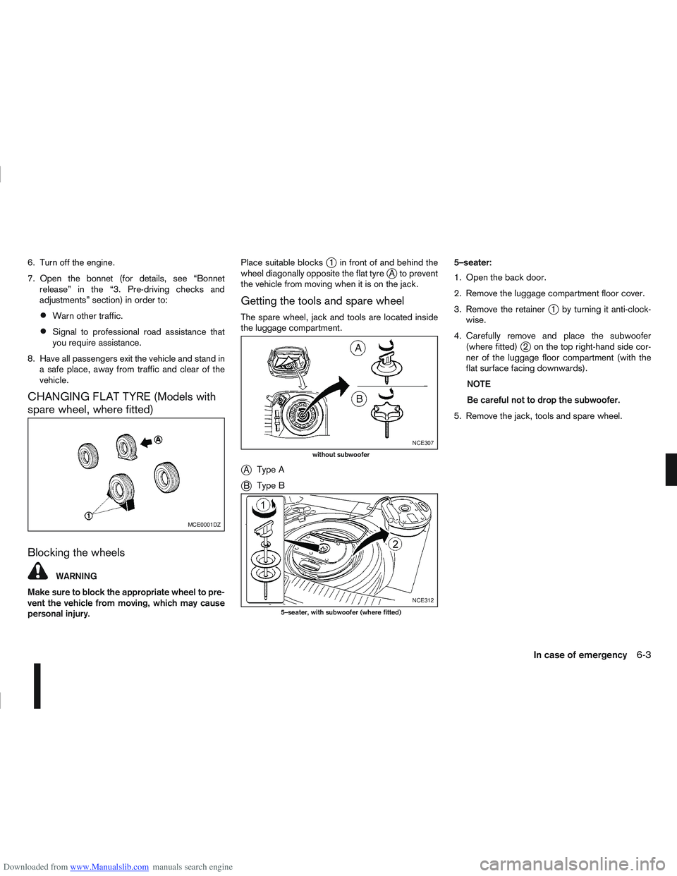
personal injury. Place suitable blocks
j1 in front of and behind the
wheel diagonally opposite the flat tyrejA to prevent
the vehicle from moving when it is on the jack.
Getting the tools and spare wheel
The spare wheel, jack and tools are located inside
the luggage compartment.
jA Type A
jB Type B 5–seater:
1. Open the back door.
2. Remove the luggage compartment floor cover.
3. Remove the retainer
j1 by turning it anti-clock-
wise.
4. Carefully remove and place the subwoofer (where fitted)
j2 on the top right-hand side cor-
ner of the luggage floor compartment (with the
flat surface facing downwards).
NOTE
Be careful not to drop the subwoofer.
5. Remove the jack, tools and spare wheel.
MCE0001DZ
NCE307
without subwoofer
NCE312
5–seater, with subwoofer (where fitted)
In case of emergency6-3
Page 212 of 297
Downloaded from www.Manualslib.com manuals search engine Never allow passengers to stay in the vehicle
while it is on the jack.
Remove all loads before lifting the vehicle with
the jack.
Make sure to block the wheel diagonally op-
posite the flat tyre as described earlier in this
section.
CAUTION
The jack should be used on firm, level ground.
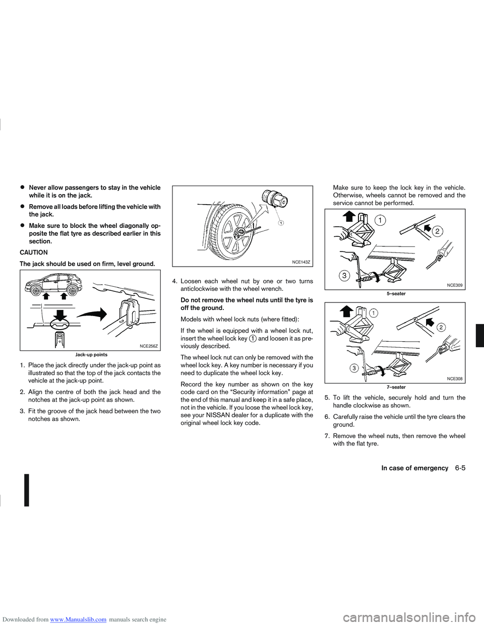
1. Place the jack directly under the jack-up point as illustrated so that the top of the jack contacts the
vehicle at the jack-up point.
2. Align the centre of both the jack head and the notches at the jack-up point as shown.
3. Fit the groove of the jack head between the two notches as shown. 4. Loosen each wheel nut by one or two turns
anticlockwise with the wheel wrench.
Do not remove the wheel nuts until the tyre is
off the ground.
Models with wheel lock nuts (where fitted):
If the wheel is equipped with a wheel lock nut,
insert the wheel lock key
j1 and loosen it as pre-
viously described.
The wheel lock nut can only be removed with the
wheel lock key. A key number is necessary if you
need to duplicate the wheel lock key.
Record the key number as shown on the key
code card on the “Security information” page at
the end of this manual and keep it in a safe place,
not in the vehicle. If you loose the wheel lock key,
see your NISSAN dealer for a duplicate with the
original wheel lock key code. Make sure to keep the lock key in the vehicle.
Otherwise, wheels cannot be removed and the
service cannot be performed.
5. To lift the vehicle, securely hold and turn the handle clockwise as shown.
6. Carefully raise the vehicle until the tyre clears the ground.
7. Remove the wheel nuts, then remove the wheel with the flat tyre.NCE256Z
Jack-up points
NCE143Z
NCE309
5–seater
NCE308
7–seater
In case of emergency6-5
Page 214 of 297
Downloaded from www.Manualslib.com manuals search engine 2. Store the subwoofer (where fitted) as it was origi-nally installed.
3. Install the retainer and replace the floor cover.
7–seater
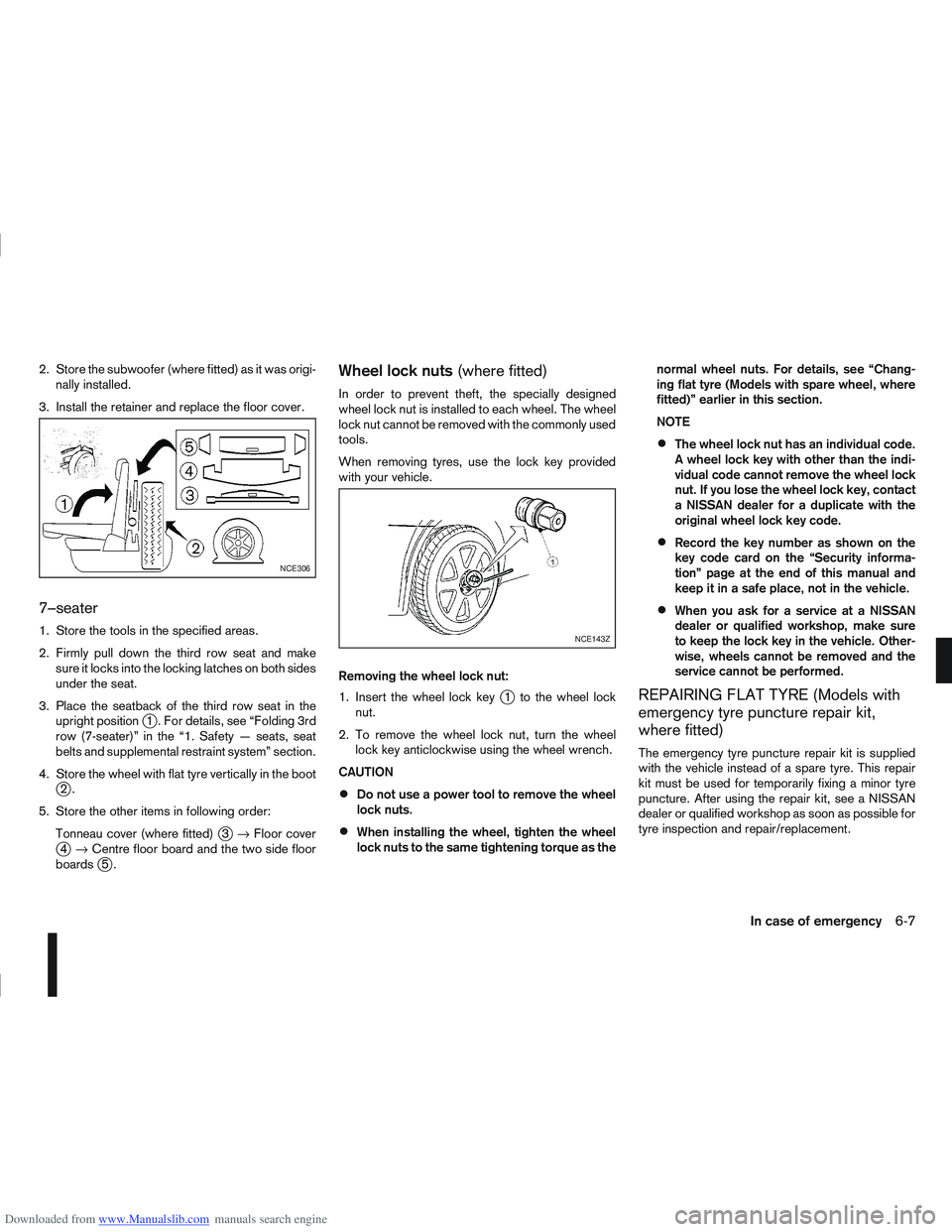
1. Store the tools in the specified areas.
2. Firmly pull down the third row seat and make sure it locks into the locking latches on both sides
under the seat.
3. Place the seatback of the third row seat in the upright position
j1 . For details, see “Folding 3rd
row (7-seater)” in the “1. Safety — seats, seat
belts and supplemental restraint system” section.
4. Store the wheel with flat tyre vertically in the boot
j2.
5. Store the other items in following order: Tonneau cover (where fitted)
j3→ Floor coverj4→ Centre floor board and the two side floor
boardsj5.
Wheel lock nuts (where fitted)
In order to prevent theft, the specially designed
wheel lock nut is installed to each wheel. The wheel
lock nut cannot be removed with the commonly used
tools.
When removing tyres, use the lock key provided
with your vehicle.
Removing the wheel lock nut:
1. Insert the wheel lock key
j1 to the wheel lock
nut.
2. To remove the wheel lock nut, turn the wheel lock key anticlockwise using the wheel wrench.
CAUTION
Do not use a power tool to remove the wheel
lock nuts.
When installing the wheel, tighten the wheel
lock nuts to the same tightening torque as the normal wheel nuts. For details, see “Chang-
ing flat tyre (Models with spare wheel, where
fitted)” earlier in this section.
NOTE
The wheel lock nut has an individual code.
A wheel lock key with other than the indi-
vidual code cannot remove the wheel lock
nut. If you lose the wheel lock key, contact
a NISSAN dealer for a duplicate with the
original wheel lock key code.
Record the key number as shown on the
key code card on the “Security informa-
tion” page at the end of this manual and
keep it in a safe place, not in the vehicle.
When you ask for a service at a NISSAN
dealer or qualified workshop, make sure
to keep the lock key in the vehicle. Other-
wise, wheels cannot be removed and the
service cannot be performed.
REPAIRING FLAT TYRE (Models with
emergency tyre puncture repair kit,
where fitted)
The emergency tyre puncture repair kit is supplied
with the vehicle instead of a spare tyre. This repair
kit must be used for temporarily fixing a minor tyre
puncture. After using the repair kit, see a NISSAN
dealer or qualified workshop as soon as possible for
tyre inspection and repair/replacement.
NCE306
NCE143Z
In case of emergency6-7
Page 249 of 297
Downloaded from www.Manualslib.com manuals search engine Battery (Type A)
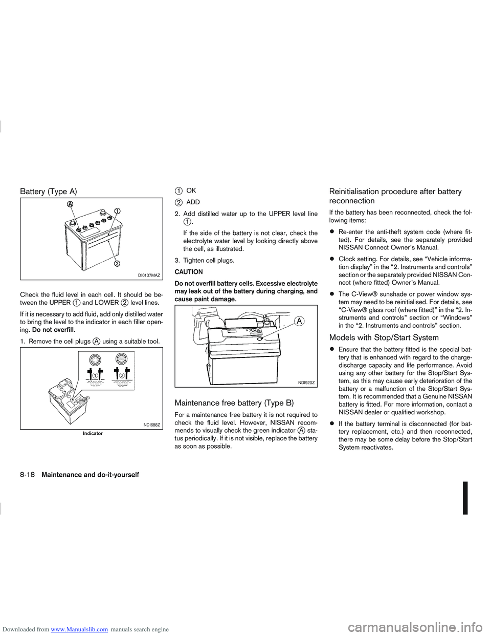
Check the fluid level in each cell. It should be be-
tween the UPPERj1 and LOWERj2 level lines.
If it is necessary to add fluid, add only distilled water
to bring the level to the indicator in each filler open-
ing. Do not overfill.
1. Remove the cell plugs
jA using a suitable tool.
j1 OK
j2ADD
2. Add distilled water up to the UPPER level line
j1.
If the side of the battery is not clear, check the
electrolyte water level by looking directly above
the cell, as illustrated.
3. Tighten cell plugs.
CAUTION
Do not overfill battery cells. Excessive electrolyte
may leak out of the battery during charging, and
cause paint damage.
Maintenance free battery (Type B)
For a maintenance free battery it is not required to
check the fluid level. However, NISSAN recom-
mends to visually check the green indicator
jA sta-
tus periodically. If it is not visible, replace the battery
as soon as possible.
Reinitialisation procedure after battery
reconnection
If the battery has been reconnected, check the fol-
lowing items:
Re-enter the anti-theft system code (where fit-
ted). For details, see the separately provided
NISSAN Connect Owner’s Manual.
Clock setting. For details, see “Vehicle informa-
tion display” in the “2. Instruments and controls”
section or the separately provided NISSAN Con-
nect (where fitted) Owner’s Manual.
The C-View® sunshade or power window sys-
tem may need to be reinitialised. For details, see
“C-View® glass roof (where fitted)” in the “2. In-
struments and controls” section or “Windows”
in the “2. Instruments and controls” section.
Models with Stop/Start System
Ensure that the battery fitted is the special bat-
tery that is enhanced with regard to the charge-
discharge capacity and life performance. Avoid
using any other battery for the Stop/Start Sys-
tem, as this may cause early deterioration of the
battery or a malfunction of the Stop/Start Sys-
tem. It is recommended that a Genuine NISSAN
battery is fitted. For more information, contact a
NISSAN dealer or qualified workshop.
If the battery terminal is disconnected (for bat-
tery replacement, etc.) and then reconnected,
there may be some delay before the Stop/Start
System reactivates.
DI0137MAZ
NDI688Z
Indicator
NDI920Z
8-18Maintenance and do-it-yourself
Page 254 of 297
Downloaded from www.Manualslib.com manuals search engine BACK DOOR WINDOW WIPER
REPLACEMENT
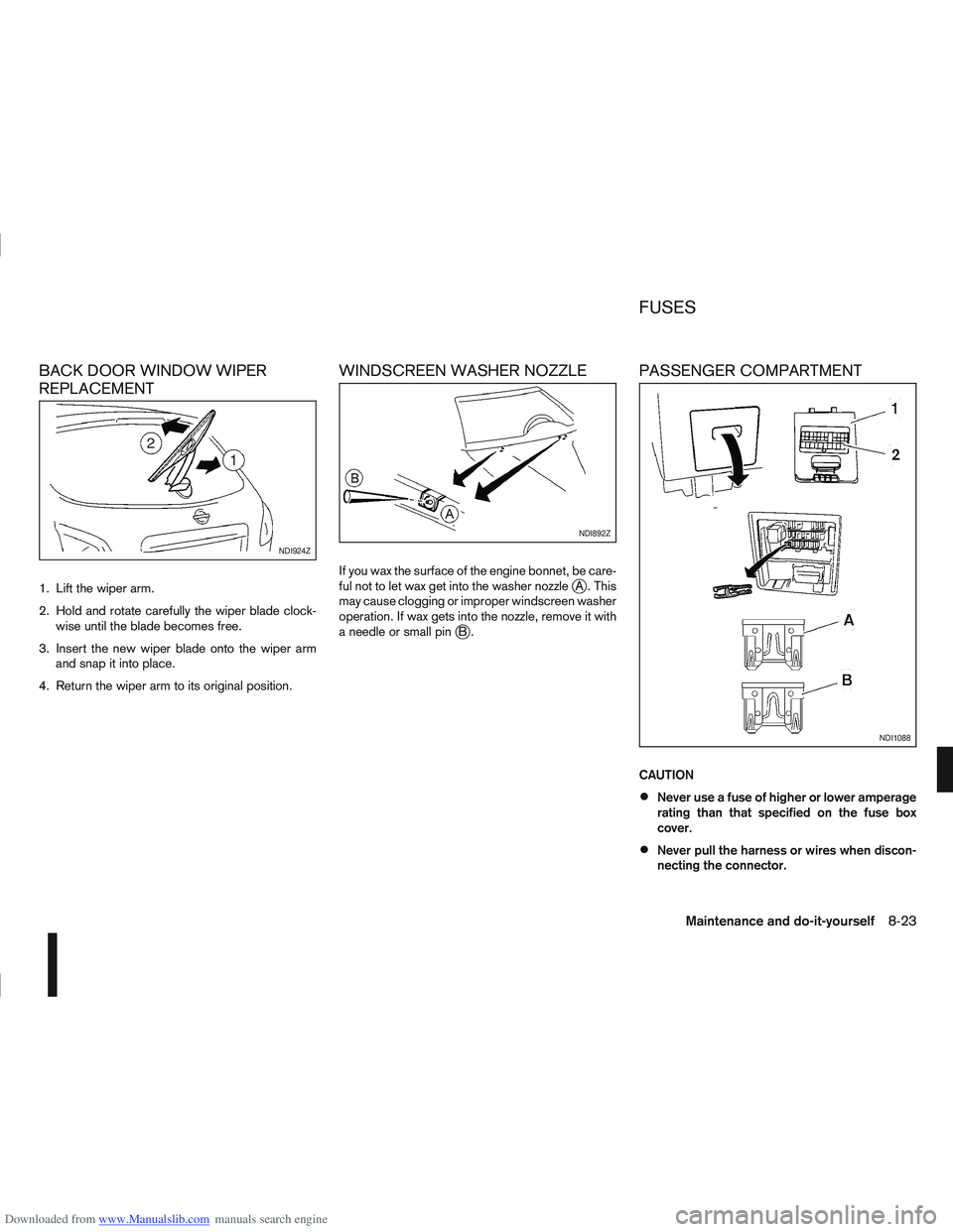
1. Lift the wiper arm.
2. Hold and rotate carefully the wiper blade clock-wise until the blade becomes free.
3. Insert the new wiper blade onto the wiper arm and snap it into place.
4. Return the wiper arm to its original position.
WINDSCREEN WASHER NOZZLE
If you wax the surface of the engine bonnet, be care-
ful not to let wax get into the washer nozzlejA . This
may cause clogging or improper windscreen washer
operation. If wax gets into the nozzle, remove it with
aneedleorsmallpin
jB.
PASSENGER COMPARTMENT
CAUTION
Never use a fuse of higher or lower amperage
rating than that specified on the fuse box
cover.
Never pull the harness or wires when discon-
necting the connector.
NDI924Z
NDI892Z
NDI1088
FUSES
Maintenance and do-it-yourself8-23
Page 257 of 297
Downloaded from www.Manualslib.com manuals search engine Only hold the xenon headlight bulb by the
base.
The bulb is manufactured from high-quality
quartz and is under high pressure.
Damage, soiling, and fingerprints should be
avoided and, if necessary, removed with alco-
hol before installing the bulb.
When the headlights are switched on, the
bulbs produce a certain amount of UV radia-
tion. In order to avoid any impairment of health
(burning and conjunctivitis), the bulb should
only be used in closed headlights with appro-
priate UV–absorbing front glass.
Due to the risk of burning, the bulb should be
left to cool down for 3 minutes after switching
off before touching.
Due to the use of mercury and various salts,
the bulb should be treated as special waste
when discarded.
The bulb may only be operated with a suitable
ballast which produces very high voltages
when switched on and during operation.
Contact with bulb and wires should therefore
be avoided and a safe distance of at least 30
mm should be maintained.
Replacing the halogen headlight bulb
CAUTION
High pressure halogen gas is sealed inside
the halogen bulb. The bulb may break if the
glass envelope is scratched or the bulb is
dropped.
When handling the bulb, DO NOT TOUCH THE
GLASS ENVELOPE.
Use the same number type and wattage as
originally installed.
Aiming is usually not necessary after replac-
ing the bulb. When aiming adjustment is nec-
essary, contact a NISSAN dealer or qualified
workshop.
Do not leave the bulb out of the headlight
reflector for a long period of time as dust,
moisture or smoke may enter the headlight
body and affect the performance of the head-
light.
The headlight is a semi-sealed beam type which
uses a replaceable headlight (halogen) bulb. A bulb
can be replaced from inside the engine compart-
ment without removing the headlight assembly.
Contact a NISSAN dealer or qualified workshop, if
you need assistance for bulb replacement.
1. Open the bonnet. For details, see “Bonnet release” in the “3. Pre-driving checks and
adjustments” section.
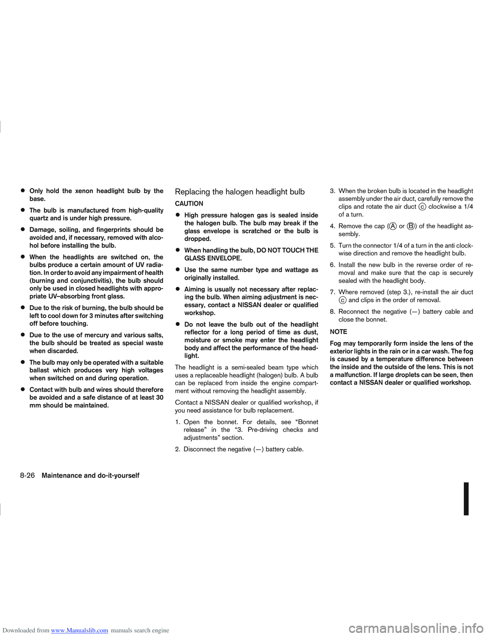
2. Disconnect the negative (—) battery cable. 3. When the broken bulb is located in the headlight
assembly under the air duct, carefully remove the
clips and rotate the air duct
jc clockwise a 1/4
of a turn.
4. Remove the cap (
jAorjB ) of the headlight as-
sembly.
5. Turn the connector 1/4 of a turn in the anti clock- wise direction and remove the headlight bulb.
6. Install the new bulb in the reverse order of re- moval and make sure that the cap is securely
sealed with the headlight body.
7. Where removed (step 3.), re-install the air duct
jc and clips in the order of removal.
8. Reconnect the negative (—) battery cable and close the bonnet.
NOTE
Fog may temporarily form inside the lens of the
exterior lights in the rain or in a car wash. The fog
is caused by a temperature difference between
the inside and the outside of the lens. This is not
a malfunction. If large droplets can be seen, then
contact a NISSAN dealer or qualified workshop.
8-26Maintenance and do-it-yourself