Page 1091 of 1226
Electrical Components Inspection
DIFFERENTIAL LOCK INDICATOR SWITCH CHECK
+Check switch function by checking continuity.
Continuity:
ON Continuity should exist.
OFF Continuity should not exist.
If NG, replace differential lock indicator switch.
DIFFERENTIAL LOCK SOLENOID CHECK
1. Disconnect differential lock solenoid 4-pin connector.
2. Check continuity between terminals
V1andV3,V2andV4.
Continuity should exist.
If NG, replace differential lock solenoid.
SPEED SENSOR CHECK
Refer to EL section.
SPD443A
SPD444A
DIFFERENTIAL LOCK
PD-49
Page 1092 of 1226

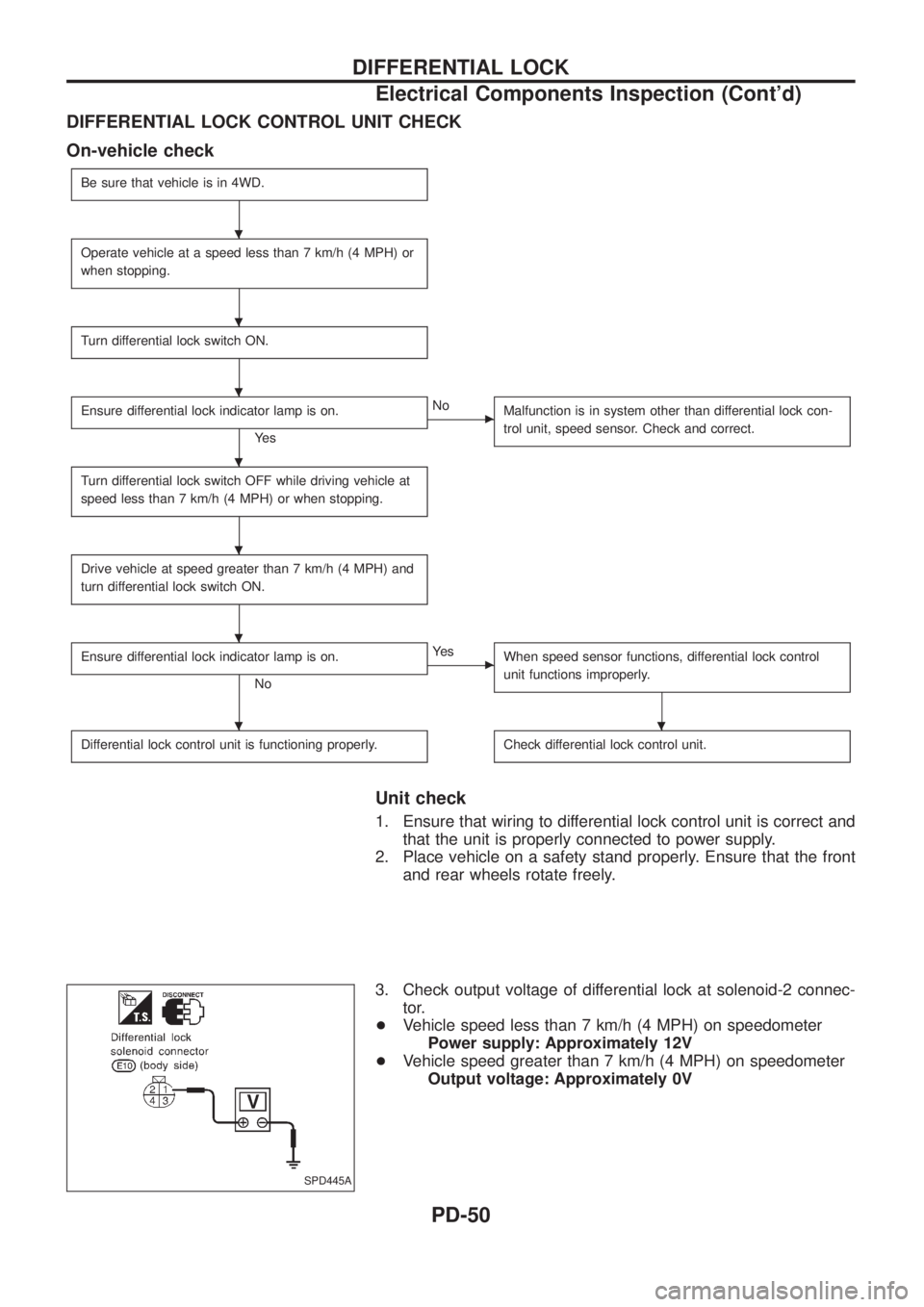
DIFFERENTIAL LOCK CONTROL UNIT CHECK
On-vehicle check
Be sure that vehicle is in 4WD.
Operate vehicle at a speed less than 7 km/h (4 MPH) or
when stopping.
Turn differential lock switch ON.
Ensure differential lock indicator lamp is on.
Ye s
cNo
Malfunction is in system other than differential lock con-
trol unit, speed sensor. Check and correct.
Turn differential lock switch OFF while driving vehicle at
speed less than 7 km/h (4 MPH) or when stopping.
Drive vehicle at speed greater than 7 km/h (4 MPH) and
turn differential lock switch ON.
Ensure differential lock indicator lamp is on.
No
cYe s
When speed sensor functions, differential lock control
unit functions improperly.
Differential lock control unit is functioning properly.Check differential lock control unit.
Unit check
1. Ensure that wiring to differential lock control unit is correct and
that the unit is properly connected to power supply.
2. Place vehicle on a safety stand properly. Ensure that the front
and rear wheels rotate freely.
3. Check output voltage of differential lock at solenoid-2 connec-
tor.
+Vehicle speed less than 7 km/h (4 MPH) on speedometer
Power supply: Approximately 12V
+Vehicle speed greater than 7 km/h (4 MPH) on speedometer
Output voltage: Approximately 0V
SPD445A
.
.
.
.
.
.
..
DIFFERENTIAL LOCK
Electrical Components Inspection (Cont'd)
PD-50
Page 1094 of 1226

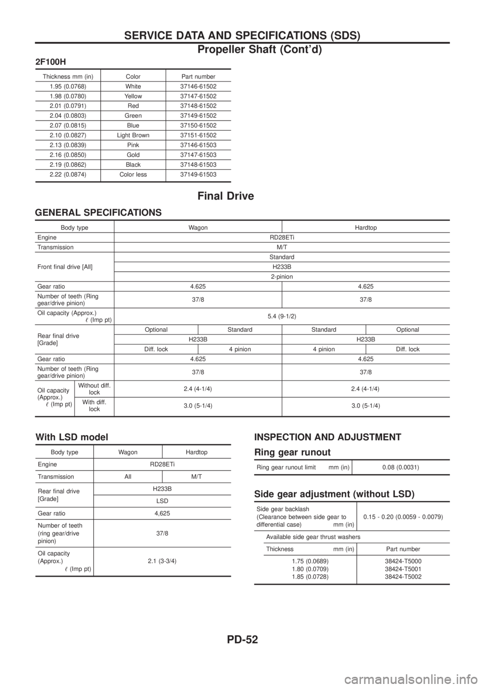
2F100H
Thickness mm (in) Color Part number1.95 (0.0768) White 37146-61502
1.98 (0.0780) Yellow 37147-61502
2.01 (0.0791) Red 37148-61502
2.04 (0.0803) Green 37149-61502
2.07 (0.0815) Blue 37150-61502
2.10 (0.0827) Light Brown 37151-61502
2.13 (0.0839) Pink 37146-61503
2.16 (0.0850) Gold 37147-61503
2.19 (0.0862) Black 37148-61503
2.22 (0.0874) Color less 37149-61503
Final Drive
GENERAL SPECIFICATIONS
Body type Wagon Hardtop
Engine RD28ETi
Transmission M/T
Front ®nal drive [All] Standard
H233B
2-pinion
Gear ratio 4.625 4.625
Number of teeth (Ring
gear/drive pinion) 37/8 37/8
Oil capacity (Approx.) !(Imp pt) 5.4 (9-1/2)
Rear ®nal drive
[Grade] Optional Standard Standard Optional
H233B H233B
Diff. lock 4 pinion 4 pinion Diff. lock
Gear ratio 4.625 4.625
Number of teeth (Ring
gear/drive pinion) 37/8 37/8
Oil capacity
(Approx.) !(Imp pt) Without diff.
lock 2.4 (4
-1/4)2.4 (4-1/4)
With diff.lock 3.0 (5-1/4) 3.0 (5-1/4)
With LSD model
Body type Wagon Hardtop
Engine RD28ETi
Transmission All M/T
Rear ®nal drive
[Grade] H233B
LSD
Gear ratio 4,625
Number of teeth
(ring gear/drive
pinion) 37/8
Oil capacity
(Approx.) !(Imp pt) 2.1 (3-3/4)
INSPECTION AND ADJUSTMENT
Ring gear runout
Ring gear runout limit mm (in) 0.08 (0.0031)
Side gear adjustment (without LSD)
Side gear backlash
(Clearance between side gear to
differential case) mm (in) 0.15 - 0.20 (0.0059 - 0.0079)
Available side gear thrust washers
Thickness mm (in) Part number 1.75 (0.0689)
1.80 (0.0709)
1.85 (0.0728) 38424-T5000
38424-T5001
38424-T5002
SERVICE DATA AND SPECIFICATIONS (SDS)
Propeller Shaft (Cont'd)
PD-52
Page 1172 of 1226

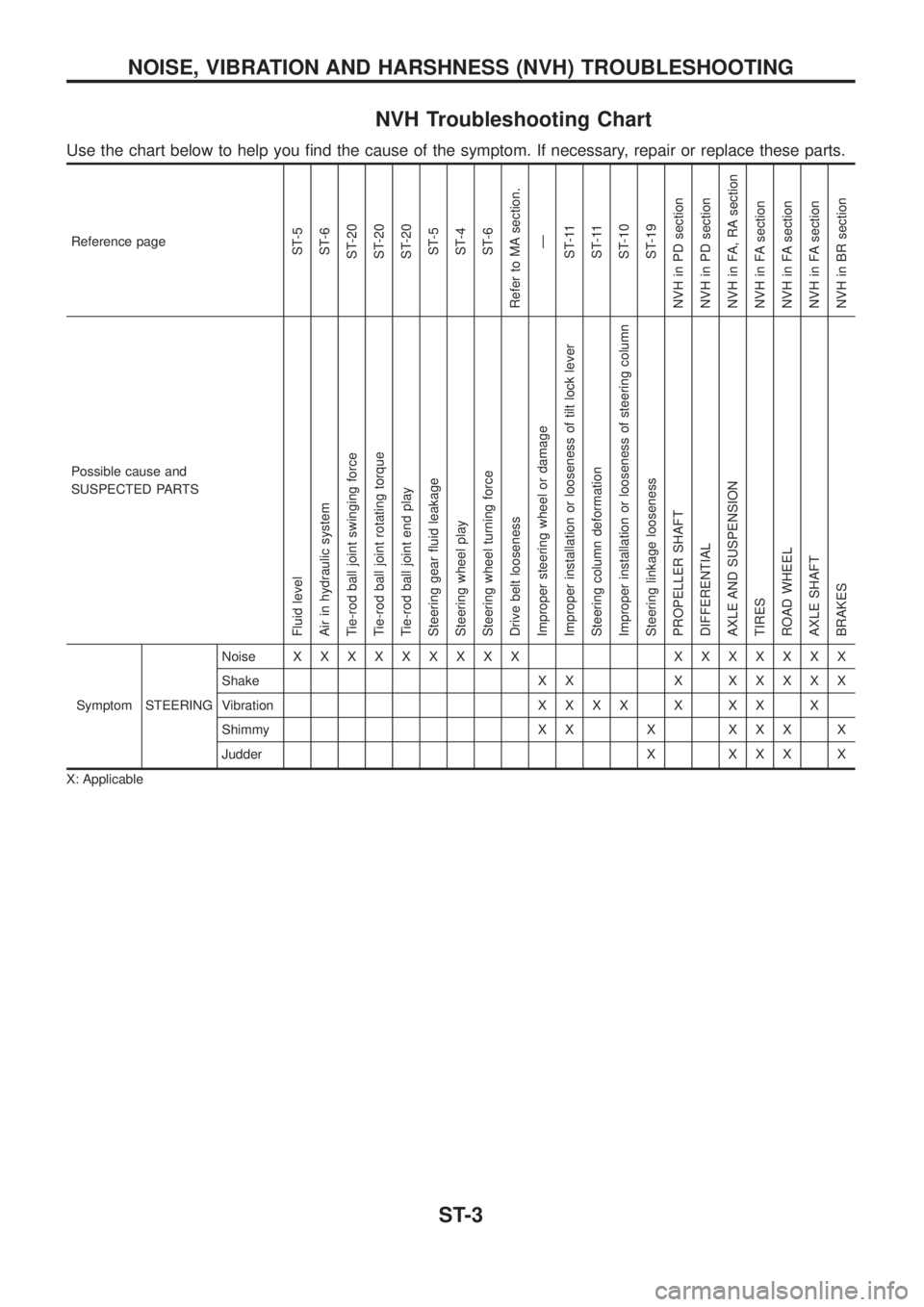
NVH Troubleshooting Chart
Use the chart below to help you ®nd the cause of the symptom. If necessary, repair or replace these parts.
Reference pageST-5
ST-6
ST-20
ST-20
ST-20
ST-5
ST-4
ST-6
Refer to MA section.
Ð
ST-11
ST-11
ST-10
ST-19
NVH in PD section
NVH in PD section
NVH in FA, RA section
NVH in FA section
NVH in FA section
NVH in FA section
NVH in BR section
Possible cause and
SUSPECTED PARTS
Fluid level
Air in hydraulic system
Tie-rod ball joint swinging force
Tie-rod ball joint rotating torque
Tie-rod ball joint end play
Steering gear ¯uid leakage
Steering wheel play
Steering wheel turning force
Drive belt looseness
Improper steering wheel or damage
Improper installation or looseness of tilt lock lever
Steering column deformation
Improper installation or looseness of steering column
Steering linkage looseness
PROPELLER SHAFT
DIFFERENTIAL
AXLE AND SUSPENSION
TIRES
ROAD WHEEL
AXLE SHAFT
BRAKES
Symptom STEERINGNoiseXXXXXXXXX XXXXXXX
Shake X X XXXXXX
VibrationXXXXXXXX
Shimmy X X X X X X X
Judder X X X X X
X: Applicable
NOISE, VIBRATION AND HARSHNESS (NVH) TROUBLESHOOTING
ST-3