2006 NISSAN PATROL Coolant temperature
[x] Cancel search: Coolant temperaturePage 872 of 1226
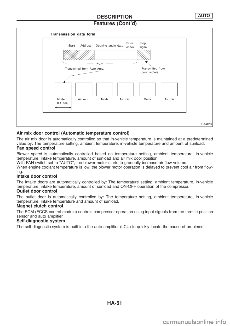
Air mix door control (Automatic temperature control)
The air mix door is automatically controlled so that in-vehicle temperature is maintained at a predetermined
value by: The temperature setting, ambient temperature, in-vehicle temperature and amount of sunload.
Fan speed control
Blower speed is automatically controlled based on temperature setting, ambient temperature, in-vehicle
temperature, intake temperature, amount of sunload and air mix door position.
With FAN switch set to ``AUTO'', the blower motor starts to gradually increase air ¯ow volume.
When engine coolant temperature is low, the blower motor operation is delayed to prevent cool air from ¯ow-
ing.
Intake door control
The intake doors are automatically controlled by: The temperature setting, ambient temperature, in-vehicle
temperature, intake temperature, amount of sunload and ON-OFF operation of the compressor.
Outlet door control
The outlet door is automatically controlled by: The temperature setting, ambient temperature, in-vehicle
temperature, intake temperature and amount of sunload.
Magnet clutch control
The ECM (ECCS control module) controls compressor operation using input signals from the throttle position
sensor and auto ampli®er.
Self-diagnostic system
The self-diagnostic system is built into the auto ampli®er (LCU) to quickly locate the cause of problems.
RHA442G
DESCRIPTIONAUTO
Features (Cont'd)
HA-51
Page 908 of 1226
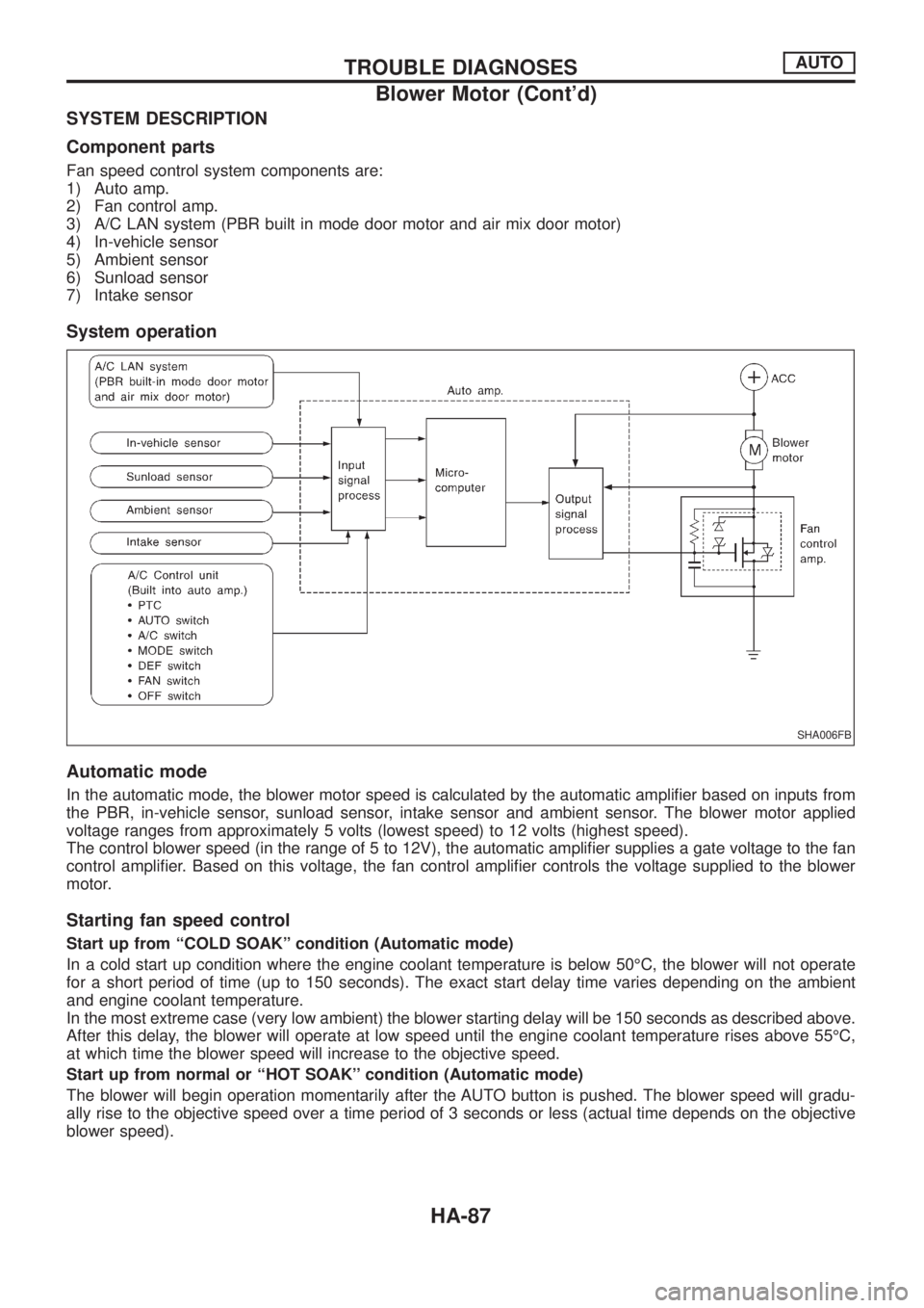
SYSTEM DESCRIPTION
Component parts
Fan speed control system components are:
1) Auto amp.
2) Fan control amp.
3) A/C LAN system (PBR built in mode door motor and air mix door motor)
4) In-vehicle sensor
5) Ambient sensor
6) Sunload sensor
7) Intake sensor
System operation
Automatic mode
In the automatic mode, the blower motor speed is calculated by the automatic ampli®er based on inputs from
the PBR, in-vehicle sensor, sunload sensor, intake sensor and ambient sensor. The blower motor applied
voltage ranges from approximately 5 volts (lowest speed) to 12 volts (highest speed).
The control blower speed (in the range of 5 to 12V), the automatic ampli®er supplies a gate voltage to the fan
control ampli®er. Based on this voltage, the fan control ampli®er controls the voltage supplied to the blower
motor.
Starting fan speed control
Start up from ``COLD SOAK'' condition (Automatic mode)
In a cold start up condition where the engine coolant temperature is below 50ÉC, the blower will not operate
for a short period of time (up to 150 seconds). The exact start delay time varies depending on the ambient
and engine coolant temperature.
In the most extreme case (very low ambient) the blower starting delay will be 150 seconds as described above.
After this delay, the blower will operate at low speed until the engine coolant temperature rises above 55ÉC,
at which time the blower speed will increase to the objective speed.
Start up from normal or ``HOT SOAK'' condition (Automatic mode)
The blower will begin operation momentarily after the AUTO button is pushed. The blower speed will gradu-
ally rise to the objective speed over a time period of 3 seconds or less (actual time depends on the objective
blower speed).
SHA006FB
TROUBLE DIAGNOSESAUTO
Blower Motor (Cont'd)
HA-87
Page 950 of 1226

Combination meter........................................EL-102
Combination switch .........................................EL-57
Combustion chamber replacement ................EM-32
Compass .......................................................EL-116
Compression pressure ...................................EM-10
Compressor special service tool ......................HA-6
Connecting rod...............................................EM-47
Connecting rod...............................................EM-51
Connector inspection .......................................GI-17
Console box - See Instrument panel ..............BT-11
Control lever (Transfer) .....................................TF-9
Control sleeve position sensor .......................EC-86
Coolant mixture ratio ......................................MA-11
Coolant replacement ......................................MA-14
Cooling circuit (engine) .....................................LC-9
Cooling fan control .......................................EC-112
Cooling fan motor .........................................EC-120
Cooling fan relay ..........................................EC-120
Cooling fan......................................................LC-15
Counter gear (M/T).........................................MT-10
Counter gear (Transfer) ..................................TF-11
Coupling sleeve (M/T) ....................................MT-10
Crankcase emission control system -
See Positive crankcase ventilation.............EC-21
Crankcase ventilation system - See
Positive crankcase ventilation ....................EC-21
Crankshaft position sensor (TDC)................EC-143
Crankshaft ......................................................EM-50
Cylinder block ..........................................EM-45, 48
Cylinder head .................................................EM-28
D
D/LOCK - Wiring diagram .............................EL-205
DEF - Wiring diagram ...................................EL-159
DEICER - Wiring diagram.............................EL-167
DTRL - Wiring diagram ...................................EL-67
Data link connector for Consult......................EC-36
Daytime light system.......................................EL-65
Diagnosis sensor unit .....................................RS-12
Diagnostic trouble code (DTC) for
ECCS OBD system ....................................EC-30
Differential carrier assembly...........................PD-31
Differential carrier disassembly ......................PD-14
Differential gear oil replacement ....................MA-22
Dimensions ......................................................GI-38
Dome light - See Interior lamp .......................EL-93
Door glass .........................................................BT-9
Door lock ...........................................................BT-9
Door mirror ......................................................BT-46
Door trim .........................................................BT-18
Door, front .........................................................BT-9
Door, rear ........................................................BT-10
Drive belt inspection ......................................MA-12
Drive chain (Transfer) .....................................TF-11
Drive pinion diff. inspection ............................PD-19
Drive pinion height .........................................PD-27
Drive shaft (front) ............................................FA-23
Dual pressure switch ......................................HA-11Dual pressure switch ......................................HA-97
E
ECCS basic inspection...................................EC-46
ECCS circuit diagram .....................................EC-11
ECCS component parts location ......................EC-8
ECCS on board diagnostic system ................EC-30
ECCS symptom matrix chart..........................EC-48
ECCS system diagram and chart ..................EC-12
ECCS-D control module .........................EC-54, 110
ECM input/output signal .................................EC-54
ECTS - Wiring diagram ..................................EC-78
EGR control (EGRC) - solenoid valve .........EC-155
EGR control valve ........................................EC-161
EGRC/V - Wiring diagram ............................EC-155
Electric governor ....................................EC-95, 148
Electric sunroof .............................................EL-186
Electrical diagnoses.........................................GI-20
Electrical unit.................................................EL-321
Electrical units location .................................EL-269
Electronic fuel injection pump ........................EC-27
Engine compartment .......................................BT-49
Engine coolant temperature sensor
(ECTS) ........................................................EC-78
Engine oil ®lter replacement ..........................MA-14
Engine oil precautions .......................................GI-4
Engine oil replacement ..................................MA-13
Engine outer component parts ........................EM-8
Engine removal ..............................................EM-43
Engine room - See Engine
compartment ...............................................BT-49
Engine serial number ......................................GI-37
Exhaust system inspection ............................MA-20
Exhaust system ................................................FE-3
Exterior ............................................................BT-26
F
FCUT - Wiring diagram ................................EC-129
FTS - Wiring diagram ...................................EC-134
Fan control amp. ............................................HA-88
Final drive disassembly ..................................PD-14
Final drive removal and installation................PD-11
Finisher, interior - See Trim ............................BT-14
Floor trim .........................................................BT-14
Flow charts ......................................................GI-30
Fluids................................................................MA-9
Flywheel (clutch).......................................CL-13, 14
Flywheel runout..............................................EM-52
Fog lamp, rear ................................................EL-80
Fork rod (M/T) ................................................MT-12
Front axle ........................................................FA-10
Front bumper ....................................................BT-4
Front case (Transfer) ......................................TF-10
Front disc brake .............................................BR-20
Front door .........................................................BT-9
ALPHABETICAL INDEX
IDX-3
Page 959 of 1226
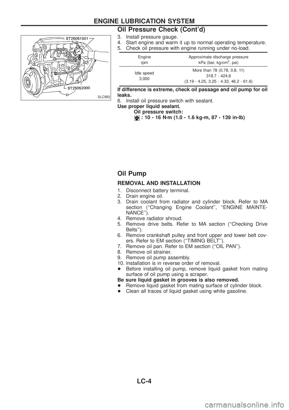
3. Install pressure gauge.
4. Start engine and warm it up to normal operating temperature.
5. Check oil pressure with engine running under no-load.
Engine
rpmApproximate discharge pressure
kPa (bar, kg/cm2, psi)
Idle speed
3,000More than 78 (0.78, 0.8, 11)
318.7 - 424.6
(3.19 - 4.25, 3.25 - 4.33, 46.2 - 61.6)
If difference is extreme, check oil passage and oil pump for oil
leaks.
6. Install oil pressure switch with sealant.
Use proper liquid sealant.
Oil pressure switch:
:10-16Nzm (1.0 - 1.6 kg-m, 87 - 139 in-lb)
Oil Pump
REMOVAL AND INSTALLATION
1. Disconnect battery terminal.
2. Drain engine oil.
3. Drain coolant from radiator and cylinder block. Refer to MA
section (``Changing Engine Coolant'', ``ENGINE MAINTE-
NANCE'').
4. Remove radiator shroud.
5. Remove drive belts. Refer to MA section (``Checking Drive
Belts'').
6. Remove crankshaft pulley and front upper and lower belt cov-
ers. Refer to EM section (``TIMING BELT'').
7. Remove oil pan. Refer to EM section (``OIL PAN'').
8. Remove oil strainer.
9. Remove oil pump assembly.
10. Installation is in reverse order of removal.
+Before installing oil pump, remove liquid gasket from mating
surface of oil pump using a scraper.
Be sure liquid gasket in grooves is also removed.
+Remove liquid gasket from mating surface of cylinder block.
+Clean all traces of liquid gasket using white gasoline.
SLC993
ENGINE LUBRICATION SYSTEM
Oil Pressure Check (Cont'd)
LC-4
Page 988 of 1226
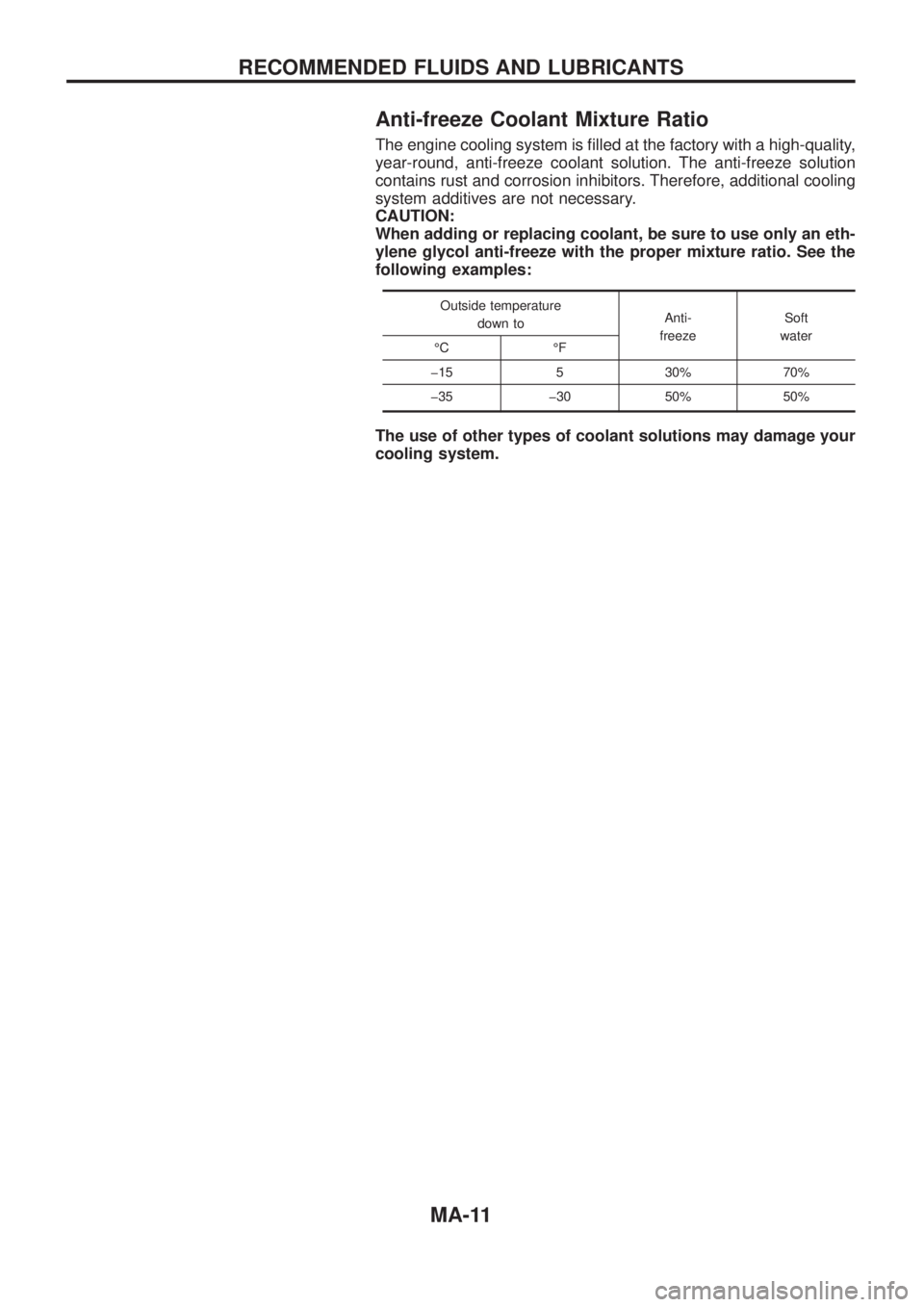
Anti-freeze Coolant Mixture Ratio
The engine cooling system is ®lled at the factory with a high-quality,
year-round, anti-freeze coolant solution. The anti-freeze solution
contains rust and corrosion inhibitors. Therefore, additional cooling
system additives are not necessary.
CAUTION:
When adding or replacing coolant, be sure to use only an eth-
ylene glycol anti-freeze with the proper mixture ratio. See the
following examples:
Outside temperature
down toAnti-
freezeSoft
water
ÉC ÉF
þ15 5 30% 70%
þ35 þ30 50% 50%
The use of other types of coolant solutions may damage your
cooling system.
RECOMMENDED FLUIDS AND LUBRICANTS
MA-11
Page 992 of 1226
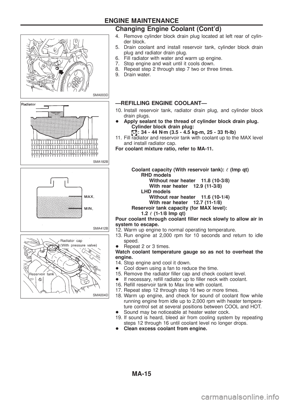
4. Remove cylinder block drain plug located at left rear of cylin-
der block.
5. Drain coolant and install reservoir tank, cylinder block drain
plug and radiator drain plug.
6. Fill radiator with water and warm up engine.
7. Stop engine and wait until it cools down.
8. Repeat step 2 through step 7 two or three times.
9. Drain water.
ÐREFILLING ENGINE COOLANTÐ
10. Install reservoir tank, radiator drain plug, and cylinder block
drain plugs.
+Apply sealant to the thread of cylinder block drain plug.
Cylinder block drain plug:
:34-44Nzm (3.5 - 4.5 kg-m, 25 - 33 ft-lb)
11. Fill radiator and reservoir tank with coolant up to the MAX level
and install radiator cap.
For coolant mixture ratio, refer to MA-11.
Coolant capacity (With reservoir tank):!(Imp qt)
RHD models
Without rear heater 11.8 (10-3/8)
With rear heater 12.9 (11-3/8)
LHD models
Without rear heater 11.6 (10-1/4)
With rear heater 12.7 (11-1/8)
Reservoir tank capacity (for MAX level):
1.2!(1-1/8 Imp qt)
Pour coolant through coolant ®ller neck slowly to allow air in
system to escape.
12. Warm up engine to normal operating temperature.
13. Run engine at 2,000 rpm for 10 seconds and return to idle
speed.
+Repeat 2 or 3 times.
Watch coolant temperature gauge so as not to overheat the
engine.
14. Stop engine and cool it down.
+Cool down using a fan to reduce the time.
15. Remove the radiator ®ller cap and check coolant level.
+If necessary, re®ll radiator up to ®ller neck with coolant.
16. Re®ll reservoir tank to Max line with coolant.
17. Repeat step 12 through step 16 two or more times.
18. Warm up engine, and check for sound of coolant ¯ow while
running engine from idle up to 2,000 rpm with heater tempera-
ture control set at several positions between COOL and HOT.
+Sound may be noticeable at heater water cock.
19. If sound is heard, bleed air from cooling system by repeating
steps 12 through 16 until coolant level no longer drops.
+Clean excess coolant from engine.
SMA003D
SMA182B
SMA412B
SMA004D
ENGINE MAINTENANCE
Changing Engine Coolant (Cont'd)
MA-15
Page 996 of 1226
6. Install all injection nozzles with Tool and securely connect fuel
spill tube and delivery tubes.
7. Bleed air from fuel system and check for fuel leakage with
engine running.
Injection nozzle to cylinder head:
:59-69Nzm (6.0 - 7.0 kg-m, 43 - 51 ft-lb)
Spill tube nut:
:39-49Nzm (4.0 - 5.0 kg-m, 29 - 36 ft-lb)
Injection tube:
:20-25Nzm (2.2 - 2.5 kg-m, 16 - 18 ft-lb)
Checking Idle Speed
Inspection should be carried out with gears in ``Neutral'' and
with air conditioner and other electrical loads off.
1. Warm up engine until engine coolant temperature indicator
points to the middle of gauge.
2. Attach a diesel tachotester's pick-up to No. 1 fuel injection tube.
3. Race engine two or three times and check idle speed.
Idle speed:
Unit: rpm
MT 750+50
þ0
Timing Belt Replacement
Refer to EM section.
ENGINE MAINTENANCE
Checking Injection Nozzle (Cont'd)
MA-19