2006 NISSAN PATROL Coolant temperature
[x] Cancel search: Coolant temperaturePage 302 of 1226
Glow Control System
SYSTEM DESCRIPTION
Crankshaft position sensor (TDC)cEngine speed
ECMcGlow relaycGlow plugs
Engine coolant temperature sensorcEngine coolant temperaturecGlow lamp
When engine coolant temperature is more than 90ÉC (194ÉF), the glow relay turns off, inactivating the quick-
glow control until coolant temperature drops below 70ÉC (158ÉF).
When coolant temperature is lower than 90ÉC (194ÉF):
+Ignition switch ON
After ignition switch has turned to ON, the glow relay turns ON for a certain period of time in relation to
engine coolant temperature, allowing current to ¯ow through glow plug.
+Cranking
The glow relay turns ON, allowing current to ¯ow through glow plug.
+Starting
After engine has started, current continues to ¯ow through glow plug (after-glow mode) for a certain period
in relation to engine coolant temperature.
When engine speed exceeds 2,400 rpm, current ¯ow through glow plug is interrupted.
The glow lamp turns ON for a certain period of time in relation to engine coolant temperature at the time glow
relay is turned ON.
COMPONENT DESCRIPTION
Glow plug
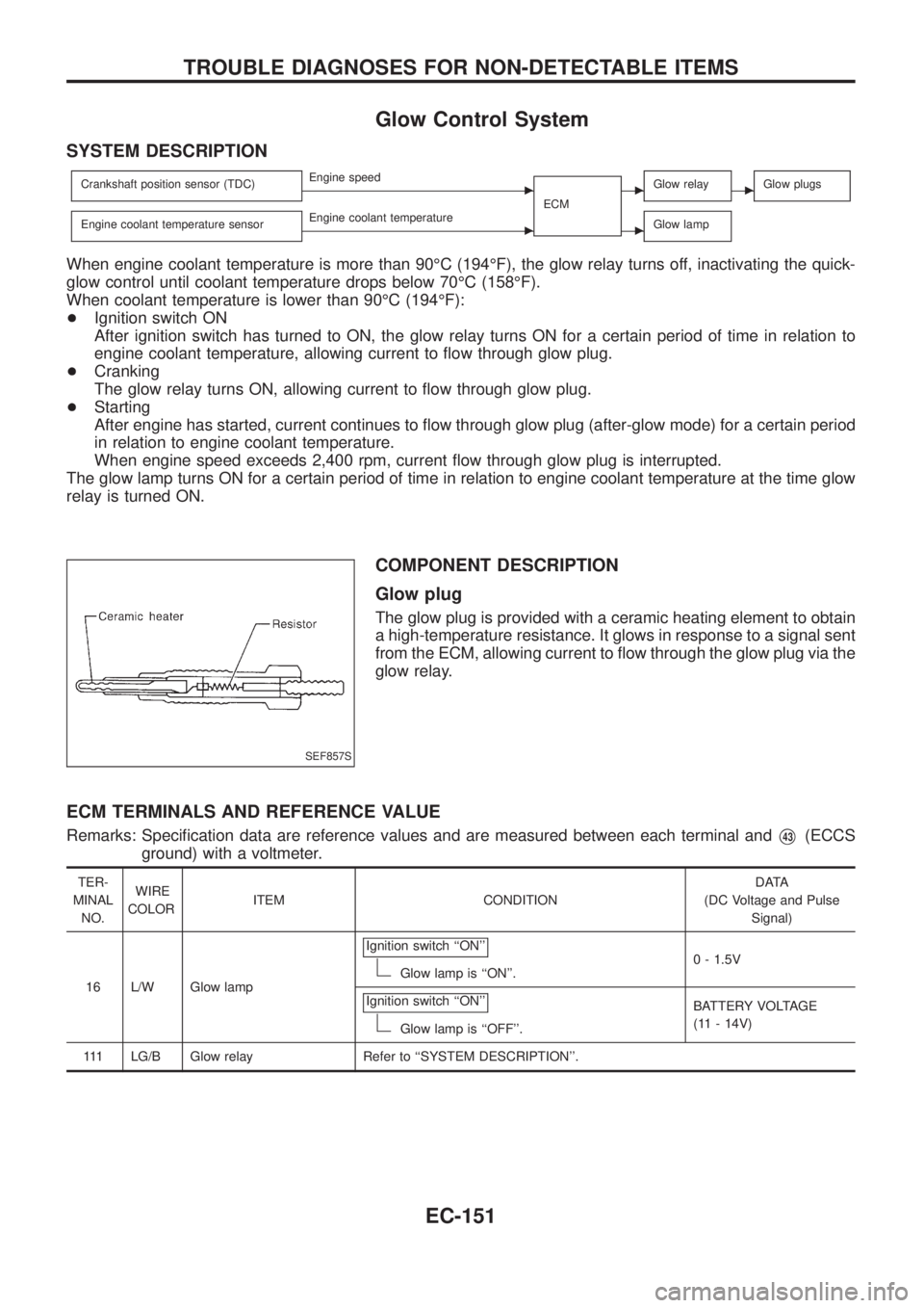
The glow plug is provided with a ceramic heating element to obtain
a high-temperature resistance. It glows in response to a signal sent
from the ECM, allowing current to ¯ow through the glow plug via the
glow relay.
ECM TERMINALS AND REFERENCE VALUE
Remarks: Speci®cation data are reference values and are measured between each terminal andV43(ECCS
ground) with a voltmeter.
TER-
MINAL
NO.WIRE
COLORITEM CONDITIONDATA
(DC Voltage and Pulse
Signal)
16 L/W Glow lampIgnition switch ``ON''
Glow lamp is ``ON''.0 - 1.5V
Ignition switch ``ON''
Glow lamp is ``OFF''.BATTERY VOLTAGE
(11 - 14V)
111 LG/B Glow relay Refer to ``SYSTEM DESCRIPTION''.
SEF857S
TROUBLE DIAGNOSES FOR NON-DETECTABLE ITEMS
EC-151
Page 305 of 1226
jA
CHECK COMPONENTS
(Glow relay, Glow plug).
Refer to ``COMPONENT INSPECTION'',
EC-155.
OK
cNG
Replace malfunctioning
component(s).
Disconnect and reconnect harness connec-
tors in the circuit. Then retest.
Trouble is not ®xed.
Check ECM pin terminals for damage and
check the connection of ECM harness con-
nector. Reconnect ECM harness connector
and retest.
INSPECTION END
SYSTEM OPERATION CHECK
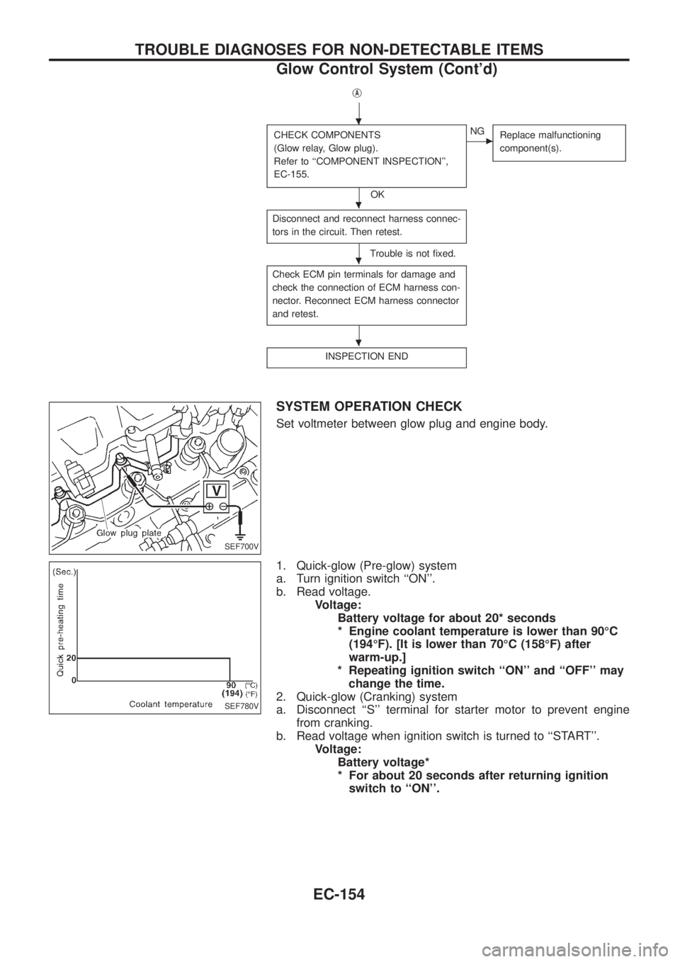
Set voltmeter between glow plug and engine body.
1. Quick-glow (Pre-glow) system
a. Turn ignition switch ``ON''.
b. Read voltage.
Voltage:
Battery voltage for about 20* seconds
* Engine coolant temperature is lower than 90ÉC
(194ÉF). [It is lower than 70ÉC (158ÉF) after
warm-up.]
* Repeating ignition switch ``ON'' and ``OFF'' may
change the time.
2. Quick-glow (Cranking) system
a. Disconnect ``S'' terminal for starter motor to prevent engine
from cranking.
b. Read voltage when ignition switch is turned to ``START''.
Voltage:
Battery voltage*
* For about 20 seconds after returning ignition
switch to ``ON''.
SEF700V
SEF780V
.
.
.
.
TROUBLE DIAGNOSES FOR NON-DETECTABLE ITEMS
Glow Control System (Cont'd)
EC-154
Page 306 of 1226
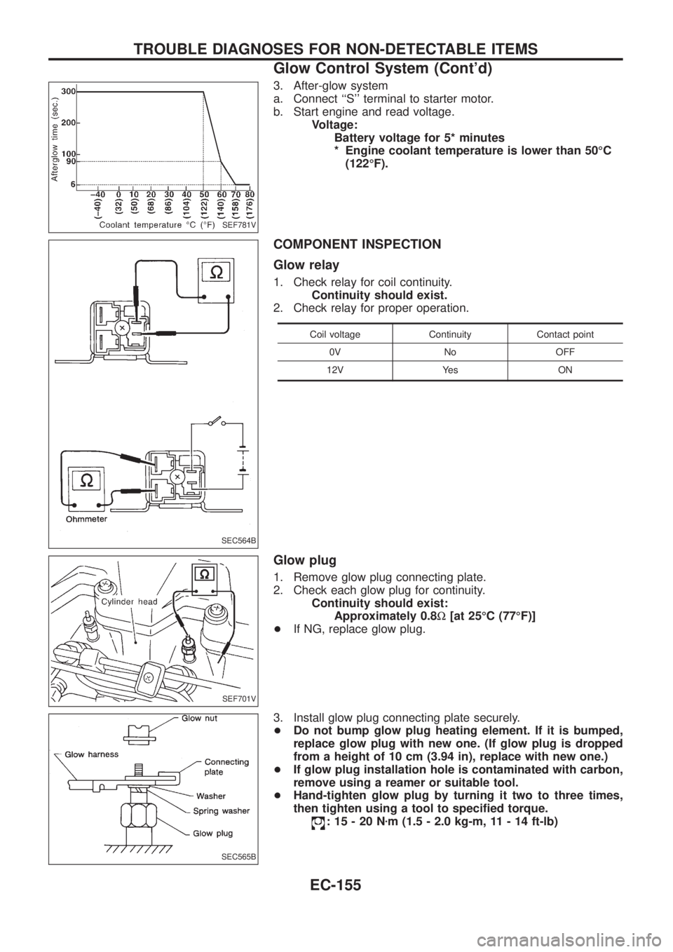
3. After-glow system
a. Connect ``S'' terminal to starter motor.
b. Start engine and read voltage.
Voltage:
Battery voltage for 5* minutes
* Engine coolant temperature is lower than 50ÉC
(122ÉF).
COMPONENT INSPECTION
Glow relay
1. Check relay for coil continuity.
Continuity should exist.
2. Check relay for proper operation.
Coil voltage Continuity Contact point
0V No OFF
12V Yes ON
Glow plug
1. Remove glow plug connecting plate.
2. Check each glow plug for continuity.
Continuity should exist:
Approximately 0.8W[at 25ÉC (77ÉF)]
+If NG, replace glow plug.
3. Install glow plug connecting plate securely.
+Do not bump glow plug heating element. If it is bumped,
replace glow plug with new one. (If glow plug is dropped
from a height of 10 cm (3.94 in), replace with new one.)
+If glow plug installation hole is contaminated with carbon,
remove using a reamer or suitable tool.
+Hand-tighten glow plug by turning it two to three times,
then tighten using a tool to speci®ed torque.
:15-20Nzm (1.5 - 2.0 kg-m, 11 - 14 ft-lb)
SEF781V
SEC564B
SEF701V
SEC565B
TROUBLE DIAGNOSES FOR NON-DETECTABLE ITEMS
Glow Control System (Cont'd)
EC-155
Page 307 of 1226
EGRC-Solenoid Valve A, B and Throttle Control
Solenoid Valve
SYSTEM DESCRIPTION
Camshaft position sensor (TDC)cEngine speed
ECM
(ECCS-D
control
module)cEGRC-solenoid valve A
Accelerator position sensorcAccelerator positioncEGRC-solenoid valve B
Engine coolant temperature sensorcEngine coolant temperaturecThrottle control solenoid valve
Ignition switchcStart signal
Mass air ¯ow sensor
cAmount of intake air
The ECM receives signals sent from the engine coolant tempera-
ture sensor, crankshaft position sensor (TDC), ignition switch, mass
air ¯ow sensor and accelerator position sensor to determine engine
speed and operating conditions. Based on these signals, the ECM
controls EGR control solenoid valve (A and B) operation and
throttle control solenoid valve operation.
Engine coolant
temperature
ÉC (ÉF)LoadEGRC-solenoid valve
Throttle control
solenoid valveEGR valveThrottle control
valveAmount of EGR
gas
AB
Below 70 (158) AnyOFF
(Closed)OFF
(Closed)OFF
(Closed)Fully closed Fully open Ð
Above 70 (158)Low loadON
(Open)ON
(Open)ON
(Open)Fully open Closed Large
Medium load-1ON
(Open)ON
(Open)OFF
(Closed)Fully open Fully open Medium
Medium load-2ON
(Open)OFF
(Closed)OFF
(Closed)Half open Fully open Small
High loadOFF
(Closed)OFF
(Closed)OFF
(Closed)Fully closed Fully open Ð
COMPONENT DESCRIPTION
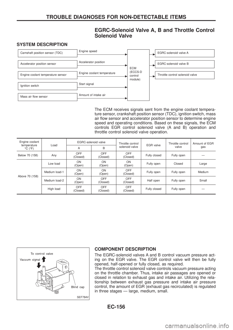
The EGRC-solenoid valves A and B control vacuum pressure act-
ing on the EGR valve. The EGR control valve will then be fully
opened, half-opened or fully closed, as required.
The throttle control solenoid valve controls vacuum pressure acting
on the throttle chamber. Thus, intake air passages are opened or
closed in relation to exhaust gas and intake air. Utilizing the rela-
tionship between exhaust gas pressure and intake air pressure
control, the amount of EGR (exhaust gas recirculated) is regulated
in three stages Ð large, medium, small.
SEF784V
TROUBLE DIAGNOSES FOR NON-DETECTABLE ITEMS
EC-156
Page 334 of 1226
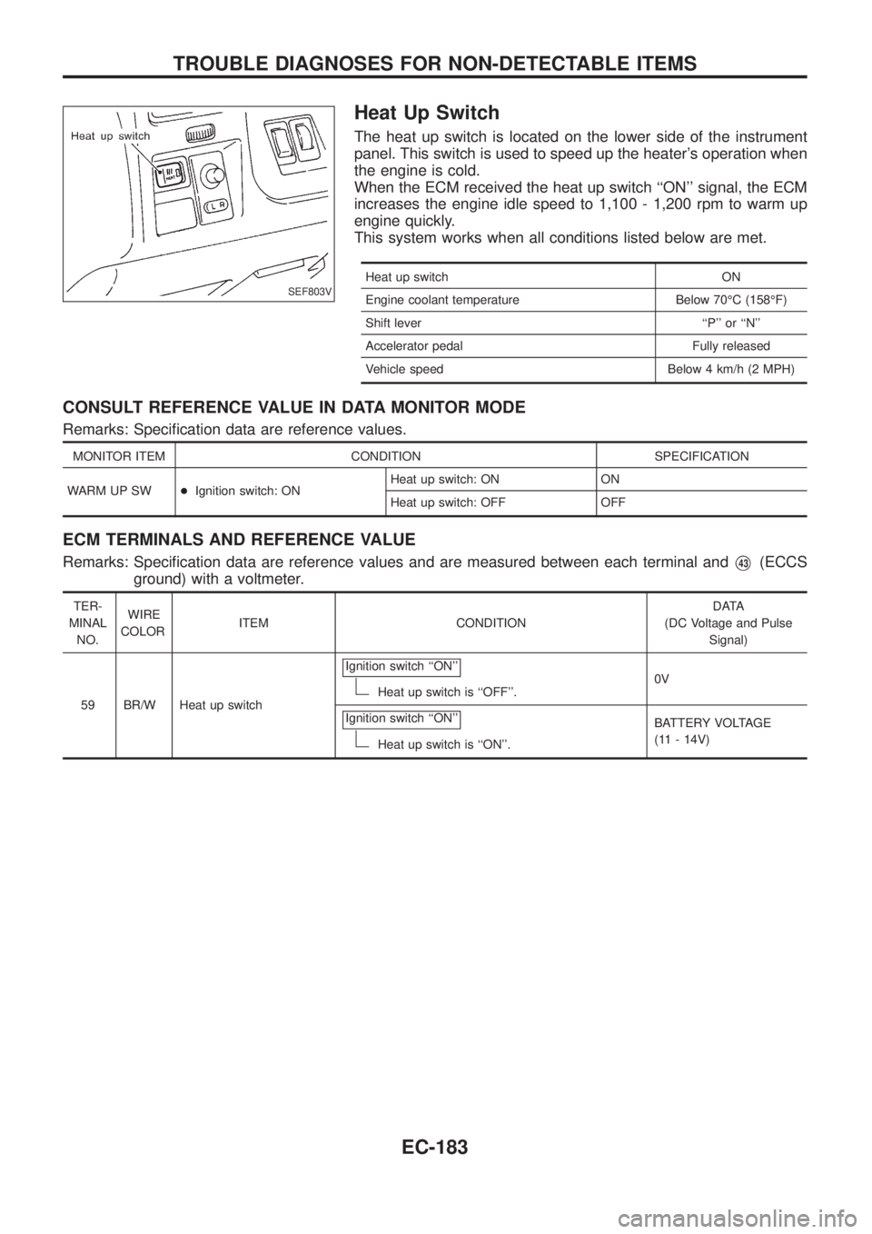
Heat Up Switch
The heat up switch is located on the lower side of the instrument
panel. This switch is used to speed up the heater's operation when
the engine is cold.
When the ECM received the heat up switch ``ON'' signal, the ECM
increases the engine idle speed to 1,100 - 1,200 rpm to warm up
engine quickly.
This system works when all conditions listed below are met.
Heat up switch ON
Engine coolant temperature Below 70ÉC (158ÉF)
Shift lever ``P'' or ``N''
Accelerator pedal Fully released
Vehicle speed Below 4 km/h (2 MPH)
CONSULT REFERENCE VALUE IN DATA MONITOR MODE
Remarks: Speci®cation data are reference values.
MONITOR ITEM CONDITION SPECIFICATION
WARM UP SW+Ignition switch: ONHeat up switch: ON ON
Heat up switch: OFF OFF
ECM TERMINALS AND REFERENCE VALUE
Remarks: Speci®cation data are reference values and are measured between each terminal andV43(ECCS
ground) with a voltmeter.
TER-
MINAL
NO.WIRE
COLORITEM CONDITIONDATA
(DC Voltage and Pulse
Signal)
59 BR/W Heat up switchIgnition switch ``ON''
Heat up switch is ``OFF''.0V
Ignition switch ``ON''
Heat up switch is ``ON''.BATTERY VOLTAGE
(11 - 14V)
SEF803V
TROUBLE DIAGNOSES FOR NON-DETECTABLE ITEMS
EC-183
Page 340 of 1226
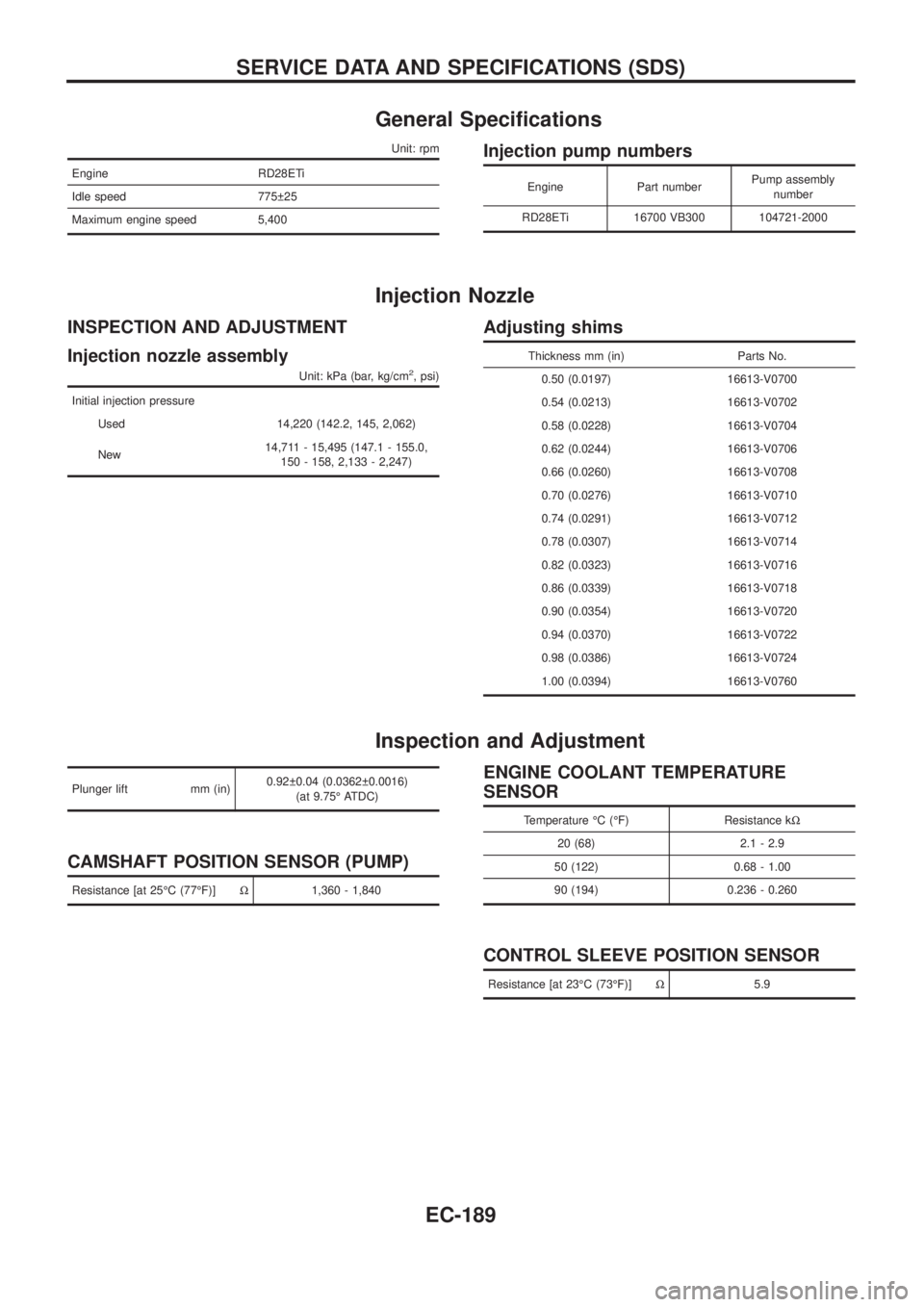
General Speci®cations
Unit: rpm
Engine RD28ETi
Idle speed 775 25
Maximum engine speed 5,400
Injection pump numbers
Engine Part numberPump assembly
number
RD28ETi 16700 VB300 104721-2000
Injection Nozzle
INSPECTION AND ADJUSTMENT
Injection nozzle assembly
Unit: kPa (bar, kg/cm2, psi)
Initial injection pressure
Used 14,220 (142.2, 145, 2,062)
New14,711 - 15,495 (147.1 - 155.0,
150 - 158, 2,133 - 2,247)
Adjusting shims
Thickness mm (in) Parts No.
0.50 (0.0197) 16613-V0700
0.54 (0.0213) 16613-V0702
0.58 (0.0228) 16613-V0704
0.62 (0.0244) 16613-V0706
0.66 (0.0260) 16613-V0708
0.70 (0.0276) 16613-V0710
0.74 (0.0291) 16613-V0712
0.78 (0.0307) 16613-V0714
0.82 (0.0323) 16613-V0716
0.86 (0.0339) 16613-V0718
0.90 (0.0354) 16613-V0720
0.94 (0.0370) 16613-V0722
0.98 (0.0386) 16613-V0724
1.00 (0.0394) 16613-V0760
Inspection and Adjustment
Plunger lift mm (in)0.92 0.04 (0.0362 0.0016)
(at 9.75É ATDC)
CAMSHAFT POSITION SENSOR (PUMP)
Resistance [at 25ÉC (77ÉF)]W1,360 - 1,840
ENGINE COOLANT TEMPERATURE
SENSOR
Temperature ÉC (ÉF) Resistance kW
20 (68) 2.1 - 2.9
50 (122) 0.68 - 1.00
90 (194) 0.236 - 0.260
CONTROL SLEEVE POSITION SENSOR
Resistance [at 23ÉC (73ÉF)]W5.9
SERVICE DATA AND SPECIFICATIONS (SDS)
EC-189
Page 660 of 1226

Use the chart below to ®nd out what each wiring diagram code
stands for.
Code Section Wiring Diagram Name
A/C,A HA Auto Air Conditioner
A/C CUT EC Air Conditioner Cut Control
A/C,M HA Manual Air Conditioner
A/T AT A/T
AAC/V EC IACV-AAC Valve
ABS BR Anti-lock Brake System
ACC/SW EC Accelerator Switch (FC)
ACL/SW EC Accelerator Position Switch
ADJRES EC Adjustment Resistor
APS EC Accelerator Position Sensor
ASCD EL Automatic Speed Control Device
AT/C EC A/T Control
AUDIO EL Audio
BACK/L EL Back-up Lamp
BCDD EC BCDD System
CD/CHG EL CD Auto Changer
CHARGE EL Charging System
CHIME EL Warning Chime
CHOKE EC Automatic Choke
CIGAR EL Cigarette Lighter
CKPS EC Crankshaft Position Sensor (OBD)
CLOCK EL Clock
CMPS EC Camshaft Position Sensor
COMPAS EL Compass and Thermometer
COOL/B HA Cool Box
COOL/F EC Cooling Fan Control
CORNER EL Cornering Lamp
CSPS EC Control Sleeve Position Sensor
D/LOCK EL Power Door Lock
DEICER EL Wiper Deicer
DEF EL Rear Window Defogger
DIFF/L PD Differential Lock Control System
DTRL ELHeadlamp Ð With Daytime Light
System
ECTS EC Engine Coolant Temperature Sensor
EGRC/V EC EGRC-Solenoid Valve
F/FOG EL Front Fog Lamp
F/PUMP EC Fuel Pump
FCUT EC Fuel Cut Solenoid Valve
FICD EC IACV-FICD Solenoid Valve
FTS EC Fuel Temperature SensorCode Section Wiring Diagram Name
GLOW EC Quick Glow System
GOVNR EC Electric Governor
H/AIM EL Headlamp Aiming Control System
H/LAMP EL Headlamp
HEATUP EC Heat up Switch
HLC EL Headlamp Cleaner
HORN EL Horn
HSEAT EL Heated Seat
IATS EC Intake Air Temperature Sensor
IC/FAN EC Charge Air Cooler Fan
IGN EC Ignition System
IGN/SG EC Ignition Signal
ILL EL Illumination
INJECT EC Injector
INT/L EL Spot, Vanity Mirror Lamps
KS EC Knock Sensor
MAFS EC Mass Air Flow Sensor
MAIN ECMain Power Supply and Ground Cir-
cuit
METER ELSpeedometer, Tachometer, Temp.,
Oil and Fuel Gauges
MIL/DL EC Mil and Data Link Connectors
MIRROR EL Door Mirror
MULTI EL Multi-remote Control System
NATS EL Nissan Anti-Theft System
NLS EC Needle Lift Sensor
P/ANT EL Power Antenna
PLA EC Partial Load Advance Control
PNP/SW EC Park/Neutral Position Switch
POWER EL Power Supply Routing
PST/SW EC Power Steering Oil Pressure Switch
R/COOL HA Rear Cooler System
R/FOG EL Rear Fog Lamp
R/HEAT HA Rear Heater System
ROOM/L EL Interior Room Lamp
S/LOCK EL Power Door Lock Ð Super Lock
S/SIG EC Start Signal
S/TANK FE Sub Fuel Tank Control System
SEAT EL Power Seat
SROOF EL Sunroof
SRS RS Supplemental Restraint System
WIRING DIAGRAM CODES (CELL CODES)
EL-315
Page 816 of 1226
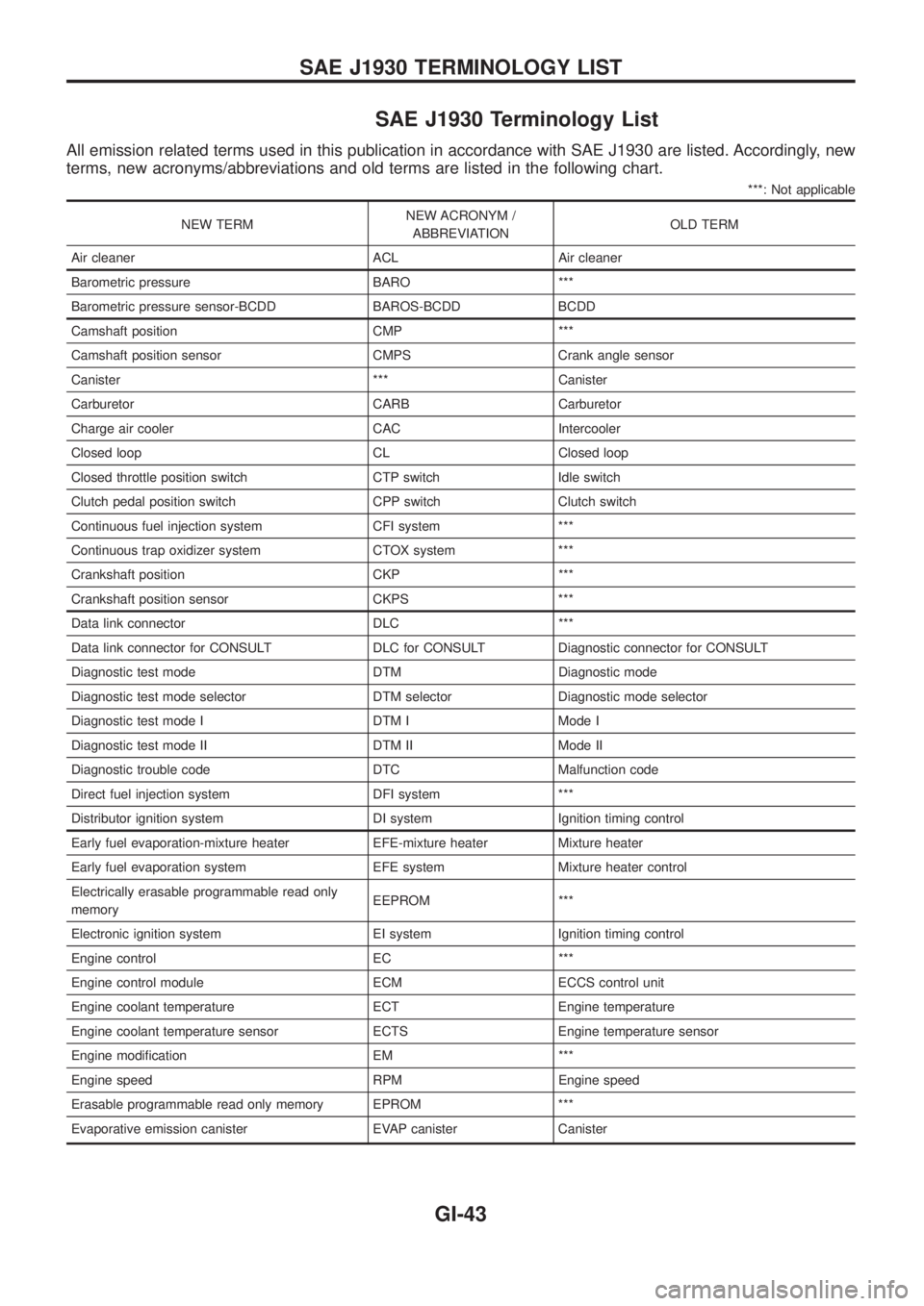
SAE J1930 Terminology List
All emission related terms used in this publication in accordance with SAE J1930 are listed. Accordingly, new
terms, new acronyms/abbreviations and old terms are listed in the following chart.
***: Not applicable
NEW TERMNEW ACRONYM /
ABBREVIATIONOLD TERM
Air cleaner ACL Air cleaner
Barometric pressure BARO ***
Barometric pressure sensor-BCDD BAROS-BCDD BCDD
Camshaft position CMP ***
Camshaft position sensor CMPS Crank angle sensor
Canister *** Canister
Carburetor CARB Carburetor
Charge air cooler CAC Intercooler
Closed loop CL Closed loop
Closed throttle position switch CTP switch Idle switch
Clutch pedal position switch CPP switch Clutch switch
Continuous fuel injection system CFI system ***
Continuous trap oxidizer system CTOX system ***
Crankshaft position CKP ***
Crankshaft position sensor CKPS ***
Data link connector DLC ***
Data link connector for CONSULT DLC for CONSULT Diagnostic connector for CONSULT
Diagnostic test mode DTM Diagnostic mode
Diagnostic test mode selector DTM selector Diagnostic mode selector
Diagnostic test mode I DTM I Mode I
Diagnostic test mode II DTM II Mode II
Diagnostic trouble code DTC Malfunction code
Direct fuel injection system DFI system ***
Distributor ignition system DI system Ignition timing control
Early fuel evaporation-mixture heater EFE-mixture heater Mixture heater
Early fuel evaporation system EFE system Mixture heater control
Electrically erasable programmable read only
memoryEEPROM ***
Electronic ignition system EI system Ignition timing control
Engine control EC ***
Engine control module ECM ECCS control unit
Engine coolant temperature ECT Engine temperature
Engine coolant temperature sensor ECTS Engine temperature sensor
Engine modi®cation EM ***
Engine speed RPM Engine speed
Erasable programmable read only memory EPROM ***
Evaporative emission canister EVAP canister Canister
SAE J1930 TERMINOLOGY LIST
GI-43