2006 NISSAN PATROL oil pressure
[x] Cancel search: oil pressurePage 832 of 1226
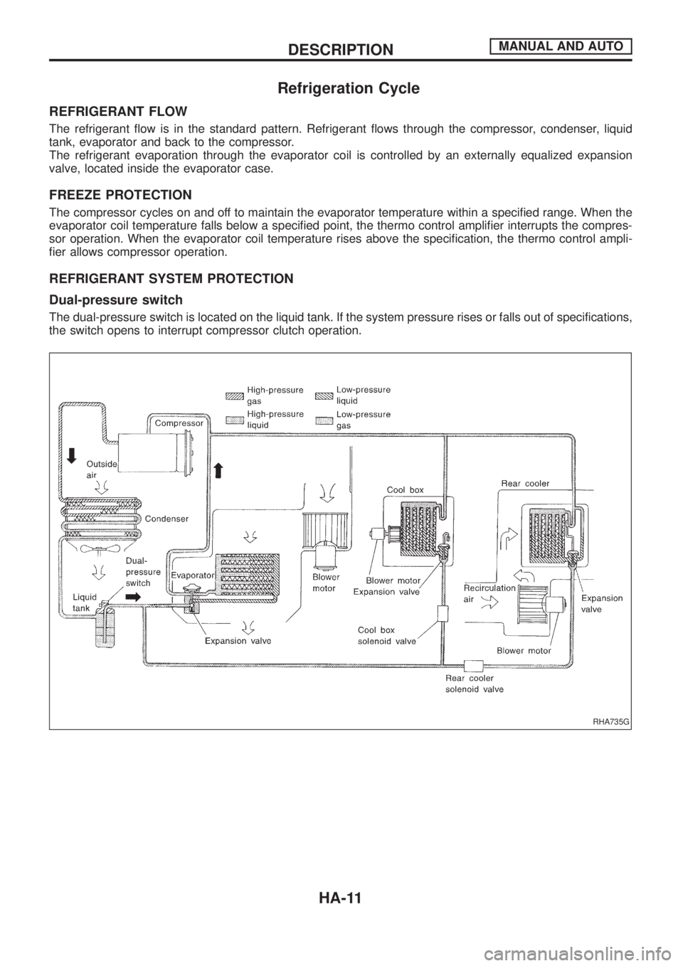
Refrigeration Cycle
REFRIGERANT FLOW
The refrigerant ¯ow is in the standard pattern. Refrigerant ¯ows through the compressor, condenser, liquid
tank, evaporator and back to the compressor.
The refrigerant evaporation through the evaporator coil is controlled by an externally equalized expansion
valve, located inside the evaporator case.
FREEZE PROTECTION
The compressor cycles on and off to maintain the evaporator temperature within a speci®ed range. When the
evaporator coil temperature falls below a speci®ed point, the thermo control ampli®er interrupts the compres-
sor operation. When the evaporator coil temperature rises above the speci®cation, the thermo control ampli-
®er allows compressor operation.
REFRIGERANT SYSTEM PROTECTION
Dual-pressure switch
The dual-pressure switch is located on the liquid tank. If the system pressure rises or falls out of specifications,
the switch opens to interrupt compressor clutch operation.
RHA735G
DESCRIPTIONMANUAL AND AUTO
HA-11
Page 866 of 1226
jA
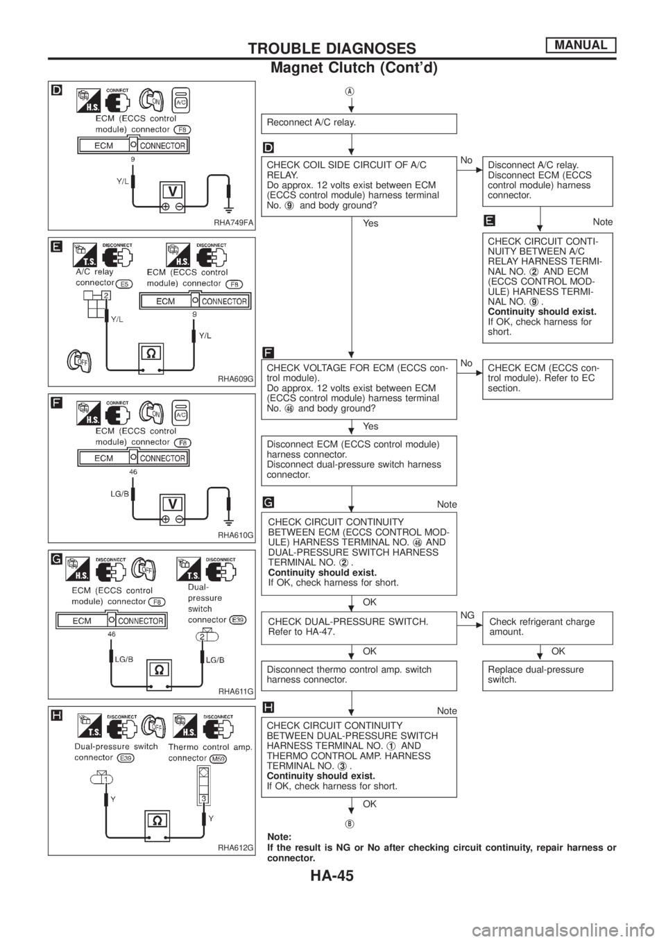
Reconnect A/C relay.
CHECK COIL SIDE CIRCUIT OF A/C
RELAY.
Do approx. 12 volts exist between ECM
(ECCS control module) harness terminal
No.j
9and body ground?
Ye s
cNo
Disconnect A/C relay.
Disconnect ECM (ECCS
control module) harness
connector.
Note
CHECK CIRCUIT CONTI-
NUITY BETWEEN A/C
RELAY HARNESS TERMI-
NAL NO.j
2AND ECM
(ECCS CONTROL MOD-
ULE) HARNESS TERMI-
NAL NO.j
9.
Continuity should exist.
If OK, check harness for
short.
CHECK VOLTAGE FOR ECM (ECCS con-
trol module).
Do approx. 12 volts exist between ECM
(ECCS control module) harness terminal
No.j
46and body ground?
Ye s
cNo
CHECK ECM (ECCS con-
trol module). Refer to EC
section.
Disconnect ECM (ECCS control module)
harness connector.
Disconnect dual-pressure switch harness
connector.
Note
CHECK CIRCUIT CONTINUITY
BETWEEN ECM (ECCS CONTROL MOD-
ULE) HARNESS TERMINAL NO.j
46AND
DUAL-PRESSURE SWITCH HARNESS
TERMINAL NO.j
2.
Continuity should exist.
If OK, check harness for short.
OK
CHECK DUAL-PRESSURE SWITCH.
Refer to HA-47.
OK
cNG
Check refrigerant charge
amount.
OK
Disconnect thermo control amp. switch
harness connector.
Replace dual-pressure
switch.
Note
CHECK CIRCUIT CONTINUITY
BETWEEN DUAL-PRESSURE SWITCH
HARNESS TERMINAL NO.j
1AND
THERMO CONTROL AMP. HARNESS
TERMINAL NO.j
3.
Continuity should exist.
If OK, check harness for short.
OK
j
B
Note:
If the result is NG or No after checking circuit continuity, repair harness or
connector.
RHA749FA
RHA609G
RHA610G
RHA611G
RHA612G
.
.
.
.
.
.
.
..
.
.
TROUBLE DIAGNOSESMANUAL
Magnet Clutch (Cont'd)
HA-45
Page 916 of 1226

jA
Reconnect A/C relay.
CHECK COIL SIDE CIRCUIT OF A/C
RELAY.
Do approx. 12 volts exist between ECM
(ECCS control module) harness terminal
No.j
9and body ground?
Ye s
cNo
Disconnect A/C relay.
Disconnect ECM (ECCS
control module) harness
connector.
Note
CHECK CIRCUIT CONTI-
NUITY BETWEEN A/C
RELAY HARNESS TERMI-
NAL NO.j
2AND ECM
(ECCS CONTROL MOD-
ULE) HARNESS TERMI-
NAL NO.j
9.
Continuity should exist.
If OK, check harness for
short.
CHECK VOLTAGE FOR ECM (ECCS con-
trol module).
Do approx. 12 volts exist between ECM
(ECCS control module) harness terminal
No.j
46and body ground?
Ye s
cNo
CHECK ECM (ECCS con-
trol module). Refer to EC
section.
Disconnect ECM (ECCS control module)
harness connector.
Disconnect dual-pressure switch harness
connector.
Note
CHECK CIRCUIT CONTINUITY
BETWEEN ECM (ECCS CONTROL MOD-
ULE) HARNESS TERMINAL NO.j
46,j21
AND DUAL-PRESSURE SWITCH HAR-
NESS TERMINAL NO.j
2.
Continuity should exist.
If OK, check harness for short.
OK
CHECK DUAL-PRESSURE SWITCH.
Refer to HA-97.
OK
cNG
Replace dual-pressure
switch.
jC
Note:
If the result is NG or No after checking circuit continuity, repair harness
or connector.
RHA655G
RHA656G
RHA657G
RHA658G
.
.
.
.
.
.
.
.
TROUBLE DIAGNOSESAUTO
Magnet Clutch (Cont'd)
HA-95
Page 950 of 1226

Combination meter........................................EL-102
Combination switch .........................................EL-57
Combustion chamber replacement ................EM-32
Compass .......................................................EL-116
Compression pressure ...................................EM-10
Compressor special service tool ......................HA-6
Connecting rod...............................................EM-47
Connecting rod...............................................EM-51
Connector inspection .......................................GI-17
Console box - See Instrument panel ..............BT-11
Control lever (Transfer) .....................................TF-9
Control sleeve position sensor .......................EC-86
Coolant mixture ratio ......................................MA-11
Coolant replacement ......................................MA-14
Cooling circuit (engine) .....................................LC-9
Cooling fan control .......................................EC-112
Cooling fan motor .........................................EC-120
Cooling fan relay ..........................................EC-120
Cooling fan......................................................LC-15
Counter gear (M/T).........................................MT-10
Counter gear (Transfer) ..................................TF-11
Coupling sleeve (M/T) ....................................MT-10
Crankcase emission control system -
See Positive crankcase ventilation.............EC-21
Crankcase ventilation system - See
Positive crankcase ventilation ....................EC-21
Crankshaft position sensor (TDC)................EC-143
Crankshaft ......................................................EM-50
Cylinder block ..........................................EM-45, 48
Cylinder head .................................................EM-28
D
D/LOCK - Wiring diagram .............................EL-205
DEF - Wiring diagram ...................................EL-159
DEICER - Wiring diagram.............................EL-167
DTRL - Wiring diagram ...................................EL-67
Data link connector for Consult......................EC-36
Daytime light system.......................................EL-65
Diagnosis sensor unit .....................................RS-12
Diagnostic trouble code (DTC) for
ECCS OBD system ....................................EC-30
Differential carrier assembly...........................PD-31
Differential carrier disassembly ......................PD-14
Differential gear oil replacement ....................MA-22
Dimensions ......................................................GI-38
Dome light - See Interior lamp .......................EL-93
Door glass .........................................................BT-9
Door lock ...........................................................BT-9
Door mirror ......................................................BT-46
Door trim .........................................................BT-18
Door, front .........................................................BT-9
Door, rear ........................................................BT-10
Drive belt inspection ......................................MA-12
Drive chain (Transfer) .....................................TF-11
Drive pinion diff. inspection ............................PD-19
Drive pinion height .........................................PD-27
Drive shaft (front) ............................................FA-23
Dual pressure switch ......................................HA-11Dual pressure switch ......................................HA-97
E
ECCS basic inspection...................................EC-46
ECCS circuit diagram .....................................EC-11
ECCS component parts location ......................EC-8
ECCS on board diagnostic system ................EC-30
ECCS symptom matrix chart..........................EC-48
ECCS system diagram and chart ..................EC-12
ECCS-D control module .........................EC-54, 110
ECM input/output signal .................................EC-54
ECTS - Wiring diagram ..................................EC-78
EGR control (EGRC) - solenoid valve .........EC-155
EGR control valve ........................................EC-161
EGRC/V - Wiring diagram ............................EC-155
Electric governor ....................................EC-95, 148
Electric sunroof .............................................EL-186
Electrical diagnoses.........................................GI-20
Electrical unit.................................................EL-321
Electrical units location .................................EL-269
Electronic fuel injection pump ........................EC-27
Engine compartment .......................................BT-49
Engine coolant temperature sensor
(ECTS) ........................................................EC-78
Engine oil ®lter replacement ..........................MA-14
Engine oil precautions .......................................GI-4
Engine oil replacement ..................................MA-13
Engine outer component parts ........................EM-8
Engine removal ..............................................EM-43
Engine room - See Engine
compartment ...............................................BT-49
Engine serial number ......................................GI-37
Exhaust system inspection ............................MA-20
Exhaust system ................................................FE-3
Exterior ............................................................BT-26
F
FCUT - Wiring diagram ................................EC-129
FTS - Wiring diagram ...................................EC-134
Fan control amp. ............................................HA-88
Final drive disassembly ..................................PD-14
Final drive removal and installation................PD-11
Finisher, interior - See Trim ............................BT-14
Floor trim .........................................................BT-14
Flow charts ......................................................GI-30
Fluids................................................................MA-9
Flywheel (clutch).......................................CL-13, 14
Flywheel runout..............................................EM-52
Fog lamp, rear ................................................EL-80
Fork rod (M/T) ................................................MT-12
Front axle ........................................................FA-10
Front bumper ....................................................BT-4
Front case (Transfer) ......................................TF-10
Front disc brake .............................................BR-20
Front door .........................................................BT-9
ALPHABETICAL INDEX
IDX-3
Page 952 of 1226
M
M/T major overhaul ..........................................MT-9
M/T removal and installation ............................MT-5
MAFS - Wiring diagram..................................EC-73
MAIN - Wiring diagram...................................EC-62
METER - Wiring diagram..............................EL-104
MIL & Data link connectors circuit ...............EC-187
MIL/DL - Wiring diagram ..............................EC-187
MIRROR - Wiring diagram............................EL-188
Main drive gear (M/T).....................................MT-10
Main gear (Transfer) .......................................TF-11
Mainshaft (M/T) ..............................................MT-10
Mainshaft (Transfer) ........................................TF-11
Maintenance (engine) ....................................MA-12
Major overhaul (Transfer) ...............................TF-10
Malfunction indicator lamp (MIL) ....................EC-31
Manifold tightening torque (intake &
exhaust)......................................................MA-12
Manual lock free running hub .........................FA-11
Manual transmission number ..........................GI-37
Mass air ¯ow sensor (MAFS).........................EC-73
Master cylinder (brake) ..................................BR-12
Meter .............................................................EL-102
Mirror, door......................................................BT-46
Mirror, outside .................................................BT-46
Mode door control linkage adjustment ...........HA-77
Model variation ................................................GI-35
Molding - See Exterior ....................................BT-26
Multiport fuel injection precautions ....................GI-3
N
NATS (Nissan Anti-theft System)..................EL-240
NATS - Wiring diagram .................................EL-241
NLS - Wiring diagram...................................EC-125
NVH Troubleshooting (PD)...............................PD-4
NVH troubleshooting (BR)................................BR-2
NVH troubleshooting (EM) ...............................EM-6
NVH troubleshooting (FA) .................................FA-3
NVH troubleshooting (MT) ...............................MT-3
NVH troubleshooting (RA)................................RA-3
NVH troubleshooting (RA)................................RA-3
NVH troubleshooting (ST).................................ST-3
NVH troubleshooting (Transfer) ........................TF-3
NVH troubleshooting CL ...................................CL-3
Needle lift sensor .........................................EC-125
Neutral position switch (M/T) ...........................MT-4
Neutral position switch .................................EC-169
O
Oil change (capacity) .......................................MA-9
Oil cooler (engine) ............................................LC-7
Oil jet.................................................................LC-7
Oil pan (engine) .............................................EM-13Oil pressure (engine) ........................................LC-3
Oil pump (engine) .............................................LC-4
Oil seal replacement (engine)........................EM-20
Oil seal replacement (front ®nal drive
4WD)...........................................................PD-10
Oil seal replacement (front of ®nal
drive) ...........................................................PD-10
Operating cylinder (clutch)................................CL-8
Outside mirror .................................................BT-46
P
P/ANT - Wiring diagram................................EL-181
PCV (positive crankcase ventilation) .............EC-21
PNP/SW - Wiring diagram ...........................EC-169
POWER - Wiring diagram.................................EL-6
Park/Neutral position switch .........................EC-169
Periodic maintenance (for Europe) ..................MA-4
Pinion bearing preload diff. ............................PD-27
Pinion gear height diff. ...................................PD-27
Piston assembly .............................................EM-46
Piston pin inspection ......................................EM-46
Piston ring inspection.....................................EM-47
Piston to bore clearance ................................EM-48
Power antenna ..............................................EL-181
Power door lock ............................................EL-204
Power door lock ............................................EL-211
Power door mirror .........................................EL-188
Power seat ....................................................EL-190
Power steering ¯uid level..................................ST-5
Power steering gear........................................ST-12
Power steering hydraulic pressure ...................ST-6
Power steering oil pump .................................ST-15
Power steering system bleeding.......................ST-6
Power supply routing ........................................EL-5
Power window ...............................................EL-196
Pre-delivery inspection.....................................MA-2
Precautions (General) .......................................GI-2
Pressure plate - See Clutch cover .................CL-14
Priming pump .................................................EC-46
Propeller shaft greasing .................................MA-21
Propeller shaft inspection ..............................MA-21
Propeller shaft on vehicle service ....................PD-6
Propeller shaft vibration ...................................PD-6
Propeller shaft ..................................................PD-5
Q
Quick-glow system check.............................EC-153
Quick-glow system .......................................EC-150
R
R/FOG - Wiring diagram .................................EL-80
R/HEAT - Wiring diagram ...............................HA-14
ALPHABETICAL INDEX
IDX-5
Page 955 of 1226
ENGINE LUBRICATION &
COOLING SYSTEMS
SECTION
LC
CONTENTS
PRECAUTIONS AND PREPARATION............................1
Liquid Gasket Application Procedure ..........................1
Special Service Tools ..................................................2
ENGINE LUBRICATION SYSTEM..................................3
Lubrication Circuit ........................................................3
Oil Pressure Check......................................................3
Oil Pump ......................................................................4
Oil Cooler .....................................................................7
Oil Jet...........................................................................7
Turbocharger ...............................................................8
ENGINE COOLING SYSTEM..........................................9
Cooling Circuit .............................................................9System Check..............................................................9
Water Pump ...............................................................10
Thermostat .................................................................12
Radiator .....................................................................14
Re®lling Engine Coolant ............................................14
Cooling Fan (Crankshaft driven) ...............................15
Cooling Fan (Motor driven)........................................15
Radiator (Aluminum type) ..........................................16
Overheating Cause Analysis .....................................20
SERVICE DATA AND SPECIFICATIONS (SDS)..........21
Engine Lubrication System ........................................21
Engine Cooling System .............................................21
LC
Page 957 of 1226
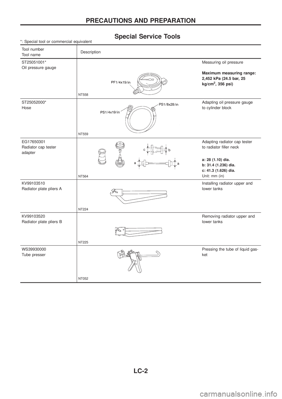
Special Service Tools*: Special tool or commercial equivalent
Tool number
Tool nameDescription
ST25051001*
Oil pressure gauge
NT558
Measuring oil pressure
Maximum measuring range:
2,452 kPa (24.5 bar, 25
kg/cm
2, 356 psi)
ST25052000*
Hose
NT559
Adapting oil pressure gauge
to cylinder block
EG17650301
Radiator cap tester
adapter
NT564
Adapting radiator cap tester
to radiator ®ller neck
a: 28 (1.10) dia.
b: 31.4 (1.236) dia.
c: 41.3 (1.626) dia.
Unit: mm (in)
KV99103510
Radiator plate pliers A
NT224
Installing radiator upper and
lower tanks
KV99103520
Radiator plate pliers B
NT225
Removing radiator upper and
lower tanks
WS39930000
Tube presser
NT052
Pressing the tube of liquid gas-
ket
PRECAUTIONS AND PREPARATION
LC-2
Page 958 of 1226
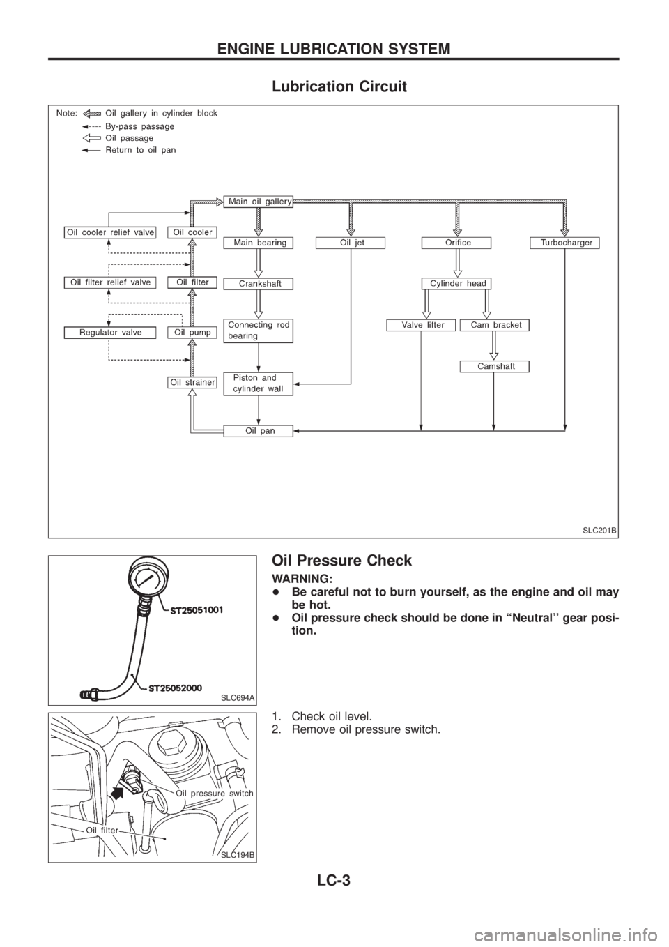
Lubrication Circuit
Oil Pressure Check
WARNING:
+Be careful not to burn yourself, as the engine and oil may
be hot.
+Oil pressure check should be done in ``Neutral'' gear posi-
tion.
1. Check oil level.
2. Remove oil pressure switch.
SLC201B
SLC694A
SLC194B
ENGINE LUBRICATION SYSTEM
LC-3