Page 1068 of 1226

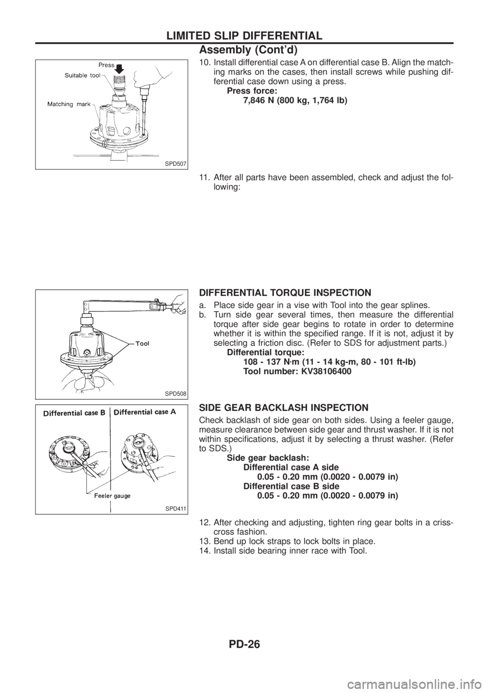
10. Install differential case A on differential case B. Align the match-
ing marks on the cases, then install screws while pushing dif-
ferential case down using a press.
Press force:
7,846 N (800 kg, 1,764 lb)
11. After all parts have been assembled, check and adjust the fol-
lowing:
DIFFERENTIAL TORQUE INSPECTION
a. Place side gear in a vise with Tool into the gear splines.
b. Turn side gear several times, then measure the differential
torque after side gear begins to rotate in order to determine
whether it is within the speci®ed range. If it is not, adjust it by
selecting a friction disc. (Refer to SDS for adjustment parts.)
Differential torque:
108 - 137 Nzm (11 - 14 kg-m, 80 - 101 ft-lb)
Tool number: KV38106400
SIDE GEAR BACKLASH INSPECTION
Check backlash of side gear on both sides. Using a feeler gauge,
measure clearance between side gear and thrust washer. If it is not
within speci®cations, adjust it by selecting a thrust washer. (Refer
to SDS.)
Side gear backlash:
Differential case A side
0.05 - 0.20 mm (0.0020 - 0.0079 in)
Differential case B side
0.05 - 0.20 mm (0.0020 - 0.0079 in)
12. After checking and adjusting, tighten ring gear bolts in a criss-
cross fashion.
13. Bend up lock straps to lock bolts in place.
14. Install side bearing inner race with Tool.
SPD507
SPD508
SPD411
LIMITED SLIP DIFFERENTIAL
Assembly (Cont'd)
PD-26
Page 1073 of 1226
Differential Case Ð 4-pinion type Ð
1. Measure clearance between side gear thrust washer and dif-
ferential case.
Clearance between side gear thrust washer
and differential case (A Ð B):
0.15 - 0.20 mm (0.0059 - 0.0079 in)
The clearance can be adjusted with side gear thrust washer.
Refer to SDS.
2. Apply oil to gear tooth surfaces and thrust surfaces and check
that they turn properly.
3. Install differential case LH and RH.
4. Place differential case on ring gear.
5. Apply locking sealer to ring gear bolts, and install them.
Tighten bolts in a criss-cross fashion, lightly tapping bolt head
with a hammer.
6. Press-®t side bearing inner races on differential case with Tool.
Tool number:
j
AST33190000
j
BST02371000
SPD656
SPD643
SPD746
PD353
ASSEMBLY
PD-31
Page 1074 of 1226
Differential Case Ð 2-pinion type Ð
1. Install side gears, pinion mate gears and thrust washers into
differential case.
2. Fit pinion mate shaft to differential case so that it meets lock pin
holes.
3. Adjust backlash between side gear and pinion mate gear by
selecting side gear thrust washer. Refer to SDS.
Backlash between side gear and pinion mate gear
(Clearance between side gear thrust washer and dif-
ferential case):
0.15 - 0.20 mm (0.0059 - 0.0079 in)
4. Install pinion mate shaft lock pin with a punch.
Make sure lock pin is ¯ush with case.
5. Apply gear oil to gear tooth surfaces and thrust surfaces and
make sure they turn properly.
6. Install differential case assembly on ring gear.
Tighten bolts in a criss-cross pattern, lightly tapping bolt head
with a hammer.
7. Press-®t side bearing inner cones on differential case with Tool.
Tool number:
j
AST33190000
j
BST02371000
SPD552
SPD258
SPD030
SPD322
PD353
ASSEMBLY
PD-32
Page 1078 of 1226
14. Tighten side bearing cap bolts.
15. Install side lock ®nger in place to prevent rotation during opera-
tion.
16. Check runout of ring gear with a dial indicator.
Runout limit: 0.08 mm (0.0031 in)
+If backlash varies excessively in different places, the variance
may have resulted from foreign matter caught between the ring
gear and the differential case.
+If the backlash varies greatly when the runout of the ring gear
is within a speci®ed range, the hypoid gear set or differential
case should be replaced.
17. Check tooth contact. Refer to ADJUSTMENT (PD-27).
SPD698
SPD247
ASSEMBLY
Differential Carrier (Cont'd)
PD-36
Page 1079 of 1226
Actuator and Fork
SPD441A
SPD835-A
DIFFERENTIAL LOCK
PD-37
Page 1080 of 1226
Disassembly
1. Remove side bearing inner cone with Tool. For removal
procedure, refer to ordinary differential case.
2. Loosen ring gear bolts in a criss-cross pattern.
3. Tap ring gear off the gear with a soft hammer.
4. Put marks on both differential cases.
5. Loosen screws on differential cases A and B using a press.
Tool number: ST33081000
6. Separate differential cases A and B.
7. Drive out pinion mate shaft lock pin with Tool.
Draw out component parts.
SPD839
SPD449A
SPD841
DIFFERENTIAL LOCK
PD-38
Page 1081 of 1226
Inspection
CONTACT SURFACES
1. Clean the disassembled parts in suitable solvent and blow dry
with compressed air.
2. If following surfaces are found with burrs or scratches, smooth
with oil stone.
V1Differential case A
V2Differential case B
V3Side gear thrust washer
V4Side gear
V5Pinion mate thrust washer
V6Pinion mate gear
V7Pinion mate shaft
ACTUATOR OPERATION
Apply a vacuum pressure of 66.7 kPa (667 mbar, 500 mmHg, 19.69
inHg) and check its operation and leakage within 10 seconds.
SPD842
SPD906
DIFFERENTIAL LOCK
PD-39
Page 1082 of 1226

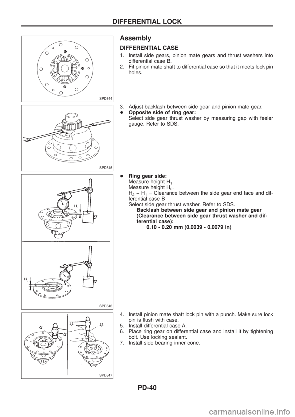
Assembly
DIFFERENTIAL CASE
1. Install side gears, pinion mate gears and thrust washers into
differential case B.
2. Fit pinion mate shaft to differential case so that it meets lock pin
holes.
3. Adjust backlash between side gear and pinion mate gear.
+Opposite side of ring gear:
Select side gear thrust washer by measuring gap with feeler
gauge. Refer to SDS.
+Ring gear side:
Measure height H
1.
Measure height H
2.
H
2þH1= Clearance between the side gear end face and dif-
ferential case B
Select side gear thrust washer. Refer to SDS.
Backlash between side gear and pinion mate gear
(Clearance between side gear thrust washer and dif-
ferential case):
0.10 - 0.20 mm (0.0039 - 0.0079 in)
4. Install pinion mate shaft lock pin with a punch. Make sure lock
pin is ¯ush with case.
5. Install differential case A.
6. Place ring gear on differential case and install it by tightening
bolt. Use locking sealant.
7. Install side bearing inner cone.
SPD844
SPD845
SPD846
SPD847
DIFFERENTIAL LOCK
PD-40