Page 344 of 1226

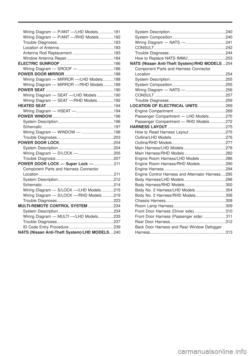
Wiring Diagram Ð P/ANT Ð/LHD Models..............181
Wiring Diagram Ð P/ANT Ð/RHD Models .............182
Trouble Diagnoses...................................................183
Location of Antenna .................................................183
Antenna Rod Replacement .....................................183
Window Antenna Repair ..........................................184
ELECTRIC SUNROOF................................................186
Wiring Diagram Ð SROOF Ð ................................186
POWER DOOR MIRROR............................................188
Wiring Diagram Ð MIRROR Ð/LHD Models..........188
Wiring Diagram Ð MIRROR Ð/RHD Models .........189
POWER SEAT.............................................................190
Wiring Diagram Ð SEAT Ð/LHD Models ...............190
Wiring Diagram Ð SEAT Ð/RHD Models...............192
HEATED SEAT............................................................194
Wiring Diagram Ð HSEAT Ð..................................194
POWER WINDOW.......................................................196
System Description ..................................................196
Schematic ................................................................197
Wiring Diagram Ð WINDOW Ð .............................198
Trouble Diagnoses...................................................203
POWER DOOR LOCK.................................................204
System Description ..................................................204
Wiring Diagram Ð D/LOCK Ð ................................205
Trouble Diagnosis ....................................................207
POWER DOOR LOCK Ð Super Lock Ð.................. 211
Component Parts and Harness Connector
Location ................................................................... 211
System Description ..................................................212
Schematic ................................................................214
Wiring Diagram Ð S/LOCK Ð/LHD Models ...........215
Wiring Diagram Ð S/LOCK Ð/RHD Models ..........219
Trouble Diagnoses...................................................223
MULTI-REMOTE CONTROL SYSTEM.......................234
System Description ..................................................234
Wiring Diagram Ð MULTI Ð/LHD Models..............235
Trouble Diagnoses...................................................237
ID Code Entry Procedure ........................................239
NATS (Nissan Anti-Theft System)/LHD MODELS....240System Description ..................................................240
System Composition ................................................240
Wiring Diagram Ð NATS Ð ....................................241
CONSULT ................................................................242
Trouble Diagnoses...................................................244
How to Replace NATS IMMU ..................................253
NATS (Nissan Anti-Theft System)/RHD MODELS...254
Component Parts and Harness Connector
Location ...................................................................254
System Description ..................................................255
System Composition ................................................255
Wiring Diagram Ð NATS Ð ....................................256
CONSULT ................................................................257
Trouble Diagnoses...................................................259
LOCATION OF ELECTRICAL UNITS.........................269
Engine Compartment ...............................................269
Passenger Compartment Ð LHD Models ...............270
Passenger Compartment Ð RHD Models ..............272
HARNESS LAYOUT....................................................275
How to Read Harness Layout .................................275
Outline/LHD Models.................................................276
Outline/RHD Models ................................................277
Main Harness/LHD Models......................................278
Main Harness/RHD Models .....................................282
Engine Room Harness/LHD Models .......................286
Engine Room Harness/RHD Models .......................290
Engine Harness .......................................................294
Engine Control Harness and Alternator Harness ....295
Body Harness/LHD Models .....................................296
Body Harness/RHD Models.....................................300
Body No. 2 Harness/LHD Models ...........................304
Body No. 2 Harness/RHD Models...........................306
Chassis Harness......................................................308
Room Lamp Harness...............................................309
Front Door Harness (Driver side) ............................310
Front Door Harness (Passenger side) .................... 311
Rear Door Harness..................................................312
Back Door Harness and Rear Window Defogger
Harness....................................................................313
Page 369 of 1226
Back Door and Rear Window Defogger Harness
CEL731
GROUND DISTRIBUTION/LHD MODELS
EL-24
Page 380 of 1226
Back Door and Rear Window Defogger Harness
CEL791
GROUND DISTRIBUTION/RHD MODELS
EL-35
Page 490 of 1226

System Description
WIPER OPERATION
The rear wiper switch is controlled by a ring built into the combination switch.
There are two wiper switch positions:
+ON (LO speed)
+INT (Intermittent)
With the ignition switch in the ON position, power is supplied
+through 10A fuse (No.
18, located in the fuse block)
+to rear wiper motor terminalj
4, and
+to rear wiper ampli®er terminalj
5.
Low speed wiper operation
Ground is supplied to rear wiper switch terminalj24through body grounds.
When the rear wiper is placed in the ON position, ground is supplied
+through rear wiper switch terminalj
22
+to rear wiper relay terminalj6.
Then ground is supplied
+to rear wiper motor terminalj
1
+through rear wiper ampli®er terminalsj2andj3.
With power and ground supplied, the wiper motor operates.
Auto stop operation
With the rear wiper switch turned OFF, rear wiper motor will continue to operate until wiper arm reaches rear
window base.
When wiper arm is not located at base of rear window with rear wiper switch OFF, ground is supplied
+to rear wiper motor terminalj
1
+through rear wiper ampli®er terminalsj2,j7and
+through rear wiper motor terminalj
3, in order to continue rear wiper motor operation at low speed.
Ground is also supplied
+to rear wiper motor terminalj
2
+through body grounds.
When wiper arm reaches base of rear window, rear wiper motor terminalsj
3andj4are connected instead
of terminalsj
2andj3. Rear wiper motor will then stop wiper arm at the PARK position.
Intermittent operation
The rear wiper motor operates the wiper arm one time at low speed at an interval of approximately 7 sec-
onds.
When the rear wiper switch is placed in the INT position, ground is supplied
+to rear wiper ampli®er terminalj
1
+through rear wiper switch terminalj21.
Then the rear wiper motor operates intermittently in the same manner as the low speed wiper operation.
WASHER OPERATION
With the ignition switch in the ACC or ON position, power is supplied
+through 10A fuse (No.
18, located in the fuse block)
+to rear washer motor terminalj
2.
When the ring is turned WASH position, ground is supplied
+to rear washer motor terminalj
1, and
+to rear wiper ampli®er terminalj
4
+through terminalj23of rear wiper switch.
With power and ground is supplied, the rear washer motor operates.
The rear wiper motor operates when the ring is turned to WASH position for one second or more and for
approximately 3 seconds after the ring is released. This feature is controlled by the rear wiper ampli®er in the
same manner as the low speed wiper operation.
REAR WIPER AND WASHER
EL-145
Page 503 of 1226

System Description
The rear window defogger system is controlled by the smart entrance control unit. The rear window defogger
operates only for approximately 15 minutes.
Power is supplied at all times
+to rear window defogger relay terminalj
3
+through 15A fuse (No.43, located in the fuse and fusible link box) and
+to rear window defogger relay terminalj
6
+through 20A fuse (No.44, located in the fuse and fusible link box).
With the ignition switch in the ON or START position, power is supplied
+to the rear window defogger relay terminalj
1and
+to smart entrance control unit terminalj
12
+through 7.5A fuse [No.8, located in the fuse block (J/B)].
Ground is supplied to terminalj
2of the rear window defogger switch through body grounds.
When the rear window defogger switch is turned ON, ground is supplied
+through terminalj
1of the rear window defogger switch
+to smart entrance control unit terminalj
8.
Terminalj
9of the smart entrance control unit then supplies ground to the rear window defogger relay termi-
nalj
2.
With power and ground supplied, the rear window defogger relay is energized.
Power is supplied
+through terminalsj
5andj7of the rear window defogger relay
+to the rear window defogger.
The rear window defogger has an independent ground.
With power and ground supplied, the rear window defogger ®laments heat and defog the rear window.
When the system is activated, the rear window defogger indicator illuminates in the rear window defogger
switch.
Power is supplied
+to terminalj
3of the rear window defogger switch
+from terminalj
5of the rear window defogger relay.
Terminalj
4of the rear window defogger switch is grounded through body grounds.
REAR WINDOW DEFOGGER
EL-158
Page 504 of 1226
Wiring Diagram Ð DEF Ð/LHD Models
TEL449A
REAR WINDOW DEFOGGER
EL-159
Page 505 of 1226
TEL450A
REAR WINDOW DEFOGGER
Wiring Diagram Ð DEF Ð/LHD Models (Cont'd)
EL-160
Page 506 of 1226
Wiring Diagram Ð DEF Ð/RHD Models
TEL657A
REAR WINDOW DEFOGGER
EL-161