2006 NISSAN PATROL oil pressure
[x] Cancel search: oil pressurePage 479 of 1226

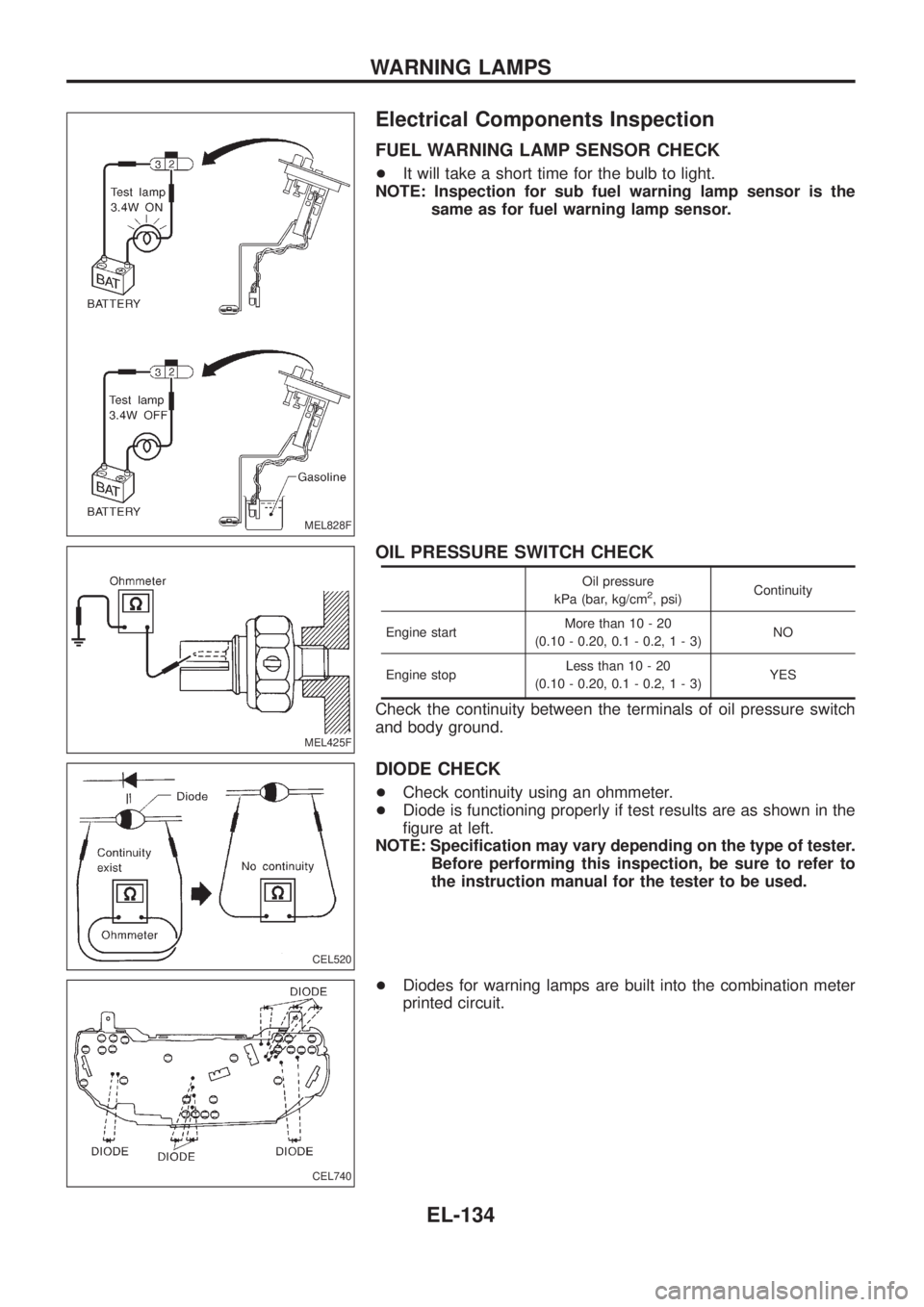
Electrical Components Inspection
FUEL WARNING LAMP SENSOR CHECK
+It will take a short time for the bulb to light.
NOTE: Inspection for sub fuel warning lamp sensor is the
same as for fuel warning lamp sensor.
OIL PRESSURE SWITCH CHECK
Oil pressure
kPa (bar, kg/cm2, psi)Continuity
Engine startMore than 10 - 20
(0.10 - 0.20, 0.1 - 0.2,1-3)NO
Engine stopLess than 10 - 20
(0.10 - 0.20, 0.1 - 0.2,1-3)YES
Check the continuity between the terminals of oil pressure switch
and body ground.
DIODE CHECK
+Check continuity using an ohmmeter.
+Diode is functioning properly if test results are as shown in the
®gure at left.
NOTE: Speci®cation may vary depending on the type of tester.
Before performing this inspection, be sure to refer to
the instruction manual for the tester to be used.
+Diodes for warning lamps are built into the combination meter
printed circuit.
MEL828F
MEL425F
CEL520
CEL740
WARNING LAMPS
EL-134
Page 660 of 1226

Use the chart below to ®nd out what each wiring diagram code
stands for.
Code Section Wiring Diagram Name
A/C,A HA Auto Air Conditioner
A/C CUT EC Air Conditioner Cut Control
A/C,M HA Manual Air Conditioner
A/T AT A/T
AAC/V EC IACV-AAC Valve
ABS BR Anti-lock Brake System
ACC/SW EC Accelerator Switch (FC)
ACL/SW EC Accelerator Position Switch
ADJRES EC Adjustment Resistor
APS EC Accelerator Position Sensor
ASCD EL Automatic Speed Control Device
AT/C EC A/T Control
AUDIO EL Audio
BACK/L EL Back-up Lamp
BCDD EC BCDD System
CD/CHG EL CD Auto Changer
CHARGE EL Charging System
CHIME EL Warning Chime
CHOKE EC Automatic Choke
CIGAR EL Cigarette Lighter
CKPS EC Crankshaft Position Sensor (OBD)
CLOCK EL Clock
CMPS EC Camshaft Position Sensor
COMPAS EL Compass and Thermometer
COOL/B HA Cool Box
COOL/F EC Cooling Fan Control
CORNER EL Cornering Lamp
CSPS EC Control Sleeve Position Sensor
D/LOCK EL Power Door Lock
DEICER EL Wiper Deicer
DEF EL Rear Window Defogger
DIFF/L PD Differential Lock Control System
DTRL ELHeadlamp Ð With Daytime Light
System
ECTS EC Engine Coolant Temperature Sensor
EGRC/V EC EGRC-Solenoid Valve
F/FOG EL Front Fog Lamp
F/PUMP EC Fuel Pump
FCUT EC Fuel Cut Solenoid Valve
FICD EC IACV-FICD Solenoid Valve
FTS EC Fuel Temperature SensorCode Section Wiring Diagram Name
GLOW EC Quick Glow System
GOVNR EC Electric Governor
H/AIM EL Headlamp Aiming Control System
H/LAMP EL Headlamp
HEATUP EC Heat up Switch
HLC EL Headlamp Cleaner
HORN EL Horn
HSEAT EL Heated Seat
IATS EC Intake Air Temperature Sensor
IC/FAN EC Charge Air Cooler Fan
IGN EC Ignition System
IGN/SG EC Ignition Signal
ILL EL Illumination
INJECT EC Injector
INT/L EL Spot, Vanity Mirror Lamps
KS EC Knock Sensor
MAFS EC Mass Air Flow Sensor
MAIN ECMain Power Supply and Ground Cir-
cuit
METER ELSpeedometer, Tachometer, Temp.,
Oil and Fuel Gauges
MIL/DL EC Mil and Data Link Connectors
MIRROR EL Door Mirror
MULTI EL Multi-remote Control System
NATS EL Nissan Anti-Theft System
NLS EC Needle Lift Sensor
P/ANT EL Power Antenna
PLA EC Partial Load Advance Control
PNP/SW EC Park/Neutral Position Switch
POWER EL Power Supply Routing
PST/SW EC Power Steering Oil Pressure Switch
R/COOL HA Rear Cooler System
R/FOG EL Rear Fog Lamp
R/HEAT HA Rear Heater System
ROOM/L EL Interior Room Lamp
S/LOCK EL Power Door Lock Ð Super Lock
S/SIG EC Start Signal
S/TANK FE Sub Fuel Tank Control System
SEAT EL Power Seat
SROOF EL Sunroof
SRS RS Supplemental Restraint System
WIRING DIAGRAM CODES (CELL CODES)
EL-315
Page 668 of 1226

ENGINE MECHANICAL
SECTION
EM
CONTENTS
PRECAUTIONS...............................................................1
Parts Requiring Angular Tightening .............................1
Liquid Gasket Application Procedure ..........................1
PREPARATION................................................................2
NOISE, VIBRATION AND HARSHNESS (NVH)
TROUBLESHOOTING.....................................................6
NVH Troubleshooting Chart Ð Engine Noise .............7
OUTER COMPONENT PARTS.......................................8
COMPRESSION PRESSURE........................................10
Measurement of Compression Pressure ...................10
OIL PAN.........................................................................13
Removal .....................................................................13
Installation ..................................................................14
TIMING BELT.................................................................15
Removal .....................................................................15
Inspection...................................................................17
Installation ..................................................................18
OIL SEAL REPLACEMENT..........................................20
TURBOCHARGER.........................................................23
Removal and Installation ...........................................23
Inspection...................................................................24CHARGE AIR COOLERS..............................................27
CYLINDER HEAD..........................................................28
Removal .....................................................................29
Disassembly...............................................................30
Inspection...................................................................31
Assembly ...................................................................37
Installation ..................................................................37
VALVE CLEARANCE....................................................40
Checking ....................................................................40
Adjusting ....................................................................41
ENGINE REMOVAL.......................................................43
Removal .....................................................................44
Installation ..................................................................44
CYLINDER BLOCK.......................................................45
Disassembly...............................................................46
Inspection...................................................................46
Assembly ...................................................................53
SERVICE DATA AND SPECIFICATIONS (SDS)..........56
General Speci®cations ...............................................56
Inspection and Adjustment ........................................56
EM
Page 680 of 1226

6. Fit compression gauge adapter to cylinder head.
7. Crank engine and read gauge indication.
Crank speed: 200 rpm
Compression pressure:
Standard
3,040 kPa (30.4 bar, 31 kg/cm
2, 441 psi)
Limit
2,452 kPa (24.5 bar, 25 kg/cm
2, 356 psi)
Differential limit between cylinders
490 kPa (4.9 bar, 5 kg/cm
2, 71 psi)
8. If the pressure appears low, pour about 3 m!(0.11 Imp ¯ oz)
of engine oil through nozzle holes and repeat test.
For indications of test, refer to the following table.
Gauge indication during tests Trouble diagnosis
SEM857
+Piston rings are worn or
damaged.
SEM858
+If two adjacent cylinders
are low, gasket is dam-
aged.
+Valve is sticking.
+Valve seat or valve con-
tact surface is incorrected.
9. Replace nozzle gaskets and install injection nozzles.
New nozzle gasket installation direction is as shown.
Nozzle to cylinder head:
:59-69Nzm
(6.0 - 7.0 kg-m, 43 - 51 ft-lb)
SEM706B
SEM708B
COMPRESSION PRESSURE
Measurement of Compression Pressure
(Cont'd)
EM-12
First readingSecond
reading
Increased
reading
Same reading
maintained
Page 725 of 1226

General Speci®cations
Cylinder arrangement In-line 6
Displacement cm
3(cu in) 2,826 (172.44)
Bore and stroke mm (in) 85 x 83 (3.35 x 3.27)
Valve arrangement OHC
Firing order 1-5-3-6-2-4
Number of piston rings
Compression 2
Oil 1
Number of main bearings 7
Compression ratio 21.8
VALVE TIMING
Without warm-up three way catalyst
EM120Unit: degree
abcde f
248 220 7 33 8 60
Inspection and Adjustment
COMPRESSION PRESSURE
Unit: kPa (bar, kg/cm2, psi)/200 rpm
Compression pressure
Standard 3,040 (30.4, 31, 441)
Minimum 2,452 (24.5, 25, 356)
Differential limit between
cylinders490 (4.9, 5, 71)
CYLINDER HEAD
Unit: mm (in)
Standard Limit
Head surface distortionLess than
0.03 (0.0012)0.1 (0.004)
SEM795F
Nominal cylinder head height ``H''139.9 - 140.1
(5.508 - 5.516)
Resurfacing limit 0.1 (0.004)
SERVICE DATA AND SPECIFICATIONS (SDS)
EM-57
Page 776 of 1226

+Clean all disassembled parts in the designated liquid or solvent
prior to inspection or assembly.
+Replace oil seals, gaskets, packings, O-rings, locking washers,
cotter pins, self-locking nuts, etc. with new ones.
+Replace inner and outer races of tapered roller bearings and
needle bearings as a set.
+Arrange the disassembled parts in accordance with their
assembled locations and sequence.
+Do not touch the terminals of electrical components which use
microcomputers (such as ECMs).
Static electricity may damage internal electronic components.
+After disconnecting vacuum or air hoses, attach a tag to indi-
cate the proper connection.
+Use only the ¯uids and lubricants speci®ed in this manual.
+Use approved bonding agent, sealants or their equivalents
when required.
+Use tools and recommended special tools where speci®ed for
safe and efficient service repairs.
+When repairing the fuel, oil, water, vacuum or exhaust systems,
check all affected lines for leaks.
+Dispose of drained oil or the solvent used for cleaning parts in
an appropriate manner.
WARNING:
To prevent ECM from storing the diagnostic trouble codes, do
not carelessly disconnect the harness connectors which are
related to the ECCS system and TCM (Transmission Control
Module) system. The connectors should be disconnected only
when working according to the WORK FLOW of TROUBLE
DIAGNOSES in EC and AT sections.
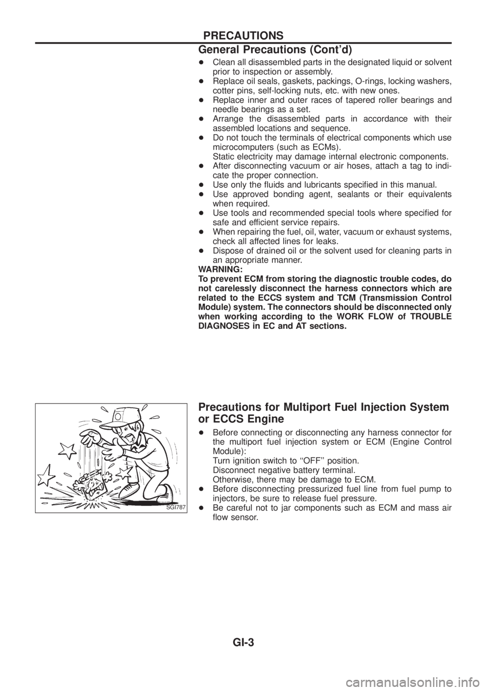
Precautions for Multiport Fuel Injection System
or ECCS Engine
+Before connecting or disconnecting any harness connector for
the multiport fuel injection system or ECM (Engine Control
Module):
Turn ignition switch to ``OFF'' position.
Disconnect negative battery terminal.
Otherwise, there may be damage to ECM.
+
Before disconnecting pressurized fuel line from fuel pump to
injectors, be sure to release fuel pressure.
+Be careful not to jar components such as ECM and mass air
¯ow sensor.SGI787
PRECAUTIONS
General Precautions (Cont'd)
GI-3
Page 826 of 1226

WARNING:
Make sure all refrigerant is discharged into the recycling equipment and the pressure in the system
is less than atmospheric pressure. Then gradually loosen the discharge side hose ®tting and remove
it.
CAUTION:
When replacing or cleaning refrigerant cycle components, observe the following.
+When the compressor is removed, store it in the same position as it is when mounted on the car.
Failure to do so will cause lubricant to enter the low pressure chamber.
+When connecting tubes, always use a torque wrench and a back-up wrench.
+After disconnecting tubes, immediately plug all openings to prevent entry of dirt and moisture.
+When installing an air conditioner in the vehicle, connect the pipes as the ®nal stage of the opera-
tion. Do not remove the seal caps of pipes and other components until just before required for
connection.
+Allow components stored in cool areas to warm to working area temperature before removing seal
caps. This prevents condensation from forming inside A/C components.
+Thoroughly remove moisture from the refrigeration system before charging the refrigerant.
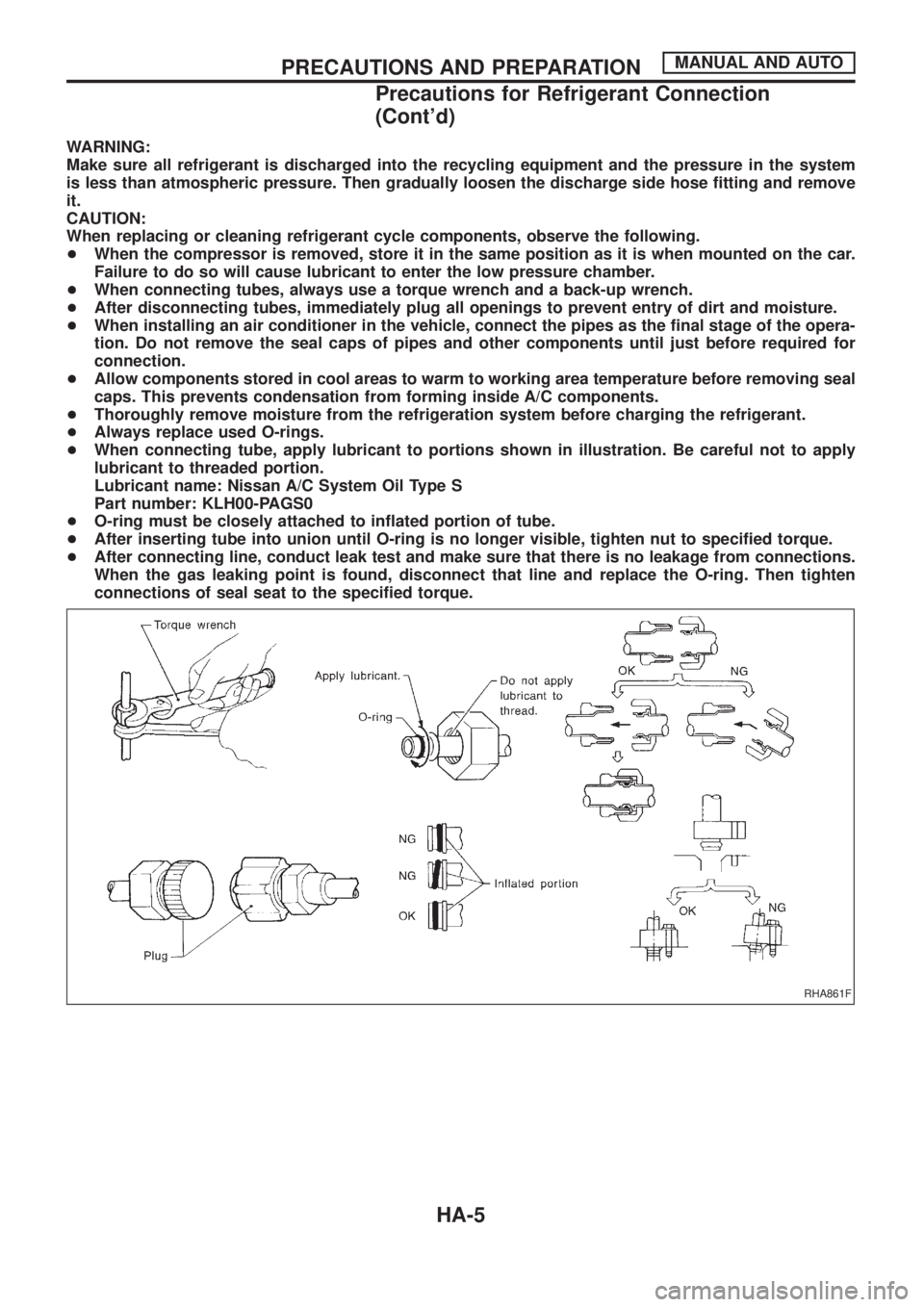
+Always replace used O-rings.
+When connecting tube, apply lubricant to portions shown in illustration. Be careful not to apply
lubricant to threaded portion.
Lubricant name: Nissan A/C System Oil Type S
Part number: KLH00-PAGS0
+O-ring must be closely attached to in¯ated portion of tube.
+After inserting tube into union until O-ring is no longer visible, tighten nut to speci®ed torque.
+After connecting line, conduct leak test and make sure that there is no leakage from connections.
When the gas leaking point is found, disconnect that line and replace the O-ring. Then tighten
connections of seal seat to the speci®ed torque.
RHA861F
PRECAUTIONS AND PREPARATIONMANUAL AND AUTO
Precautions for Refrigerant Connection
(Cont'd)
HA-5
Page 830 of 1226

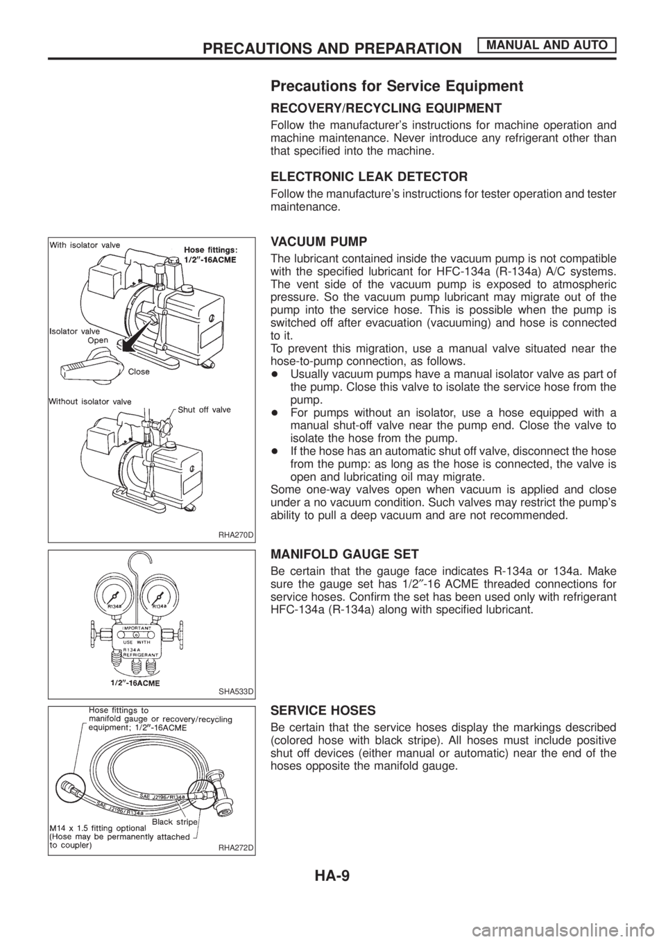
Precautions for Service Equipment
RECOVERY/RECYCLING EQUIPMENT
Follow the manufacturer's instructions for machine operation and
machine maintenance. Never introduce any refrigerant other than
that speci®ed into the machine.
ELECTRONIC LEAK DETECTOR
Follow the manufacture's instructions for tester operation and tester
maintenance.
VACUUM PUMP
The lubricant contained inside the vacuum pump is not compatible
with the speci®ed lubricant for HFC-134a (R-134a) A/C systems.
The vent side of the vacuum pump is exposed to atmospheric
pressure. So the vacuum pump lubricant may migrate out of the
pump into the service hose. This is possible when the pump is
switched off after evacuation (vacuuming) and hose is connected
to it.
To prevent this migration, use a manual valve situated near the
hose-to-pump connection, as follows.
+Usually vacuum pumps have a manual isolator valve as part of
the pump. Close this valve to isolate the service hose from the
pump.
+For pumps without an isolator, use a hose equipped with a
manual shut-off valve near the pump end. Close the valve to
isolate the hose from the pump.
+If the hose has an automatic shut off valve, disconnect the hose
from the pump: as long as the hose is connected, the valve is
open and lubricating oil may migrate.
Some one-way valves open when vacuum is applied and close
under a no vacuum condition. Such valves may restrict the pump's
ability to pull a deep vacuum and are not recommended.
MANIFOLD GAUGE SET
Be certain that the gauge face indicates R-134a or 134a. Make
sure the gauge set has 1/2²-16 ACME threaded connections for
service hoses. Con®rm the set has been used only with refrigerant
HFC-134a (R-134a) along with speci®ed lubricant.
SERVICE HOSES
Be certain that the service hoses display the markings described
(colored hose with black stripe). All hoses must include positive
shut off devices (either manual or automatic) near the end of the
hoses opposite the manifold gauge.
RHA270D
SHA533D
RHA272D
PRECAUTIONS AND PREPARATIONMANUAL AND AUTO
HA-9