Page 1039 of 1226
General Speci®cations
Applied modelRD28ETi
4WD
Transmission FS5R30A
Number of speed 5
Transmission control Floor direct
Shift pattern
Synchromesh type Warner
Gear ratio
1st 4.061
2nd 2.357
3rd 1.490
4th 1.000
OD 0.862
Reverse 4.125
Number of teeth
Mainshaft
Drive 20
1st 32
2nd 30
3rd 28
OD 23
Reverse 30
Countershaft
Drive 33
1st 13
2nd 21
3rd 31
OD 44
Reverse 12
Reverse idler gear 22
Oil capacity!(Imp pt) 5.1 (9)
Remarks2nd & 3rd double baulk ring
type synchronizer
Reverse breaking mechanism type
SERVICE DATA AND SPECIFICATIONS (SDS)
MT-32
Page 1085 of 1226
System Description
The differential lock operates only in 4WD.
The differential lock control unit interrupts current ¯owing through
differential lock solenoid-2 when vehicle speed exceeds 7 km/h (4
MPH). If the differential lock switch is accidentally turned on when
vehicle speed is greater than 7 km/h (4 MPH), the control unit will
prevent the differential lock from sustaining impact damage.
A warning buzzer will sound when the vehicle is driven over 20
km/h (12 MPH) with the differential lock engaged.
SPD446A
DIFFERENTIAL LOCK
PD-43
Page 1092 of 1226

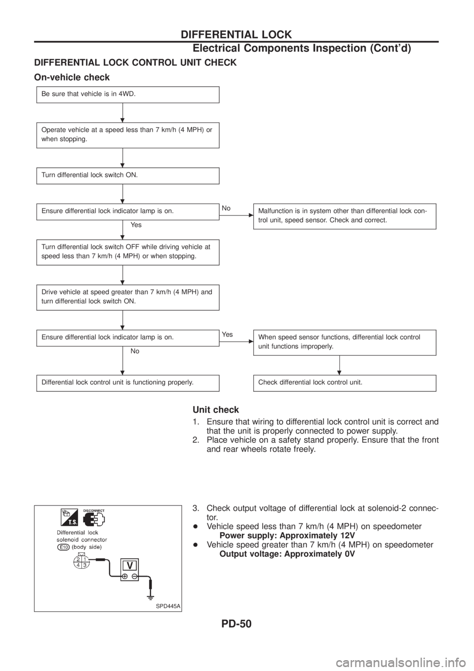
DIFFERENTIAL LOCK CONTROL UNIT CHECK
On-vehicle check
Be sure that vehicle is in 4WD.
Operate vehicle at a speed less than 7 km/h (4 MPH) or
when stopping.
Turn differential lock switch ON.
Ensure differential lock indicator lamp is on.
Ye s
cNo
Malfunction is in system other than differential lock con-
trol unit, speed sensor. Check and correct.
Turn differential lock switch OFF while driving vehicle at
speed less than 7 km/h (4 MPH) or when stopping.
Drive vehicle at speed greater than 7 km/h (4 MPH) and
turn differential lock switch ON.
Ensure differential lock indicator lamp is on.
No
cYe s
When speed sensor functions, differential lock control
unit functions improperly.
Differential lock control unit is functioning properly.Check differential lock control unit.
Unit check
1. Ensure that wiring to differential lock control unit is correct and
that the unit is properly connected to power supply.
2. Place vehicle on a safety stand properly. Ensure that the front
and rear wheels rotate freely.
3. Check output voltage of differential lock at solenoid-2 connec-
tor.
+Vehicle speed less than 7 km/h (4 MPH) on speedometer
Power supply: Approximately 12V
+Vehicle speed greater than 7 km/h (4 MPH) on speedometer
Output voltage: Approximately 0V
SPD445A
.
.
.
.
.
.
..
DIFFERENTIAL LOCK
Electrical Components Inspection (Cont'd)
PD-50
Page 1200 of 1226
Checking Position Switch
4WD SWITCH
Transfer control lever position Continuity
4H, 4L Yes
Except above No
NEUTRAL POSITION SWITCH
Transfer control lever position Continuity
Between 4H and 4L
(``PUSH'' position)Ye s
Except above No
SMT252D
SMT253D
ON-VEHICLE SERVICE
TF-7
Page 1201 of 1226
Removal
1. Drain ¯uid and oil from transfer and transmission (M/T model
only).
2. Remove exhaust front and rear tubes. Refer to FE section
(``EXHAUST SYSTEM'').
3. Remove front and rear propeller shaft. Refer to PD section
(``Removal and Installation'', ``PROPELLER SHAFT'').
4. Disconnect neutral position switch and 4WD switch harness
connectors.
5. Remove transfer control lever from transfer cross shaft.
6. Remove transfer from transmission.
WARNING:
Support transfer while removing it.
Installation
+Apply recommended sealant to mating surface to transmission.
(M/T models only)
Recommended sealant:
Genuine anaerobic liquid gasket, Three Bond
TB1215, Loctite Part No. 51813 or equivalent
+Tighten transfer bolts.
Transfer ®xing bolts:
:32-42Nzm (3.3 - 4.3 kg-m, 24 - 31 ft-lb)
SMT251D
SMT268D
SMT176BA
REMOVAL AND INSTALLATION
TF-8
Page 1210 of 1226
16. Disassemble front case assembly.
a. Remove the following parts.
+4WD switch
+Neutral position switch
+Check plugs
+Check springs
+Check balls
+Be careful not to lose the check balls.
b. Remove 2-4 shift rod.
c. Remove L & H shift rod and fork assembly with coupling sleeve.
d. Remove needle bearing from main gear.
e. Remove bolts securing front case cover and then remove it.
SMT259D
SMT122B
SMT260D
SMT124B
SMT125B
DISASSEMBLY
TF-17