Page 279 of 341
Contact a NISSAN dealer if checking or replace-
ment is required.
CHECKING PARKING BRAKEFrom the released position, depress the parking
brake pedal slowly and firmly, and check the
notches between the initial and final positions of
the pedal. If it is out of the range shown above,
see a NISSAN dealer.
CHECKING BRAKE PEDALWith the engine running, check the distance
between the upper surface of the pedal and the
metal floor. If it is out of the range shown above,
see a NISSAN dealer.
Adjustable pedal equipped model:
The pedal must be in the front most position
when checking.Self-adjusting brakesYour vehicle is equipped with self-adjusting
brakes.
SDI1391C
DI1020MQ
REAR WINDOW WIPER BLADE
PARKING BRAKE AND BRAKE
PEDAL8-20
Maintenance and do-it-yourself
�
05.8.26/Z50-D/V5.0
�
Page 280 of 341

The disc-type brakes self-adjust every time the
brake pedal is applied.
WARNING
See a NISSAN dealer and have it
checked if the brake pedal height does
not return to normal.Brake pad wear indicatorsThe disc brake pads on your vehicle have au-
dible wear indicators. When a brake pad re-
quires replacement, it will make a high pitched
scraping or screeching sound when the vehicle
is in motion whether or not the brake pedal is
depressed. Have the brakes checked as soon as
possible if the wear indicator sound is heard.
Under some driving or climate conditions, occa-
sional brake squeak, squeal or other noise may
be heard. Occasional brake noise during light to
moderate stops is normal and does not affect
the function or performance of the brake system.
Proper brake inspection intervals should
be followed.For additional information, see the
separate Service and Maintenance Guide.
BRAKE BOOSTERCheck the brake booster function as follows:
1. With the engine off, depress and release the
brake pedal several times. When brake pedal
movement (distance of travel) remains the
same from one pedal application to the next,
continue on to the next step.
2. While depressing the brake pedal, start the
engine. The pedal height should drop a little.
3. With the brake pedal depressed, stop the
engine. Keeping the pedal depressed for
about 30 seconds, the pedal height should
not change.
4. Run the engine for one minute without de-
pressing the brake pedal, then turn it off.
Depress the brake pedal several times. The
pedal travel distance will decrease gradually
with each depression as the vacuum is re-
leased from the booster.
If the brakes do not operate properly, see a
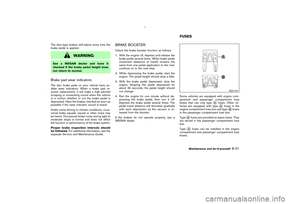
NISSAN dealer.Some vehicles are equipped with engine com-
partment and passenger compartment fuse
boxes that use only type
�A
fuses. Other ve-
hicles are equipped with type�A
fuses in the
engine compartment fuse box and type
�Bfuses
in the passenger compartment fuse box.
Type
�Afuses are provided as spare fuses. They
are stored in the passenger compartment fuse
box.
Type
�A
fuses can be installed in the engine
compartment and passenger compartment fuse
boxes.
SDI1751
FUSES
Maintenance and do-it-yourself
8-21
�
05.8.26/Z50-D/V5.0
�
Page 281 of 341

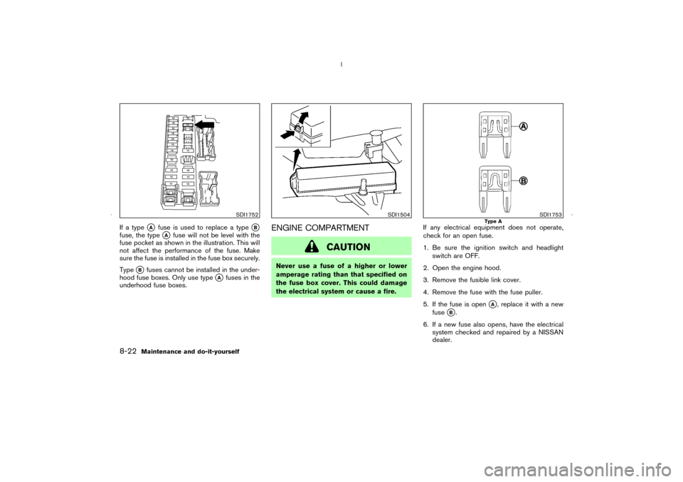
If a type
�A
fuse is used to replace a type
�B
fuse, the type
�A
fuse will not be level with the
fuse pocket as shown in the illustration. This will
not affect the performance of the fuse. Make
sure the fuse is installed in the fuse box securely.
Type
�B
fuses cannot be installed in the under-
hood fuse boxes. Only use type
�A
fuses in the
underhood fuse boxes.
ENGINE COMPARTMENT
CAUTION
Never use a fuse of a higher or lower
amperage rating than that specified on
the fuse box cover. This could damage
the electrical system or cause a fire.If any electrical equipment does not operate,
check for an open fuse.
1. Be sure the ignition switch and headlight
switch are OFF.
2. Open the engine hood.
3. Remove the fusible link cover.
4. Remove the fuse with the fuse puller.
5. If the fuse is open
�A, replace it with a new
fuse
�B.
6. If a new fuse also opens, have the electrical
system checked and repaired by a NISSAN
dealer.
SDI1752
SDI1504
SDI1753
Type A
8-22
Maintenance and do-it-yourself
�
05.8.26/Z50-D/V5.0
�
Page 282 of 341
Fusible linksIf any electrical equipment does not operate and
fuses are in good condition, check the fusible
links. If any of these fusible links are melted,
replace only with genuine NISSAN parts.
PASSENGER COMPARTMENT
CAUTION
Never use a fuse of a higher or lower
amperage rating than that specified on
the fuse box cover. This could damage
the electrical system or cause a fire.
If any electrical equipment does not operate,
check for an open fuse.
1. Be sure the ignition switch and the headlight
switch are OFF.2. Pull to open the fuse box lid
�1.
3. Pinch the fuse perpendicularly with the fuse
puller
�A
and pull it out.
4. If the fuse is open, replace it with a new fuse
�B.
5. If a new fuse also opens, have the electrical
system checked and repaired by a NISSAN
dealer.
SDI1754
Type B
SDI1505
Maintenance and do-it-yourself
8-23
�
05.8.26/Z50-D/V5.0
�
Page 283 of 341

KEYFOBReplace the battery as follows:
1. Open the lid using a suitable tool.
2. Replace the battery with a new one.Recommended battery: Sanyo CR2025 or
equivalent
Make sure that the
⊕
side faces the
bottom case.
3. Close the lid securely.
4. Push the keyfobbutton two or three times to
check its operation.
See a NISSAN dealer if you need any assistance
for replacement.
If the battery is removed for any reason
other than replacement, perform step 4
above.
�Be careful not to touch a circuit board
and a battery terminal.
�An improperly disposed battery can
harm the environment. Always confirm
local regulations for battery disposal.
�The keyfob is water-resistant; however,
if it does get wet, immediately wipe
completely dry.
�When changing batteries, do not let
dust or oil get on the keyfob.
FCC Notice:
Changes or modifications not expressly
approved by the party responsible for com-pliance could void the user’s authority to
operate the equipment. This device com-
plies with Part 15 of the FCC Rules and
RSS-210 of Industry Canada. Operation is
subject to the following two conditions: (1)
This device may not cause harmful interfer-
ence, and (2) this device must accept any
interference received, including interfer-
ence that may cause undesired operation
of the device.
SPA1374
BATTERY REPLACEMENT8-24
Maintenance and do-it-yourself
�
05.8.26/Z50-D/V5.0
�
Page 284 of 341

INTELLIGENT KEY
CAUTION
Be careful not to allow children to swal-
low the battery and removed parts.
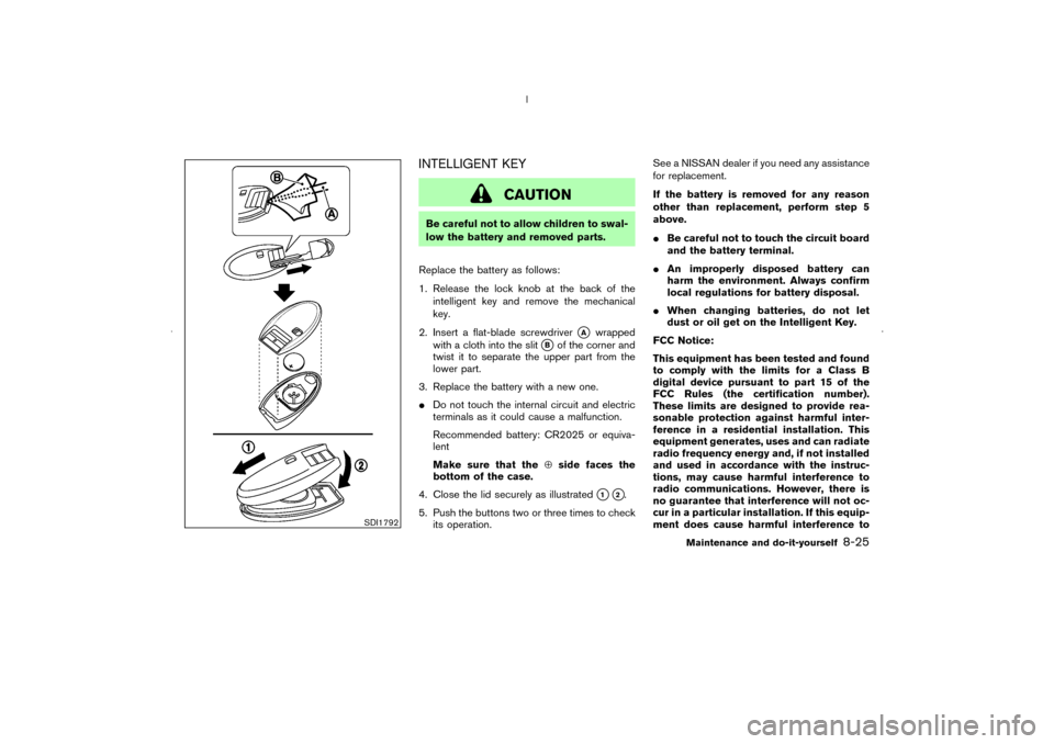
Replace the battery as follows:
1. Release the lock knobat the back of the
intelligent key and remove the mechanical
key.
2. Insert a flat-blade screwdriver
�A
wrapped
with a cloth into the slit
�B
of the corner and
twist it to separate the upper part from the
lower part.
3. Replace the battery with a new one.
�Do not touch the internal circuit and electric
terminals as it could cause a malfunction.
Recommended battery: CR2025 or equiva-
lent
Make sure that the⊕side faces the
bottom of the case.
4. Close the lid securely as illustrated
�1�2.
5. Push the buttons two or three times to check
its operation.See a NISSAN dealer if you need any assistance
for replacement.
If the battery is removed for any reason
other than replacement, perform step 5
above.
�Be careful not to touch the circuit board
and the battery terminal.
�An improperly disposed battery can
harm the environment. Always confirm
local regulations for battery disposal.
�When changing batteries, do not let
dust or oil get on the Intelligent Key.
FCC Notice:
This equipment has been tested and found
to comply with the limits for a Class B
digital device pursuant to part 15 of the
FCC Rules (the certification number).
These limits are designed to provide rea-
sonable protection against harmful inter-
ference in a residential installation. This
equipment generates, uses and can radiate
radio frequency energy and, if not installed
and used in accordance with the instruc-
tions, may cause harmful interference to
radio communications. However, there is
no guarantee that interference will not oc-
cur in a particular installation. If this equip-
ment does cause harmful interference to
SDI1792
Maintenance and do-it-yourself
8-25
�
05.8.26/Z50-D/V5.0
�
Page 285 of 341
radio or television reception, which can be
determined by turning the equipment off
and on, the user is encouraged to try to
correct the interference by one or more of
the following measures:
— Reorient or relocate the receiving an-
tenna
— Increase the separation between the
equipment and the receiver
— Connect the equipment into an outlet on
a circuit different from that to which the
receiver is connected.
— Consult the dealer or an experienced
radio/TV technician for help.8-26
Maintenance and do-it-yourself
�
05.8.26/Z50-D/V5.0
�
Page 286 of 341
1. Front turn signal light or front park light
2. Headlight (low-beam, high-beam)
3. Front park light or front turn signal light
4. Map light
5. Ceiling light
6. Rear personal light
7. Front fog light (if so equipped)/Daytime, run-
ning light (for Canada)
8. Front side marker light
9. Step light
10. High-mounted stop light
11. Rear combination light
— Turn signal/Stop/Tail light
— Side marker light
12. License plate lights
13. Back-up light
14. Luggage light
SDI1960
LIGHTS
Maintenance and do-it-yourself
8-27
�
05.8.26/Z50-D/V5.0
�