2006 NISSAN FRONTIER clock
[x] Cancel search: clockPage 223 of 336
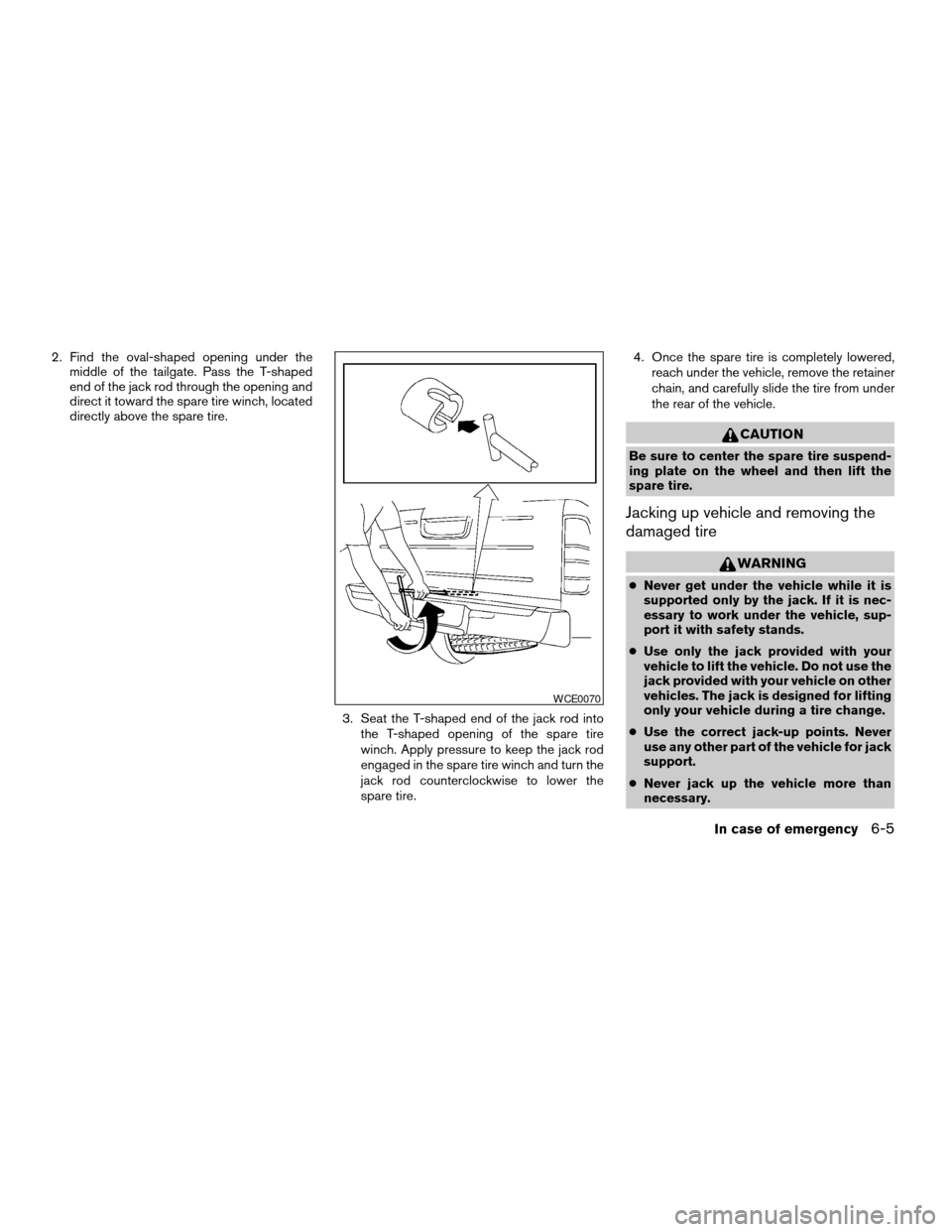
2. Find the oval-shaped opening under the
middle of the tailgate. Pass the T-shaped
end of the jack rod through the opening and
direct it toward the spare tire winch, located
directly above the spare tire.
3. Seat the T-shaped end of the jack rod into
the T-shaped opening of the spare tire
winch. Apply pressure to keep the jack rod
engaged in the spare tire winch and turn the
jack rod counterclockwise to lower the
spare tire.4. Once the spare tire is completely lowered,
reach under the vehicle, remove the retainer
chain, and carefully slide the tire from under
the rear of the vehicle.
CAUTION
Be sure to center the spare tire suspend-
ing plate on the wheel and then lift the
spare tire.
Jacking up vehicle and removing the
damaged tire
WARNING
cNever get under the vehicle while it is
supported only by the jack. If it is nec-
essary to work under the vehicle, sup-
port it with safety stands.
cUse only the jack provided with your
vehicle to lift the vehicle. Do not use the
jack provided with your vehicle on other
vehicles. The jack is designed for lifting
only your vehicle during a tire change.
cUse the correct jack-up points. Never
use any other part of the vehicle for jack
support.
cNever jack up the vehicle more than
necessary.
WCE0070
In case of emergency6-5
ZREVIEW COPYÐ2006 Truck/Frontier(d22)
Owners ManualÐUSA_English(nna)
10/17/05Ðdebbie
X
Page 224 of 336
cNever use blocks on or under the jack.
cDo not start or run the engine while
vehicle is on the jack. It may cause the
vehicle to move. This is especially true
for vehicles with limited slip
differentials.
cDo not allow passengers to stay in the
vehicle while it is on the jack.
cNever run the engine with a wheel(s) off
the ground. It may cause the vehicle to
move.
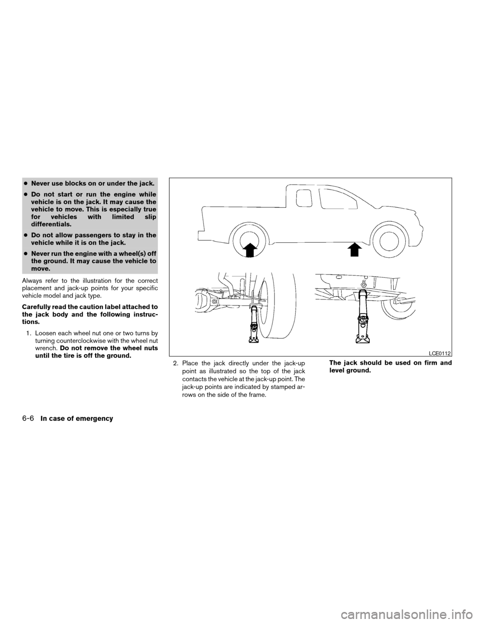
Always refer to the illustration for the correct
placement and jack-up points for your specific
vehicle model and jack type.
Carefully read the caution label attached to
the jack body and the following instruc-
tions.
1. Loosen each wheel nut one or two turns by
turning counterclockwise with the wheel nut
wrench.Do not remove the wheel nuts
until the tire is off the ground.
2. Place the jack directly under the jack-up
point as illustrated so the top of the jack
contacts the vehicle at the jack-up point. The
jack-up points are indicated by stamped ar-
rows on the side of the frame.The jack should be used on firm and
level ground.
LCE0112
6-6In case of emergency
ZREVIEW COPYÐ2006 Truck/Frontier(d22)
Owners ManualÐUSA_English(nna)
10/17/05Ðdebbie
X
Page 250 of 336
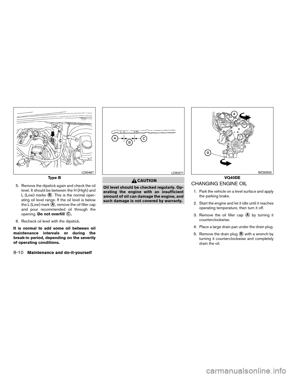
5. Remove the dipstick again and check the oil
level. It should be between the H (High) and
L (Low) marks
sB. This is the normal oper-
ating oil level range. If the oil level is below
the L (Low) mark
sA, remove the oil filler cap
and pour recommended oil through the
opening.Do not overfill
sC.
6. Recheck oil level with the dipstick.
It is normal to add some oil between oil
maintenance intervals or during the
break-in period, depending on the severity
of operating conditions.
CAUTION
Oil level should be checked regularly. Op-
erating the engine with an insufficient
amount of oil can damage the engine, and
such damage is not covered by warranty.CHANGING ENGINE OIL
1. Park the vehicle on a level surface and apply
the parking brake.
2. Start the engine and let it idle until it reaches
operating temperature, then turn it off.
3. Remove the oil filler cap
sAby turning it
counterclockwise.
4. Place a large drain pan under the drain plug.
5. Remove the drain plug
sBwith a wrench by
turning it counterclockwise and completely
drain the oil.
Type B
LDI0467LDI0371
VQ40DE
WDI0500
8-10Maintenance and do-it-yourself
ZREVIEW COPYÐ2006 Truck/Frontier(d22)
Owners ManualÐUSA_English(nna)
10/17/05Ðdebbie
X
Page 252 of 336
CHANGING ENGINE OIL FILTER
1. Park the vehicle on a level surface and apply
the parking brake.
2. Turn the engine off.
3. Place a large drain pan under the oil filter.
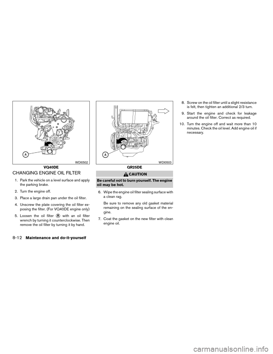
4. Unscrew the plate covering the oil filter ex-
posing the filter. (For VQ40DE engine only)
5. Loosen the oil filter
sAwith an oil filter
wrench by turning it counterclockwise. Then
remove the oil filter by turning it by hand.
CAUTION
Be careful not to burn yourself. The engine
oil may be hot.
6. Wipe the engine oil filter sealing surface with
a clean rag.
Be sure to remove any old gasket material
remaining on the sealing surface of the en-
gine.
7. Coat the gasket on the new filter with clean
engine oil.8. Screw on the oil filter until a slight resistance
is felt, then tighten an additional 2/3 turn.
9. Start the engine and check for leakage
around the oil filter. Correct as required.
10. Turn the engine off and wait more than 10
minutes. Check the oil level. Add engine oil if
necessary.
VQ40DE
WDI0502
QR25DE
WDI0503
8-12Maintenance and do-it-yourself
ZREVIEW COPYÐ2006 Truck/Frontier(d22)
Owners ManualÐUSA_English(nna)
10/17/05Ðdebbie
X
Page 269 of 336
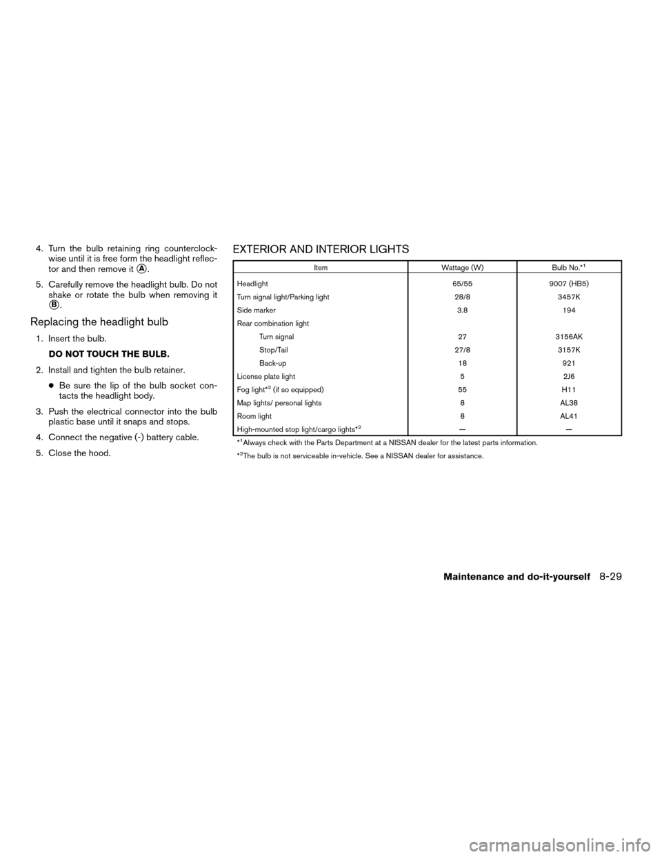
4. Turn the bulb retaining ring counterclock-
wise until it is free form the headlight reflec-
tor and then remove it
sA.
5. Carefully remove the headlight bulb. Do not
shake or rotate the bulb when removing it
sB.
Replacing the headlight bulb
1. Insert the bulb.
DO NOT TOUCH THE BULB.
2. Install and tighten the bulb retainer.
cBe sure the lip of the bulb socket con-
tacts the headlight body.
3. Push the electrical connector into the bulb
plastic base until it snaps and stops.
4. Connect the negative (-) battery cable.
5. Close the hood.
EXTERIOR AND INTERIOR LIGHTS
Item Wattage (W) Bulb No.*1
Headlight 65/55 9007 (HB5)
Turn signal light/Parking light 28/8 3457K
Side marker 3.8 194
Rear combination light
Turn signal 27 3156AK
Stop/Tail 27/8 3157K
Back-up 18 921
License plate light 5 2J6
Fog light*
2(if so equipped) 55 H11
Map lights/ personal lights 8 AL38
Room light 8 AL41
High-mounted stop light/cargo lights*
2——
*1Always check with the Parts Department at a NISSAN dealer for the latest parts information.
*2The bulb is not serviceable in-vehicle. See a NISSAN dealer for assistance.
Maintenance and do-it-yourself8-29
ZREVIEW COPYÐ2006 Truck/Frontier(d22)
Owners ManualÐUSA_English(nna)
10/17/05Ðdebbie
X
Page 301 of 336

3. Insert the cleat into the channel perpendicu-
lar to the channel as shown. Then rotate the
cleat clockwise 90° and slide it to the de-
sired location.
4. Position the cleat so the nubs on the bottom
fully seat into the channel detents.
LTI0103
LTI0104
Technical and consumer information9-17
ZREVIEW COPYÐ2006 Truck/Frontier(d22)
Owners ManualÐUSA_English(nna)
10/17/05Ðdebbie
X
Page 317 of 336
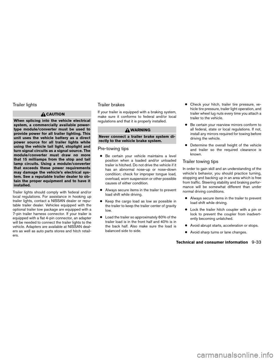
Trailer lights
CAUTION
When splicing into the vehicle electrical
system, a commercially available power-
type module/converter must be used to
provide power for all trailer lighting. This
unit uses the vehicle battery as a direct
power source for all trailer lights while
using the vehicle tail light, stoplight and
turn signal circuits as a signal source. The
module/converter must draw no more
that 15 milliamps from the stop and tail
lamp circuits. Using a module/converter
that exceeds these power requirements
may damage the vehicle’s electrical sys-
tem. See a reputable trailer dealer to ob-
tain the proper equipment and to have it
installed.
Trailer lights should comply with federal and/or
local regulations. For assistance in hooking up
trailer lights, contact a NISSAN dealer or repu-
table trailer dealer. Vehicles equipped with the
optional trailer tow package are equipped with a
7-pin trailer harness connector. If your trailer is
equipped with a flat 4-pin connector, an adapter
will be needed to connect the trailer lights to the
vehicle. Adapters are available at NISSAN deal-
ers as well as auto parts stores and hitch retail-
ers.
Trailer brakes
If your trailer is equipped with a braking system,
make sure it conforms to federal and/or local
regulations and that it is properly installed.
WARNING
Never connect a trailer brake system di-
rectly to the vehicle brake system.
Pre-towing tips
cBe certain your vehicle maintains a level
position when a loaded and/or unloaded
trailer is hitched. Do not drive the vehicle if it
has an abnormal nose-up or nose-down
condition; check for improper tongue load,
overload, worn suspension or other possible
causes of either condition.
cAlways secure items in the trailer to prevent
load shift while driving.
cKeep the cargo load as low as possible in
the trailer to keep the trailer center of gravity
low.
cLoad the trailer so approximately 60% of the
trailer load is in the front half and 40% is in
the back half. Also make sure the load is
balanced side to side.cCheck your hitch, trailer tire pressure, ve-
hicle tire pressure, trailer light operation, and
trailer wheel lug nuts every time you attach a
trailer to the vehicle.
cBe certain your rearview mirrors conform to
all federal, state or local regulations. If not,
install any mirrors required for towing before
driving the vehicle.
cDetermine the overall height of the vehicle
and trailer so the required clearance is
known.
Trailer towing tips
In order to gain skill and an understanding of the
vehicle’s behavior, you should practice turning,
stopping and backing up in an area which is free
from traffic. Steering stability and braking perfor-
mance will be somewhat different than under
normal driving conditions.
cAlways secure items in the trailer to prevent
load shift while driving.
cLock the trailer hitch coupler with a pin or
lock to prevent the coupler from inadvert-
ently becoming unlatched.
cAvoid abrupt starts, acceleration or stops.
cAvoid sharp turns or lane changes.
Technical and consumer information9-33
ZREVIEW COPYÐ2006 Truck/Frontier(d22)
Owners ManualÐUSA_English(nna)
10/17/05Ðdebbie
X
Page 325 of 336
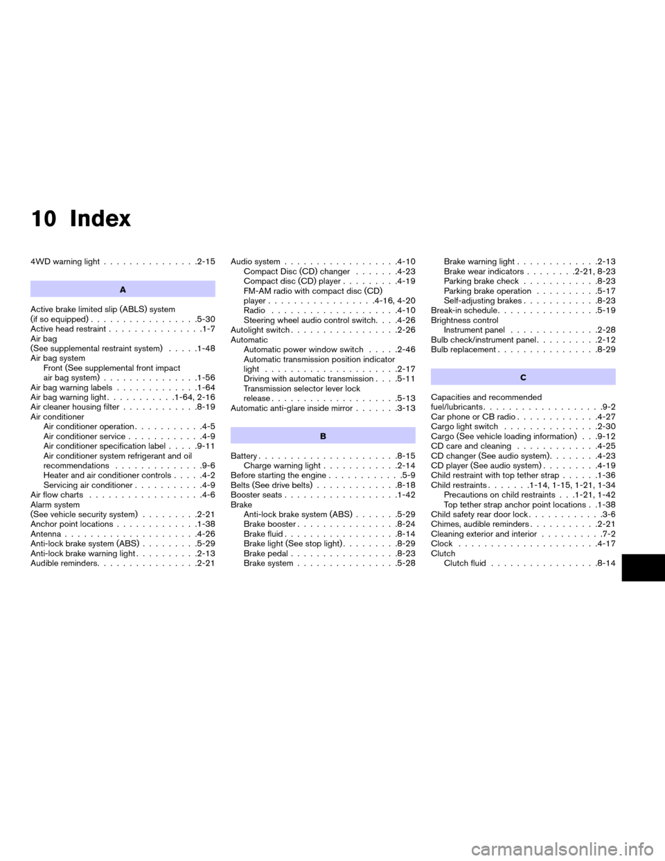
10 Index
4WD warning light...............2-15
A
Active brake limited slip (ABLS) system
(if so equipped).................5-30
Active head restraint...............1-7
Air bag
(See supplemental restraint system).....1-48
Air bag system
Front (See supplemental front impact
air bag system)...............1-56
Air bag warning labels.............1-64
Air bag warning light...........1-64, 2-16
Air cleaner housing filter............8-19
Air conditioner
Air conditioner operation...........4-5
Air conditioner service............4-9
Air conditioner specification label.....9-11
Air conditioner system refrigerant and oil
recommendations..............9-6
Heater and air conditioner controls.....4-2
Servicing air conditioner...........4-9
Air flow charts..................4-6
Alarm system
(See vehicle security system).........2-21
Anchor point locations.............1-38
Antenna.....................4-26
Anti-lock brake system (ABS).........5-29
Anti-lock brake warning light..........2-13
Audible reminders................2-21Audio system..................4-10
Compact Disc (CD) changer.......4-23
Compact disc (CD) player.........4-19
FM-AM radio with compact disc (CD)
player.................4-16, 4-20
Radio....................4-10
Steering wheel audio control switch. . . .4-26
Autolight switch.................2-26
Automatic
Automatic power window switch.....2-46
Automatic transmission position indicator
light.....................2-17
Driving with automatic transmission. . . .5-11
Transmission selector lever lock
release....................5-13
Automatic anti-glare inside mirror.......3-13
B
Battery......................8-15
Charge warning light............2-14
Before starting the engine............5-9
Belts (See drive belts).............8-18
Booster seats..................1-42
Brake
Anti-lock brake system (ABS).......5-29
Brake booster................8-24
Brake fluid..................8-14
Brake light (See stop light).........8-29
Brake pedal.................8-23
Brake system................5-28Brake warning light.............2-13
Brake wear indicators........2-21, 8-23
Parking brake check............8-23
Parking brake operation..........5-17
Self-adjusting brakes............8-23
Break-in schedule................5-19
Brightness control
Instrument panel..............2-28
Bulb check/instrument panel..........2-12
Bulb replacement................8-29
C
Capacities and recommended
fuel/lubricants...................9-2
Car phone or CB radio.............4-27
Cargo light switch...............2-30
Cargo (See vehicle loading information) . . .9-12
CD care and cleaning.............4-25
CD changer (See audio system)........4-23
CD player (See audio system).........4-19
Child restraint with top tether strap......1-36
Child restraints.......1-14, 1-15, 1-21, 1-34
Precautions on child restraints . . .1-21, 1-42
Top tether strap anchor point locations . .1-38
Child safety rear door lock............3-6
Chimes, audible reminders...........2-21
Cleaning exterior and interior..........7-2
Clock......................4-17
Clutch
Clutch fluid.................8-14
ZREVIEW COPYÐ2006 Truck/Frontier(d22)
Owners ManualÐUSA_English(nna)
10/17/05Ðdebbie
X