Page 89 of 297

�Do not use the hazard warning flash-
ers while moving on the highway un-
less unusual circumstances force you
to drive so slowly that your vehicle
might become a hazard to other traf-
fic.
�Turn signals do not work when the
hazard warning flasher lights are on.
The flasher will operate with the ignition switch in
any position.
To sound the horn, push the center pad area of
the steering wheel.
WARNING
Do not disassemble the horn. Doing so
could affect proper operation of the
supplemental front air bag system. Tam-
pering with the supplemental front air
bag system may result in serious per-
sonal injury.The seats are warmed by built-in heaters. The
switches are located on the center console.
1. Start the engine.
2. Select heat range.
�1For high heat, push the
(High) side
of the switch.
�2For low heat, push the
(Low) side of
the switch.
�3For no heat, the switch has a center OFF
position between low and high.
The indicator light
�A
in the switch will
illuminate when low or high is selected.
SIC2195
SIC3002
HORNHEATED SEATS (if so equipped)
2-28
Instruments and controls
�
06.1.17/Z33-D/V5.0
�
Page 90 of 297

The heater is controlled by a thermostat,
automatically turning the heater on and off.
The indicator light will remain on as long as
the switch is on.
3. When the vehicle’s interior is warmed, or
before you leave the vehicle, be sure to turn
the switch to the OFF position
�3.
An optional ventilated net seat has this built-in
heater only in the seat cushion part, not in the
seatback.
CAUTION
�The battery could be discharged if
the seat heater is operated while the
engine is not running.
�Do not use the seat heater for ex-
tended periods or when no one is
using the seat.
�Do not put anything on the seat
which insulates heat, such as a blan-
ket, cushion, seat cover, etc. Other-
wise, the seat may become over-
heated.
�Do not place anything hard or heavyon the seat or pierce it with a pin or
similar object. This may result in
damage to the heater.
�Any liquid spilled on the heated seat
should be removed immediately with
a dry cloth.
�When cleaning the seat, never use
gasoline, benzine, thinner, or any
similar materials.
�If any abnormalities are found or the
heated seat does not operate, turn
the switch off and have the system
checked by a NISSAN dealer.
The vehicle should be driven with the Vehicle
Dynamic Control (VDC) system on for most
driving conditions.
If the vehicle is stuck in mud or snow, the VDC
system reduces the engine output to reduce
wheel spin. The engine speed will be reduced
even if the accelerator is depressed to the floor.
If maximum engine power is needed to free a
stuck vehicle, turn the VDC system off.
To turn off the Vehicle Dynamic Control (VDC)
system, push the VDC OFF switch (located on
the lower side of the instrument panel). The
indicator light will come on.
Push the VDC OFF switch again or restart the
SIC1881
VEHICLE DYNAMIC CONTROL
(VDC) OFF SWITCH (if so
equipped)
Instruments and controls
2-29
�
06.1.17/Z33-D/V5.0
�
Page 91 of 297
engine to turn on the system. See “Vehicle
dynamic control (VDC) system” in the “5. Start-
ing and driving” section.
The vehicle should be driven with the Traction
Control System (TCS) on for most driving con-
ditions.
If the vehicle is stuck in mud or snow, the TCS
reduces the engine output to reduce wheel spin.
The engine speed will be reduced even if the
accelerator is depressed to the floor. If maximum
engine power is needed to free a stuck vehicle,
turn the TCS off.
To turn off the Traction Control System (TCS),
push the TCS OFF switch (located on the lower
side of the instrument panel). The
indicator
light will come on. Push it again or restart the
engine to turn the system back on.See “Traction control system (TCS)” in the “5.
Starting and driving” section.SIC1967
TRACTIONCONTROL SYSTEM
(TCS) OFF SWITCH (if so
equipped)
2-30
Instruments and controls
�
06.1.17/Z33-D/V5.0
�
Page 93 of 297

The power outlet is for powering electrical ac-
cessories such as cellular telephones.
CAUTION
�The outlet and plug may be hot dur-
ing or immediately after use.
�This power outlet is not designed for
use with a cigarette lighter unit.
�Do not use accessories that exceed a
combined power draw of 12 volt,
120W (10A) for both the front andrear power outlets. Do not use
double adapters or more than one
accessory with a single power outlet.
�Use power outlet with the engine
running to avoid discharging the ve-
hicle battery.
�Avoid using power outlets when the
air conditioner, headlights or rear
window defroster is on.
�Before inserting or disconnecting a
plug, be sure to turn off the power
switch of electrical accessory beingused or the ACC power of the vehicle.
�Push the plug in as far as it will go. If
good contact is not made, the plug
may overheat or the internal tem-
perature fuse may open.
�Do not allow water to contact the
outlet. When not in use, be sure to
close the lid.
SIC2258
Front
SIC1968
Rear
POWER OUTLET2-32
Instruments and controls
�
06.1.17/Z33-D/V5.0
�
Page 103 of 297

ignition switch has been turned to the OFF
position. To turn on the light again, turn the
ignition switch to the ONposition.
The map and vanity mirror lights will automati-
cally turn off 30 minutes after the latest operation
of the following with the ignition switch in the
ACC or OFF position:
�Opening or closing any door
�Locking or unlocking with the keyfob, a key or
the power door lock switch
�Inserting or removing a key from the ignition
switch
These lights will turn on again when any of the
above operations is performed after the lights
have turned off automatically. (The lights will turn
off 30 minutes after the latest operation of the
above as well.)
CAUTION
�Turn off the lights when you leave the
vehicle.
�Do not use for extended periods of
time with the engine stopped. This
could result in a discharged battery.The light on the vanity mirror will turn on when
the cover on the vanity mirror is opened.
When the vanity mirror light stays on, it will
automatically turn off 30 minutes after the
ignition switch has been turned to the OFF
position. To turn on the light again, turn the
ignition switch to the ONposition.The light illuminates when the rear hatch is
opened. When the rear hatch is closed, the light
will go off.
SIC1859
VANITY MIRROR LIGHT
LUGGAGE COMPARTMENT LIGHT
(Coupe models)
2-42
Instruments and controls
�
06.1.17/Z33-D/V5.0
�
Page 105 of 297

�Your vehicle’s engine should be
turned off while programming the
HomeLink
Universal Transceiver.
PROGRAMMING HomeLinkTo program your HomeLink
Transceiver to op-
erate a garage door, gate, or entry door opener,
home or office lighting, you need to be at the
same location as the device. Note: Garage door
openers (manufactured after 1996) have “rolling
code protection”. To program a garage door
opener equipped with “rolling code protection”;
you will need to use a ladder to get up to the
garage door opener motor to be able to access
the training button.1. To begin, press and hold the 2 outer
HomeLink
buttons (to clear the memory)
until the indicator light
�A
blinks (after 20
seconds). Release both buttons.
2. Position the end of the hand-held transmitter
1-3in(26-76mm)away from the
HomeLink
surface.3. Using both hands, simultaneously press and
hold both the HomeLink
button you want to
program and the hand-held transmitter but-
ton.
DO NOT release the buttons until step 4 has
been completed.
4. Hold down both buttons until the indicator
light on the HomeLinkflashes, changing
from a “slow blink” to a “rapid blink”. When
the indicator light flashes rapidly, both but-
tons may be released. The rapidly flashing
light indicates successful programming. To
activate the garage door or other pro-
grammed device, press and hold the pro-
grammed HomeLinkbutton - releasing
SIC3012
SIC3011
2-44
Instruments and controls
�
06.1.17/Z33-D/V5.0
�
Page 117 of 297
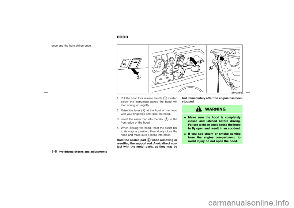
once and the horn chirps once.
1. Pull the hood lock release handle
�1
located
below the instrument panel; the hood will
then spring up slightly.
2. Raise the lever
�2
at the front of the hood
with your fingertips and raise the hood.
3. Insert the assist bar into the slot
�3
in the
front edge of the hood.
4. When closing the hood, reset the assist bar
to its original position, then slowly close the
hood and make sure it locks into place.
Hold the coated part
�A
when removing or
resetting the support rod. Avoid direct con-
tact with the metal parts, as they may behot immediately after the engine has been
stopped.
WARNING
�Make sure the hood is completely
closed and latched before driving.
Failure to do so could cause the hood
to fly open and result in an accident.
�If you see steam or smoke coming
from the engine compartment, to
avoid injury do not open the hood.
SPA2156
HOOD
3-8
Pre-driving checks and adjustments
�
06.1.17/Z33-D/V5.0
�
Page 122 of 297

3. Top side rail
4. Top latch lever
5. Soft top
6. Top storage lid
7. Trunk lid
8. Rear window
9. Rear section of th")
1. Soft top operating switch
2. Soft top indicator light (on the combination
meter)
3. Top side rail
4. Top latch lever
5. Soft top
6. Top storage lid
7. Trunk lid
8. Rear window
9. Rear section of the top
BEFORE OPERATING THE TOPThe soft top of your 350Z Roadster is electrically
operated. You can fully open or close the top
only by pressing the operating switch (on the
lower side of the instrument panel).
The soft top operating switch must be operated
under all of the following conditions:
�When the foot brake pedal is depressed.
�When the vehicle is stopped.
�When the engine is running.
CAUTION
Always keep the engine running while
operating the soft top. The top will also
operate when the ignition switch is in
the ONposition, but run the engine to
prevent a discharged battery.
Be sure to follow the operating instructions, and
all the warnings and cautions in this section.
Improper operation of the top could cause
a system malfunction, damage, or deterio-
ration of the top material and related parts.
WARNING
�Park the vehicle in a safe and level
place and apply the parking brake.
�Make sure the area is clear of ob-
stacles and there is enough clear-
ance over the top (for example, in a
garage or a covered area). More than
approximately 6.6 ft (2 m) from the
ground is required to open or close
the top safely. Otherwise, the top
may damage any objects above it
SPA1689
Interior/exterior view
SOFT TOP (Roadster models)
Pre-driving checks and adjustments
3-13
�
06.1.17/Z33-D/V5.0
�
 system” in the “5. Start-
ing and driving” section.
The vehicle should be driven with the Traction
Control System (TCS) on for")