Page 63 of 297

4. Driver supplemental air bag/Horn
5. Meters/gauges6. Cruise contro")
1. Headlight/turn signal switch
2. Instrument brightness control switch
3. Steering wheel switch for audio control (if so
equipped)
4. Driver supplemental air bag/Horn
5. Meters/gauges6. Cruise control main/set switch
(if so equipped)
7. Trip computer mode/setting switch
8. Wiper/washer switch
9. Center ventilator
10. Card holder11. Passenger supplemental air bag
12. Side ventilator
13. VDC (Vehicle dynamic control) OFF switch
or TCS (Traction control system) OFF
switch
14. Soft top operating switch (for Roadster
models)
15. Fuel-filler door opener switch
16. Hood lock release handle
17. Fuse box
18. Tilting steering wheel lock lever
19. Ignition switch/steering lock
20. Navigation system display* or Instrument
pocket
21. Audio system/Clock
22. Rear window and outside mirror defroster
switch
23. Hazard warning flasher switch
24. Cup holder
25. Heated seat switch (if so equipped)
26. Heater/air conditioner control
27. Power outlet
*: Refer to the separate Navigation System
Owner’s Manual.
SIC2996
INSTRUMENT PANEL2-2
Instruments and controls
�
06.1.17/Z33-D/V5.0
�
Page 70 of 297

Switches for the trip computer are located on
the side of the combination meter panel. To
operate the trip computer, push the side of the
switches as shown above.�A: Trip computer mode switch
�B: Trip computer setting switch
When the ignition switch is turned to ON, modes
of the trip computer can be selected by pushing
the trip computer mode switch
�A.
Each time the mode switch
�A
is pushed, the
display will change as follows:
Speed indicator→Outside air temperature
(ICY)→Distance to empty (dte)→Average fuelconsumption and speed→Elapsed time and
trip odometer→Stopwatch→Tire pressure
indicator (PSI)→Up-shift indicator setting (for
M/T models)→Speed indicator
Speed indicator (mph or km/h)The vehicle speed is displayed in MPH or km/h
while driving.
The speed indicator in the trip computer
indicates the reference speed. The actual
speed indicated by the speedometer (com-
bination meter) may differ from the one in
the trip computer.Outside air temperature
(ICY—°For°C)The outside air temperature is displayed in °F or
°C in the range of −22 to 131°F (−30 to 55°C).
The outside air temperature mode includes a low
temperature warning feature: below 37°F (3°C),
the outside air temperature mode is automati-
cally selected and the ICY indicator will illumi-
nate in order to draw the driver’s attention. Push
the mode switch
�A
if you wish to return to the
mode that was selected before the warning
occurred. The ICY indicator will continue blink-
ing as long as the temperature remains below
39°F (4°C).
The ambient temperature sensor is located infront of the radiator. The sensor may be affected
by road or engine heat, wind directions and
other driving conditions. The display may differ
from the actual ambient temperature or the
temperature displayed on various signs or bill-
boards.
Distance to empty (dte — mls or km)The distance to empty (dte) mode provides you
with an estimation of the distance that can be
driven before refueling. The dte is constantly
being calculated, based on the amount of fuel in
the fuel tank and the actual fuel consumption.
The display is updated every 30 seconds.
The dte mode includes a low range warning
feature: when the fuel level is low, the dte mode
is automatically selected and the digits blink in
order to draw the driver’s attention. Press the
mode switch
�Aif you wish to return to the mode
that was selected before the warning occurred.
The dte indicator will remain blinking until the
vehicle is refuelled.
When the fuel level drops even lower, the dte
display will change to (----).
NOTE:
�If the amount of fuel added while the
ignition switch is OFF is small, the dis-
play just before the ignition switch is
SIC2997
Instruments and controls
2-9
�
06.1.17/Z33-D/V5.0
�
Page 88 of 297

TURN SIGNAL SWITCH�1
Turn signal
Move the lever up or down to signal the turning
direction. When the turn is completed, the turn
signals cancel automatically.�2
Lane change signal
To indicate a lane change, move the lever up or
down to the point where lights begin flashing.
INSTRUMENT BRIGHTNESS
CONTROLThe instrument brightness control operates
when the light switch is in the
or
position and the ignition switch is in the
ON position.
To adjust the brightness of instrument panel
lights, press the control switches located on the
left side of the meter panel. Pressing the upper
switch�A
will brighten the lights. The lower
switch
�B
will dim the lights. Repeatedly press-
ing the lower switch will turn the lights off.Push the switch (located on the front part of the
center console) on to warn other drivers when
you must stop or park under emergency condi-
tions. All turn signal lights will flash.
Some state or provincial laws may prohibit
the use of the hazard warning flasher
switch while driving.
WARNING
�If stopping for an emergency, be sure
to move the vehicle well off the road.
SIC1963
SIC3001
SIC2475
HAZARD WARNING FLASHER
SWITCH
Instruments and controls
2-27
�
06.1.17/Z33-D/V5.0
�
Page 90 of 297

The heater is controlled by a thermostat,
automatically turning the heater on and off.
The indicator light will remain on as long as
the switch is on.
3. When the vehicle’s interior is warmed, or
before you leave the vehicle, be sure to turn
the switch to the OFF position
�3.
An optional ventilated net seat has this built-in
heater only in the seat cushion part, not in the
seatback.
CAUTION
�The battery could be discharged if
the seat heater is operated while the
engine is not running.
�Do not use the seat heater for ex-
tended periods or when no one is
using the seat.
�Do not put anything on the seat
which insulates heat, such as a blan-
ket, cushion, seat cover, etc. Other-
wise, the seat may become over-
heated.
�Do not place anything hard or heavyon the seat or pierce it with a pin or
similar object. This may result in
damage to the heater.
�Any liquid spilled on the heated seat
should be removed immediately with
a dry cloth.
�When cleaning the seat, never use
gasoline, benzine, thinner, or any
similar materials.
�If any abnormalities are found or the
heated seat does not operate, turn
the switch off and have the system
checked by a NISSAN dealer.
The vehicle should be driven with the Vehicle
Dynamic Control (VDC) system on for most
driving conditions.
If the vehicle is stuck in mud or snow, the VDC
system reduces the engine output to reduce
wheel spin. The engine speed will be reduced
even if the accelerator is depressed to the floor.
If maximum engine power is needed to free a
stuck vehicle, turn the VDC system off.
To turn off the Vehicle Dynamic Control (VDC)
system, push the VDC OFF switch (located on
the lower side of the instrument panel). The
indicator light will come on.
Push the VDC OFF switch again or restart the
SIC1881
VEHICLE DYNAMIC CONTROL
(VDC) OFF SWITCH (if so
equipped)
Instruments and controls
2-29
�
06.1.17/Z33-D/V5.0
�
Page 91 of 297
engine to turn on the system. See “Vehicle
dynamic control (VDC) system” in the “5. Start-
ing and driving” section.
The vehicle should be driven with the Traction
Control System (TCS) on for most driving con-
ditions.
If the vehicle is stuck in mud or snow, the TCS
reduces the engine output to reduce wheel spin.
The engine speed will be reduced even if the
accelerator is depressed to the floor. If maximum
engine power is needed to free a stuck vehicle,
turn the TCS off.
To turn off the Traction Control System (TCS),
push the TCS OFF switch (located on the lower
side of the instrument panel). The
indicator
light will come on. Push it again or restart the
engine to turn the system back on.See “Traction control system (TCS)” in the “5.
Starting and driving” section.SIC1967
TRACTIONCONTROL SYSTEM
(TCS) OFF SWITCH (if so
equipped)
2-30
Instruments and controls
�
06.1.17/Z33-D/V5.0
�
Page 95 of 297
CAUTION
�Do not use for anything other than
glasses.
�Do not leave sunglasses in the sun-
glasses holder while parking in direct
sunlight. The heat may damage the
sunglasses.
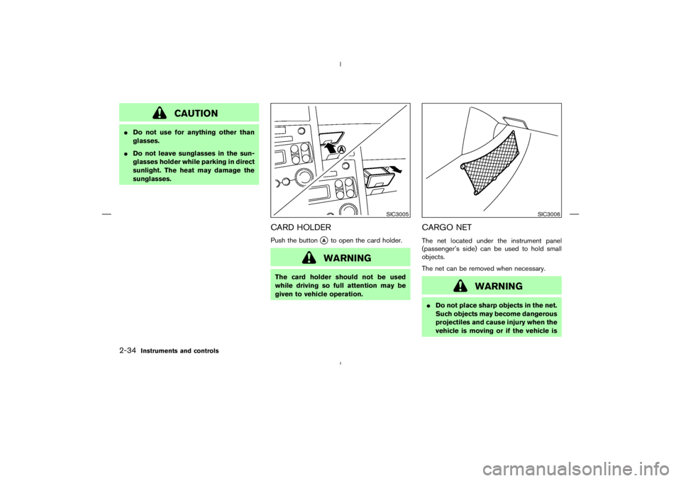
CARD HOLDERPush the button
�A
to open the card holder.WARNING
The card holder should not be used
while driving so full attention may be
given to vehicle operation.
CARGO NETThe net located under the instrument panel
(passenger’s side) can be used to hold small
objects.
The net can be removed when necessary.
WARNING
�Do not place sharp objects in the net.
Such objects may become dangerous
projectiles and cause injury when the
vehicle is moving or if the vehicle is
SIC3005
SIC3006
2-34
Instruments and controls
�
06.1.17/Z33-D/V5.0
�
Page 102 of 297

AUTOMATIC ADJUSTING
FUNCTION
CAUTION
When the battery cable is removed from
the battery terminal, do not close either
of the front doors. The automatic win-
dow adjusting function will not work,
and the side roof panel/top side rail
may be damaged.
The power window has an automatic adjusting
function. When the door is being opened, the
window is automatically lowered slightly to avoid
contact between the window and the side roof
panel/top side rail. When the door is closed, the
window is automatically raised slightly.
ROOM LIGHTThe interior light has a two-position switch. (
�A:
DOOR,
�B: OFF)
When the switch is in the DOOR position, the
light will illuminate when a door is opened.
The light will stay on for about 30 seconds when:
�The doors are unlocked by the keyfob, a key
or the power door lock switch while all doors
are closed.
�The driver’s door is opened and then closed
while the key is removed from the ignition
switch.�The key is removed from the ignition switch
while all doors are closed.
The interior light will turn off while the 30 second
timer is activated, when:
�The driver’s door is locked either with the
keyfob, a key or the power door lock switch.
�The ignition switch is turned ON.
MAP LIGHTSTo turn on the light, push the plastic surface
�C
of the light. Push it again to turn off the light.
When the map light stays on, it will auto-
matically turn off 30 minutes after the
SIC1980A
Coupe models
SIC2238
Roadster models
INTERIOR LIGHTS
Instruments and controls
2-41
�
06.1.17/Z33-D/V5.0
�
Page 117 of 297
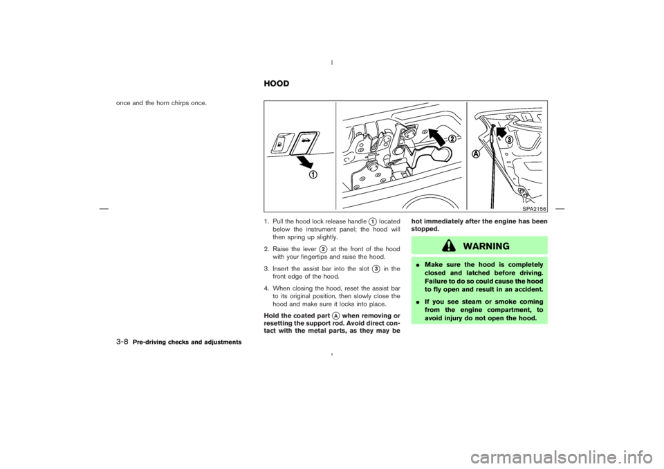
once and the horn chirps once.
1. Pull the hood lock release handle
�1
located
below the instrument panel; the hood will
then spring up slightly.
2. Raise the lever
�2
at the front of the hood
with your fingertips and raise the hood.
3. Insert the assist bar into the slot
�3
in the
front edge of the hood.
4. When closing the hood, reset the assist bar
to its original position, then slowly close the
hood and make sure it locks into place.
Hold the coated part
�A
when removing or
resetting the support rod. Avoid direct con-
tact with the metal parts, as they may behot immediately after the engine has been
stopped.
WARNING
�Make sure the hood is completely
closed and latched before driving.
Failure to do so could cause the hood
to fly open and result in an accident.
�If you see steam or smoke coming
from the engine compartment, to
avoid injury do not open the hood.
SPA2156
HOOD
3-8
Pre-driving checks and adjustments
�
06.1.17/Z33-D/V5.0
�
 system” in the “5. Start-
ing and driving” section.
The vehicle should be driven with the Traction
Control System (TCS) on for")