Page 67 of 800
Page 68 of 800

CHARGING SYSTEM
ENGINE ELECTRICAL16-6
9. Check that the reading on the voltmeter is equal
to the battery voltage.
NOTE: If the voltage is 0 V, the cause is probably
an open circuit in the wire or fusible link between
the alternator "B" terminal and the battery (+) ter
-
minal.
10.Turn the light switch on to turn on headlamps and
then start the engine.
11.Immediately after setting the headlamps to high
beam and turning the heater blower switch to the
high revolution position, increase the engine
speed to 2,500 r/min and read the maximum
current output value displayed on the ammeter.
Limit: 70 % of normal current output
NOTE: .
•For the nominal current output, refer to the
Alternator Specifications.
•Because the current from the battery will soon
drop after the engine is started, the above step
should be carried out as quickly as possible in
order to obtain the maximum current output
value.
•The current output value will depend on the
electrical load and the temperature of the
alternator body.
•If the electrical load is small while testing, the
specified level of current may not be output
even though the alternator is normal. In such
cases, increase the electrical load by leaving
the headlamps turned on for some time to dis
-
charge the battery or by using the lighting sys-
tem in another vehicle, and then test again.
•The specified level of current also may not be
output if the temperature of the alternator body
or the ambient temperature is too high. In such
cases, cool the alternator and then test again.
12.The reading on the ammeter should be above the
limit value. If the reading is below the limit value
and the alternator output wire is normal, remove
the alternator from the engine and check the
alternator.
13.Run the engine at idle after the test.
14.Turn the ignition switch to the "LOCK" (OFF)
position.
15.Remove the tachometer or the M.U.T.-II/III.
16.Disconnect the negative battery cable.
17.Disconnect the ammeter and voltmeter.
18.Connect the negative battery cable.
Page 69 of 800
Page 70 of 800
CHARGING SYSTEM
ENGINE ELECTRICAL16-8
If the voltage is not within the standard value,
there is a malfunction of the voltage regulator or of
the alternator.
14.After the test, lower the engine speed to the idle speed.
15.Turn the ignition switch to the "LOCK" (OFF) position.
16.Remove the tachometer or the M.U.T.-II/III.
17.Disconnect the negative battery cable.
18.Disconnect the ammeter and voltmeter.
19.Connect the alternator output wire to the alternator "B" terminal.
20.Remove the special tool, and return the connector
to the original condition.
21.Connect the negative battery cable.
Voltage Regulation Table
Standard value:
Inspection terminalVoltage regulator ambient
temperature
°C
Voltage V
Terminal "S"−2014.2 − 15.4
2013.9 − 14.9
6013.4 − 14.6
8013.1 − 14.5
Page 71 of 800

CHARGING SYSTEM
ENGINE ELECTRICAL16-9
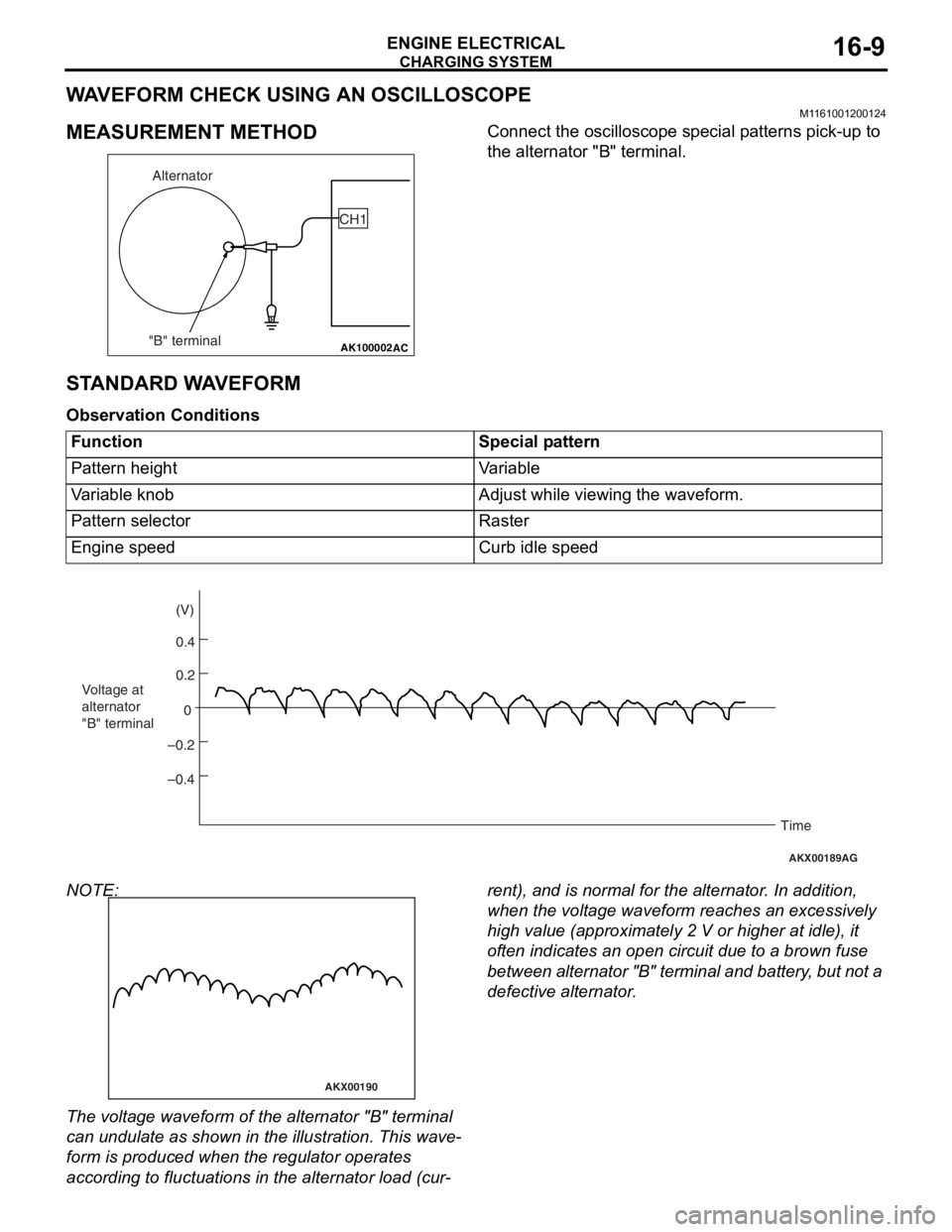
WAVEFORM CHECK USING AN OSCILLOSCOPE
M1161001200124
MEASUREMENT METHOD
AK100002
Alternator
"B" terminal CH1
AC
Co
nnect the oscillo scope specia l p a tt erns p i ck-up to
the alternato
r "B" terminal.
STANDARD W A VEFORM
Observ ation Conditi ons
FunctionSpecial pattern
Pattern heightVariable
Variable knobAdjust while viewing the waveform.
Pattern selectorRaster
Engine speedCurb idle speed
AKX00189
0.4 (V)
0.2
0
–0.2
–0.4
Voltage at
alternator
"B" terminal
Time
AG
NOTE:
AKX00190
The volt age waveform of th e alte rnator "B" t e rminal
can u
ndulate as sho w n in th e illustratio n . This wave
-
form is produce d when t he regu lator operate s
accordin
g to fluctu ation s in the alterna t or loa d (cu r
-
rent), and is normal fo r the alterna t or . In ad dition,
wh
en the volt ag e wavef o rm re ache s an excessively
high
value (app roximate ly 2 V or higher at idle ), it
of
ten indicates an o pen circuit du e to a brown fuse
be
twe e n a l te rn at or "B " t e r m in al an d ba tt er y , b u t n o t a
defective alte
rnator .
Page 72 of 800
CHARGING SYSTEM
ENGINE ELECTRICAL16-10
EXAMPLE OF ABNORMAL WAVEFORMS
NOTE: .
1. The size of the waveform patterns differs largely, depending on the adjustment of the variable knob on the
oscilloscope.
2. Identification of abnormal waveforms is easier when th ere is a large output current (regulator is not oper-
ating). (Waveforms can be observed when the headlamps are illuminated.)
3. Check the conditions of the charging warning lamp (illuminated/not illum inated). Also, check the charging
system totally.
Abnormal waveformProblem cause
Example 1
AKX00191
Open diod e
Exampl e 2
AKX00192
Shor t in diode
Page 73 of 800
CHARGING SYSTEM
ENGINE ELECTRICAL16-11
Example 3
AKX00193
Broken wire in
stator coil
Examp l e 4
AKX00194
Shor t in st ator
coil
Exampl e 5
AKX00195
At this time, the charg i ng warn ing lamp is illuminated .
Open
suppleme
n t a ry
d
i ode
Abn o rm al waveform P roble m caus e
Page 74 of 800
CHARGING SYSTEM
ENGINE ELECTRICAL16-12
ALTERNATOR ASSEMBLY
REMOVAL AND INSTALLATION <4G1>
M1161001400548
Pre-removal Operation
•Under Cover Removal
•Drive Belt Removal (Refer to GROUP 11A - Crankshaft
Pulley
P.11A-16).
Post-installation Operation
•Drive Belt Installation (Refer to GROUP 11A - Crankshaft
Pulley P.11A-16).
•Drive Belt Tension Adjustment (Refer to GROUP 11A -
On-vehicle Service P.11A-7).
•Under Cover Installation
AC303729
1
2
4
3
44 ± 10 N·m
23 ± 2 N·m 24 ± 3 N·m 12 ± 2 N·m
AB
13 ± 3 N·m
Removal steps
1.Power steering pressure hose
clamp
2.Alternator connector and terminal
3.Alternator adjusting brace
<>4.Alternator assembly
REMOV
A L SER VICE POINT
<> ALTERNA T O R ASSEMBL Y
REMOV
A L
Remove the a l tern ator assembly from above the
vehicle.