Page 71 of 800

CHARGING SYSTEM
ENGINE ELECTRICAL16-9
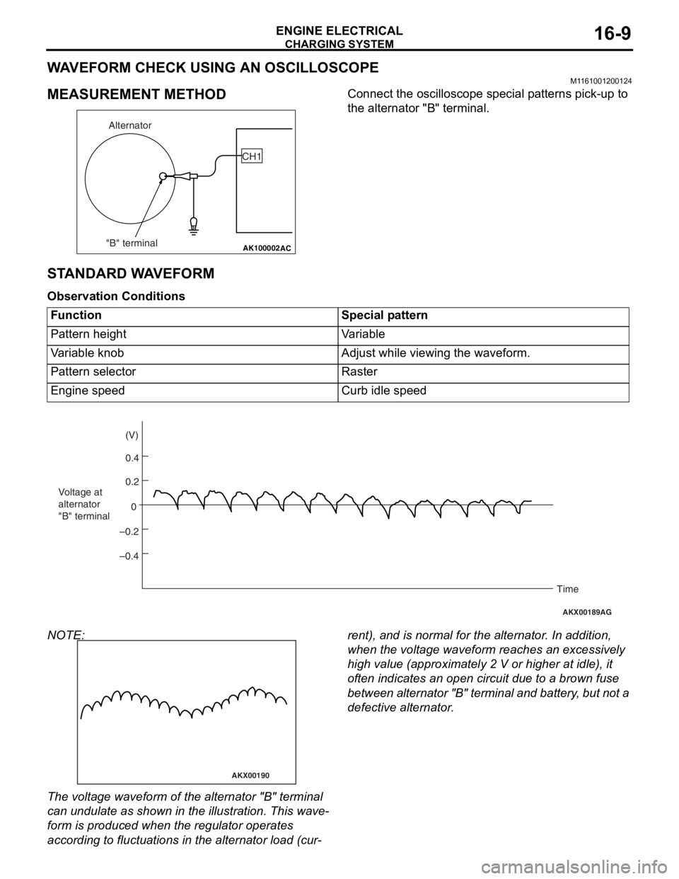
WAVEFORM CHECK USING AN OSCILLOSCOPE
M1161001200124
MEASUREMENT METHOD
AK100002
Alternator
"B" terminal CH1
AC
Co
nnect the oscillo scope specia l p a tt erns p i ck-up to
the alternato
r "B" terminal.
STANDARD W A VEFORM
Observ ation Conditi ons
FunctionSpecial pattern
Pattern heightVariable
Variable knobAdjust while viewing the waveform.
Pattern selectorRaster
Engine speedCurb idle speed
AKX00189
0.4 (V)
0.2
0
–0.2
–0.4
Voltage at
alternator
"B" terminal
Time
AG
NOTE:
AKX00190
The volt age waveform of th e alte rnator "B" t e rminal
can u
ndulate as sho w n in th e illustratio n . This wave
-
form is produce d when t he regu lator operate s
accordin
g to fluctu ation s in the alterna t or loa d (cu r
-
rent), and is normal fo r the alterna t or . In ad dition,
wh
en the volt ag e wavef o rm re ache s an excessively
high
value (app roximate ly 2 V or higher at idle ), it
of
ten indicates an o pen circuit du e to a brown fuse
be
twe e n a l te rn at or "B " t e r m in al an d ba tt er y , b u t n o t a
defective alte
rnator .
Page 72 of 800
CHARGING SYSTEM
ENGINE ELECTRICAL16-10
EXAMPLE OF ABNORMAL WAVEFORMS
NOTE: .
1. The size of the waveform patterns differs largely, depending on the adjustment of the variable knob on the
oscilloscope.
2. Identification of abnormal waveforms is easier when th ere is a large output current (regulator is not oper-
ating). (Waveforms can be observed when the headlamps are illuminated.)
3. Check the conditions of the charging warning lamp (illuminated/not illum inated). Also, check the charging
system totally.
Abnormal waveformProblem cause
Example 1
AKX00191
Open diod e
Exampl e 2
AKX00192
Shor t in diode
Page 73 of 800
CHARGING SYSTEM
ENGINE ELECTRICAL16-11
Example 3
AKX00193
Broken wire in
stator coil
Examp l e 4
AKX00194
Shor t in st ator
coil
Exampl e 5
AKX00195
At this time, the charg i ng warn ing lamp is illuminated .
Open
suppleme
n t a ry
d
i ode
Abn o rm al waveform P roble m caus e
Page 74 of 800
CHARGING SYSTEM
ENGINE ELECTRICAL16-12
ALTERNATOR ASSEMBLY
REMOVAL AND INSTALLATION <4G1>
M1161001400548
Pre-removal Operation
•Under Cover Removal
•Drive Belt Removal (Refer to GROUP 11A - Crankshaft
Pulley
P.11A-16).
Post-installation Operation
•Drive Belt Installation (Refer to GROUP 11A - Crankshaft
Pulley P.11A-16).
•Drive Belt Tension Adjustment (Refer to GROUP 11A -
On-vehicle Service P.11A-7).
•Under Cover Installation
AC303729
1
2
4
3
44 ± 10 N·m
23 ± 2 N·m 24 ± 3 N·m 12 ± 2 N·m
AB
13 ± 3 N·m
Removal steps
1.Power steering pressure hose
clamp
2.Alternator connector and terminal
3.Alternator adjusting brace
<>4.Alternator assembly
REMOV
A L SER VICE POINT
<> ALTERNA T O R ASSEMBL Y
REMOV
A L
Remove the a l tern ator assembly from above the
vehicle.
Page 75 of 800
CHARGING SYSTEM
ENGINE ELECTRICAL16-13
REMOVAL AND INSTALLATION <4G6>
M1161001401347
Pre-removal Operation
•Battery and Battery Tray Removal
•Under Cover Removal
•Strut Tower Bar Removal (Refer to GROUP 42 P.42-9).
•Drive Belt Removal (Refer to GROUP 11C - Crankshaft
Pulley P.11C-16).
•Air Cleaner Assembly Remo val (Refer to GROUP 15 P.15-3).
Post-installation Operation
•Air Cleaner Assembly Installation (Refer to GROUP 15 P.15-3).
•Drive Belt Installation (Refer to GROUP 11C - Crankshaft
Pulley P.11C-16).
•Strut Tower Bar Installation (Refer to GROUP 42 P.42-9).
•Drive Belt Tension Adjustment (Refer to GROUP 11C -
On-vehicle Service
P.11C-7).
•Under Cover Installation
•Battery and Battery Tray Installation
AC504936
1 1
2
3
18 ± 3 N·m 12 ± 2 N·m
AB
Removal steps
1.Shift cable connection<>2.Shift cable and shift cable bracket
assembly
3.Vehicle speed sensor connector
Removal steps (Continued)
Page 76 of 800
Page 77 of 800
Page 78 of 800