2006 MITSUBISHI COLT drive
[x] Cancel search: drivePage 108 of 364

DIAGNOSIS SYSTEM
MULTIPOINT FUEL INJECTION (MPI) <4A9>13A-14
DIAGNOSIS SYSTEM
M2132009000882
Engine-ECU
been provided with the following functions for easier
system inspection.FREEZE-FRAME DATA
When the engine-ECU
diagnosis code, the engine condition at that time is
also memorized. The M.U.T.-III can then be used to
analyze this data in order to increase the effective
-
ness of troubleshooting. The freeze-frame data dis-
play items are given below.
Item No.DataUnit
13Intake air temperature sensor°C
21Engine coolant temperature sensor°C
22Crank angle sensorr/min
24Vehicle speed sensorkm/h
32Manifold absolute pressure sensorkPa
44Ignition advancedeg
81Long-term fuel compensation%
82Short-term fuel compensation%
87Calculated load value%
88Fuel control conditionOpen loopOL
Closed loopCL
Open loop owing to drive conditionOL-DRV
Open loop owing to system malfunctionOL-SYS
Closed loop based on one oxygen sensorCL-HO2S
8AThrottle position sensor (main)%
A1Oxygen sensor (front)V
A2Oxygen sensor (rear)V
DIAGNOSIS CODE
The diagnosis and engine warning lamp items are
given in the table below.
Code No.Diagnosis itemMain diagnosis contentsEngine
warning lamp
P0011Variable valve timing systemAbnormal MIVEC system−
P0105Manifold absolute pressure sensor
systemOpen circuit or short-circuit in
sensor-related circuitsON
P0110Intake air temperature sensor
systemOpen circuit or short-circuit in
sensor-related circuitsON
P0115Engine coolant temperature sensor
systemOpen circuit or short-circuit in
sensor-related circuitsON
P0122*Throttle position sensor (main)
circuit low inputOpen circuit or short-circuit in
sensor-related circuitsON
P0123*Throttle position sensor (main)
circuit high inputShort-circuit in sensor-related
circuitsON
Page 111 of 364

DIAGNOSIS SYSTEM
MULTIPOINT FUEL INJECTION (MPI) <4A9>13A-17
DATA LIST FUNCTION
The data list items are given in the table below
Item No.Inspection itemUnit
11Oxygen sensor (front)mV
13Intake air temperature sensor°C
14Throttle position sensor (sub)mV
16Power supply voltageV
18Cranking signal (ignition switch-ST)ON/OFF
21Engine coolant temperature sensor°C
22Crank angle sensorr/min
25Barometric pressure sensorkPa
29Inhibitor switchP or N/D, DS, L, or R
32Manifold absolute pressure sensorkPa
41Injectorsms
44Ignition advanceBTDC
49A/C relayON/OFF
59Oxygen sensor (rear)mV
67Stop lamp switchON/OFF
68Exhaust gas recirculation valveSTEP
77Accelerator pedal position sensor (sub)mV
78Accelerator pedal position sensor (main)mV
79Throttle position sensor (main)mV
7EVariable valve timing phase angleCA
13*Intake air temperature sensor°C
21*Engine coolant temperature sensor°C
22*Crank angle sensorr/min
24*Vehicle speed sensorkm/h
32*Manifold absolute pressure sensorkPa
44*Ignition advancedeg
81*Long-term fuel compensation%
82*Short-term fuel compensation%
87*Calculated load value%
88*Fuel control conditionOpen loopOL
Closed loopCL
Open loop owing to drive
conditionOL-DRV
Open loop owing to system
malfunctionOL-SYS
Closed loop based on one
oxygen sensorCL-HO2S
Page 114 of 364

DIAGNOSIS SYSTEM
MULTIPOINT FUEL INJECTION (MPI) <4A9>13A-20
ACTUATOR TEST FUNCTION
The actuator test items are given in the table below
Item No.Inspection itemDrive contents
01InjectorsCut fuel to No.1 injector
02Cut fuel to No.2 injector
03Cut fuel to No.3 injector
04Cut fuel to No.4 injector
07Fuel pumpFuel pump operates
08Purge control solenoid valveSolenoid valve turns from OFF to ON
17Basic ignition timingSet to ignition adjustment mode
20Cooling fan control relayDrive the fan motor
34Throttle valve control servoStop the throttle valve control servo
Page 119 of 364

GENERAL INFORMATION
MULTIPOINT FUEL INJECTION (MPI) <4G1>13B-5
List of Component Functions
ECU
NameFunction
Engine-ECUThe signals that are input by the sensors enable the
actuators to be controlled in accordance with the
driving conditions.
Sensor
Ignition switch-IGThis signal indicates the ON/OFF condition of the
ignition switch. When this signal is input, the
engine-ECU supplies power to the crank angle
sensor, camshaft position sensor, etc.
Ignition switch-STThis signal indicates that the engine is cranking.
Based on this signal, the engine-ECU controls the
fuel injection, throttle valve position, and the injection
timing that are suited for starting the engine.
Air flow sensor This signal, which indicates the intake air flow rate
(mass), is input into the engine-ECU. Based on the
signals from this sensor, the engine-ECU effects fuel
injection control.
Oxygen sensor
electrodes, detects the level of oxygen concentration
in the exhaust gases. The engine-ECU determines
whether the air-fuel ratio is at the optimal
stoichiometric ratio in accordance with this oxygen
concentration level.
Barometric pressure sensorThis sensor detects the altitude of the vehicle. It
enables the engine-ECU to make fuel injection
volume corrections in order to achieve an appropriate
air-fuel ratio.
Intake air temperature sensorThis sensor, which contains a thermistor, detects the
temperature of the intake air. The engine-ECU
makes fuel injection volume corrections that suit the
intake air temperature, in accordance with the
voltage that is output by this sensor.
Engine coolant temperature sensorThis sensor, which contains a thermistor, detects the
temperature of the engine coolant. The engine-ECU
determines the warm-up condition of the engine in
accordance with the voltage that is output by this
sensor, in order to control the fuel injection volume,
idle speed, and ignition timing.
Throttle position sensor
and inputs it into the engine-ECU. Based on the
voltage that is output by this sensor, the engine-ECU
effects throttle valve feedback control.
Accelerator pedal position sensor
and inputs it into the engine-ECU. Based on the
voltage that is output by this sensor, which
determines the accelerator position (and the intention
of the driver), the engine-ECU effects appropriate
fuel injection and throttle valve position controls.
Page 122 of 364
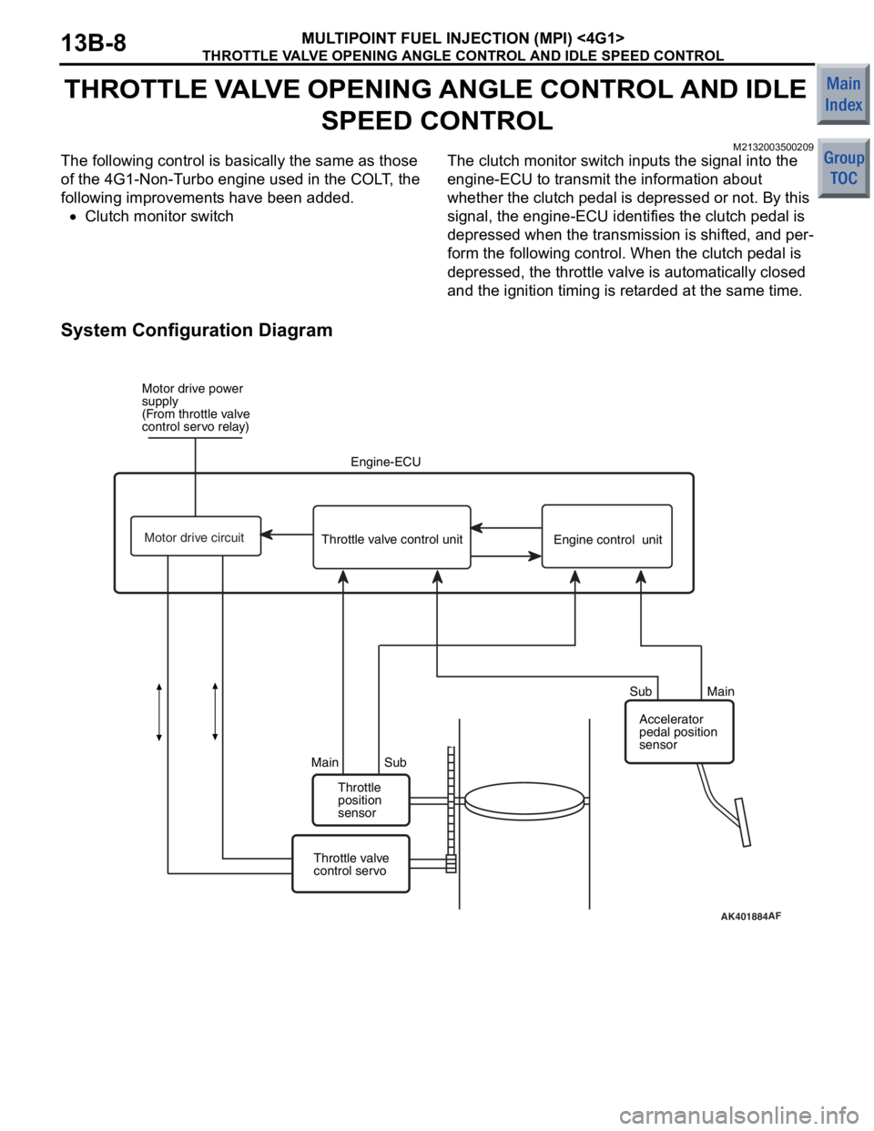
THROTTLE VALVE OPENING ANGLE CONTROL AND IDLE SPEED CONTROL
MULTIPOINT FUEL INJECTION (MPI) <4G1>13B-8
THROTTLE VALVE OPENING ANGLE CONTROL AND IDLE
SPEED CONTROL
M2132003500209
The following control is basically the same as those
of the 4G1-Non-Turbo engine used in the COLT, the
following improvements have been added.
•Clutch monitor switch
The clutch monitor switch inputs the signal into the
engine-ECU to transmit the information about
whether the clutch pedal is depressed or not. By this
signal, the engine-ECU identifies the clutch pedal is
depressed when the transmission is shifted, and per
-
form the following control. When the clutch pedal is
depressed, the throttle valve is automatically closed
and the ignition timing is retarded at the same time.
System Configuration Diagram
AK401884AF
Motor drive power
supply
(From throttle valve
control servo relay)
Engine-ECU
Throttle
position
sensor
Main Sub Sub Main
Throttle valve
control servo Accelerator
pedal position
sensor
Throttle valve control unit
Engine control unit
Motor drive circuit
Page 124 of 364

FUEL PRESSURE CONTROL
MULTIPOINT FUEL INJECTION (MPI) <4G1>13B-10
FUEL PRESSURE CONTROL
M2132020000069
Normally, the negative pressure in the intake mani-
fold acts upon the fuel pressure regulator to maintain
the fuel pressure at a constant level with regard to
the pressure inside the intake manifold, causing the
amount of fuel injected to be controlled proportion to
the injector drive time. However, if the engine is
started while the engine coolant temperature and the
intake air temperature are high, the engine-ECU makes current flow to the fuel pressure control sole
-
noid valve to activate the fuel pressure regulator by
means of atmospheric pressure. Because of this, the
generation of fuel vapour due to the high fuel pres
-
sure and high temperature is avoided, and the idling
stability immediately after restarting the engine at
high temperature is maintained.
AK402663
To fuel
tank
From
fuel
pump
Fuel pressure
regulator
Fuel pressure
control solenoid
AB
Engine control
relay
Engine coolant temperature
sensorIntake air temperature
sensor
Engine-ECU
Battery
Page 128 of 364

DIAGNOSIS SYSTEM
MULTIPOINT FUEL INJECTION (MPI) <4G1>13B-14
DIAGNOSIS SYSTEM
M2132009000893
Engine-ECU has been provided with the following
functions for easier system inspection.FREEZE-FRAME DATA
When the engine-ECU detects a problem and stores
the resulting diagnosis code, the engine condition at
that time is also memorized. The M.U.T.-III can then
be used to analyze this data in order to increase the
effectiveness of troubleshooting. The freeze-frame
data display items are given below.
Item No.DataUnit
12Air flow sensorg/sec
13Intake air temperature sensor°C
21Engine coolant temperature sensor°C
22Crank angle sensorr/min
24Vehicle speed signalkm/h
44Ignition advancedeg
79Throttle position sensor (main)mV
81Long-term fuel compensation%
82Short-term fuel compensation%
87Calculated load value%
88Fuel control conditionOpen loopOL
Closed loopCL
Open loop owing to drive conditionOL-DRV
Open loop owing to system malfunctionOL-SYS
89Fuel control condition−
DIAGNOSIS CODE
The diagnosis and engine warning lamp items are
given in the table below.
Code No.Diagnosis itemMain diagnosis contentsEngine
warning lamp
P0011Variable valve timing systemAbnormal oil passage in variable
valve timing system−
P0090Fuel pressure control solenoid
valve systemOpen circuit or short-circuit in
solenoid valve-related circuitON
P0100Air flow sensor systemOpen circuit or short-circuit in
valve-related circuitsON
P0105Barometric pressure sensor
systemOpen circuit or short-circuit in
sensor-related circuitsON
P0110Intake air temperature sensor
systemOpen circuit or short-circuit in
sensor-related circuitsON
P0115Engine coolant temperature sensor
systemOpen circuit or short-circuit in
sensor-related circuitsON
P0122Throttle position sensor (main)
circuit low inputOpen circuit or short-circuit in
sensor-related circuitsON
Page 132 of 364

DIAGNOSIS SYSTEM
MULTIPOINT FUEL INJECTION (MPI) <4G1>13B-18
NOTE: Items marked "*" will not appear if a data list is selected in the check mode.
ACTUATOR TEST FUNCTION
The actuator test items are given in the table below
Item No.Inspection itemDrive contents
01InjectorsCut fuel to No.1 injector
02Cut fuel to No.2 injector
03Cut fuel to No.3 injector
04Cut fuel to No.4 injector
07Fuel pumpFuel pump operates and fuel is recirculated
08Purge control solenoid valveSolenoid valve turns from OFF to ON
12Waste gate solenoid valveSolenoid valve turns from OFF to ON
17Basic ignition timingSet to ignition adjustment mode
20Cooling fan control relay (high speed)Drive the fan motor at high speed
21Cooling fan control relay (low speed)Drive the fan motor at low speed
34Throttle valve control servoStop the throttle valve control servo
12*Air flow sensorgm/s
13*Intake air temperature sensor°C
21*Engine coolant temperature sensor°C
22*Crank angle sensorr/min
24*Vehicle speedkm/h
44*Ignition advancedeg
8A*Throttle position sensor (main)%
A1*Oxygen sensorV
Item No. Inspection item Unit