Page 237 of 364
AC405884AB
Steering wheel
Steering column assembly
Electric power
steering-ECU
Motor
Torque sensor
Tie-rod end
Yoke bearing
Steering gearDash panel cover
GENER
A L IN FORMA T ION
POWER ST E E RING37-4
Page 238 of 364

CONSTRUCTION DESCRIPTION
POWER STEERING37-5
CONSTRUCTION DESCRIPTION
STEERING WHEELM2370001000590
AC314233
AC31427AC206024AB
A
A Section A - A
InflatorAir bag module
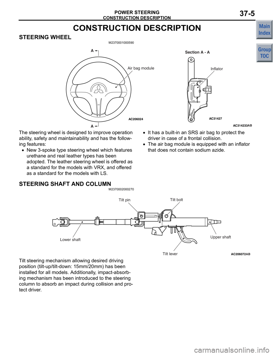
The steering wh
eel is de sig ned to impro v e operat ion
ability
, safety and main t a inabilit y and has the follow
-
ing features:
•New 3-spoke type stee ring whe e l which fe atures
uret
hane a nd real lea t her types has been
ado
pted. The leather stee ring wh eel is o f fere d as
a st
a ndard f o r the models with VRX, and of fered
as a st
an dard for the models with LS.
•It ha s a built-in a n SRS a i r ba g to pro t ect t he
driv
er in c a s e of a front a l c o ll is i o n.
•The air b ag mo dule is equip ped wit h an inflat or
tha
t does not cont ain sod i um azide.
STEERING SHAFT AND COLUMN
M23700020 0027 0
AC206072AB
Tilt bolt
Tilt pin
Lower shaft Tilt leverUpper shaft
T
i lt steering mecha n ism allowing desired d r iving
position
(tilt -up/tilt-down: 1 5 mm/20mm) ha s be en
inst
alled for all mo dels. Additiona lly , imp a ct-absorb
-
ing mechanism h a s be en in troduced to the steering
colu
mn t o absorb an imp a ct during collision an d pro
-
te c t dri v er .
Page 239 of 364
CONSTRUCTION DESCRIPTION
POWER STEERING37-6
IMPACT-ABSORBING MECHANISM
Primary collision
AC207724AB
Lower shaft ALower shaft B
After impact
Before impact
When a
vehicle is crashed a nd the lower shaf t is
loade
d from the g earbox side, the lower shaf t A is
forced
into the lower sha f t B t o absorb an imp a ct
load.
Thus, the steering column will not be projecte d
into t
he p a ssenge r comp artme n t to red u ce possible
chest in
jurie s .
SECONDARY COLLISION
AC207397AB
Upper shaft B
Before impact
After impact Upper shaft A
When th
e driver ’ s we ight is loaded to the stee ring
wh
eel a f ter air ba g deployment, the steerin g co lumn
sep
a ration mechanism built into the rot a tiona l a x is of
the upp
er-side tilt lever (t ilt b o lt) a nd the lower-side
tilt
fulcrum (t ilt p i n) move s the stee ring colu mn
assembly fo
rwa r d. The upper shaf t can also b e fur
-
ther retrac ted forward as sh own in the figure.
Page 240 of 364

ELECTRICAL POWER STEERING
POWER STEERING37-7
ELECTRICAL POWER STEERING
GENERAL INFORMATIONM2370000100862
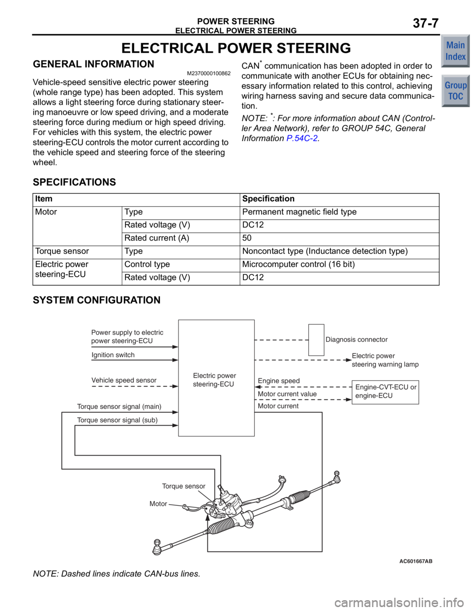
Vehicle-speed sensitive electric power steering
(whole range type) has been adopted. This system
allows a light steering force during stationary steer
-
ing manoeuvre or low speed driving, and a moderate
steering force during medium or high speed driving.
For vehicles with this system, the electric power
steering-ECU controls the motor current according to
the vehicle speed and steering force of the steering
wheel.
CAN* communication has been adopted in order to
communicate with another ECUs for obtaining nec
-
essary information related to this control, achieving
wiring harness saving and secure data communica
-
tion.
NOTE: *: For more information about CAN (Control-
ler Area Network), refer to GROUP 54C, General
Information
P.54C-2.
SPECIFICATIONS
ItemSpecification
MotorTy p ePermanent magnetic field type
Rated voltage (V)DC12
Rated current (A)50
Torque sensorTy p eNoncontact type (Inductance detection type)
Electric power
steering-ECUControl typeMicrocomputer control (16 bit)
Rated voltage (V)DC12
SYSTEM CONFIGURATION
AC601667AB
Electric power
steering-ECU
Ignition switch
Power supply to electric
power steering-ECU
Vehicle speed sensor
Motor Motor current value Engine speed
Torque sensor signal (main) Electric power
steering warning lamp
Diagnosis connector
Motor current
Torque sensor
Torque sensor signal (sub) Engine-CVT-ECU or
engine-ECU
NO
TE: Dash ed lines indicat e CAN-bu s lines.
Page 241 of 364

ELECTRICAL POWER STEERING
POWER STEERING37-8
ELECTRICAL PARTS AND FUNCTIONS
Parts nameDescription about function
SensorVehicle speed sensor (ABS-ECU)Sends the vehicle speed signal to the electric power
steering-ECU.
Torque sensorDetects a steering force, converts it into the voltage signal,
and then sends the signal to the electric power
steering-ECU.
ActuatorMotorGenerates assist torque by the steering operation to the
steering gear using the signals sent from the electric power
steering-ECU.
Electric power steering warning
lampWarns a driver of the system malfunction using the signal
sent from the electric power steering-ECU.
Electric power steering-ECUControl the actuator (motor) based on the signal sent from
sensor.
Controls the self-diagnostic fu nction and fail-safe function.
Controls diagnostic function (Compatible with M.U.T.-III).
GENERAL DESCRIPTION ON SYSTEM
AC207803
AC206444
AC206443
AB
Electric power
steering-ECU
Glove box
Torque sensor
Motor
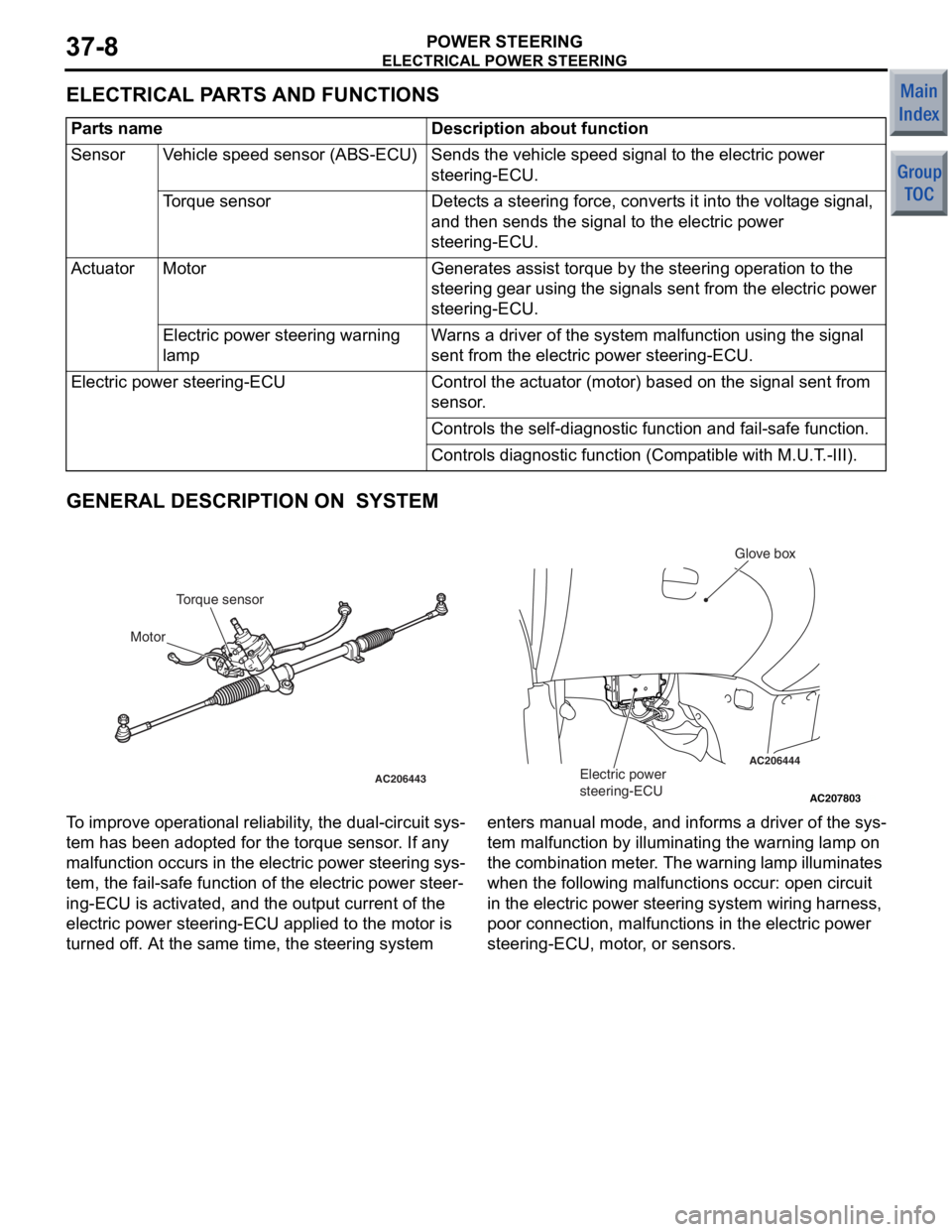
T o improve opera t iona l reliabi lity , th e dual-circuit sys-
tem ha s be en ad opted f o r the t o rque sensor . If a n y
malfunct
i on occurs in the electric power st eering sys
-
tem, the fail-sa f e fun c tio n of th e ele c tric power steer-
ing-ECU is activated, and the ou tput current of the
electric power steerin
g-ECU a pplied to the motor is
turned o
f f. At th e sa me time, the steerin g syste m enters man ual mode, and informs a dr iver of the sys
-
tem malfu
n ction by illuminating th e warnin g lamp on
the
comb in at io n me te r . Th e warn in g la mp il lu min a te s
wh
en the following malfu n ct ions occur: ope n circuit
in the
e l ectric power stee ring system wiring harness,
poor connectio
n , ma lfunction s in the e l ectric power
steering-ECU, mo
tor , or sensors.
Page 242 of 364
ELECTRICAL POWER STEERING
POWER STEERING37-9
STEERING GEAR
M2370003000239
AC208175
AC208174AC206443AC
NeutralSub
Torque sensor
Steered to leftMain
Steered to right
Output voltage (V)
Torque sensor characteristic chart
52.5
The torqu e sensor which detect s a opera t ed force of
the steerin
g wheel is inst alled in the stee ring g ear .
Whe
n th e st eer in g whe e l is tu rn ed , t h e ste e ring f o rce
is d
e tected by the to rque sensor . At the same time,
2-way supp
ly volt a ge signa l (main and sub ) are input
to the e
l ectric power steerin g-ECU.
MOT O RM237000 1 1 0003 6
AC208523
AC206443
AC207634
AB
View AMotor
Motor
View A
The mot
o r is inst alled in th e steering gea r . The ste e r-
ing motor is applied with a con t rol current sent from
the electric po
we r stee ring-ECU and genera t es t he
assist
torque to the steering ge ar according to the
steering op
eratio n.
Page 243 of 364

ELECTRICAL POWER STEERING
POWER STEERING37-10
ELECTRIC POWER STEERING-ECU
M2370000800106
AC207827AB
Glove box
Electric power
steering-ECU
The electric powe r stee ring-ECU is att a ch ed below
the glove
box, wh ich is integ r ated wit h an input inter
-
face circu i t, a microco m p u ter , an outp u t d r ive circuit,
a fail-sa
f e rela y , and a mot o r line relay et c.
It is also integrated with a self-diag nostic fu nction,
and illuminate
s the warn ing lamp an d set s d i agno sis
code
to the diagn osis connector .
CAN COMMUNICATION
The electric powe r stee ring-ECU perfo rms the da t a
transf
e r with a nother ECUs through CAN communi
-
cation.
SignalReceiver ECU
Engine-CVT-ECU or
engine-ECUMeter and A/C-ECU
Motor current signal•−
Electric power steering warning lamp request signal−•
NOTE: • ind i ca tes items which sends and re ceives
dat
a throu gh CAN communicat i on.
FA IL - SAFE FUNCTION
If the e l ectric power st eering - ECU de tect s any mal-
functi on, it illuminat es th e warnin g lamp, de activate s
the electric po
we r stee ring f unct i on, a nd the n
switches
the steerin g system in to ma nual mode .
DIAGNOSTIC FUNCTION
Electric po wer ste e ring -ECU has the following fu nc-
tions for easie r system ch ecks.
•Diagnosis code set
•Service dat a outp u t
All the above ite m s can be diagnosed using
M.U.T
. -III.
DIAGNOSIS CODE SET
There a r e 22 d i agno stic ite m s. Since all the d i agn os-
tic result s are recorded in volatile memory (EEP-
ROM*), they a r e sto r ed in the memo ry even th ough
the bat
tery t e rminals are d i sconne cted.
NOTE: .
•*: EEPROM (E lectrical Erasable & Programma-
ble ROM) Special ty pe o f me mory that can b e
prog
rammed or erase d ele c trically .
•For each diag nostic item, refer to the Mainte-
nance Manua l.
SERV ICE DA T A OUTPUT
Usin g M. U. T . -II I , t h e i n p u t d a t a s e n t f r om t h e se ns ors
and motors can
be rea d .
NOTE: For e a ch service dat a it em, re fer to th e Ma in-
tenance Manual.
Page 244 of 364

ELECTRICAL POWER STEERING
POWER STEERING37-11
OPERATION
M2370000700110
IGNITION SWITCH ON
Ignition supply voltage is applied to the electric
power steering-ECU, and the ECU enters standby
mode.
IGNITION SWITCH ON
AC601668AC207635 AB
Electric power
steering-ECU
OFF
OFF MotorMotor current signal
Maximum limit value (50A)
Engine speed
Engine speed
ON
500 r/min or 15 km/h
max 0.5s 0.7s
Motor output Determination of motor
control start Temporary increase of motor
assist limit value
Engine-CVT-ECU or
engine-ECU
1.
Whe n th e e ngine is st arted, the en gine sp eed sig-
nal sent from the en gine -CVT -ECU or
eng
ine-ECU is inp u t to th e ele c tric power steer
-
ing-ECU.
2. Af ter st a r ting the engine, the electric power ste e r-
ing-ECU judges the engin e st atu s "ENGINE
SPEED ON"
when the engine speed reaches 500
r/min or
the vehicle speed reaches 1 5 km/h or
more, the
n the p o wer assist functio n is ready .
STEERING WHEEL OPERAT ION
AC400096
AC206443AB
Electric power
steering-ECU
Torque
sensor
Torque sensor
Motor Motor
Motor current
Torque sensor signal (main)
Torque sensor signal (sub)
F A IL- S AFE FUNCTION OPERA T ION
Duri ng t h e f a il -s af e m o d e , t h e el ect r ic powe r st ee rin g
operate
s as a manual ste e ring system.