2006 MERCEDES-BENZ SPRINTER do not park after operating
[x] Cancel search: do not park after operatingPage 431 of 2305

3.3.4 HANDLING NO TROUBLE CODE
PROBLEMS
After reading Section 3.0 (System Description
and Functional Operation), you should have a bet-
ter understanding of the theory and operation of the
on-board diagnostics and how this relates to the
diagnosis of a vehicle that may have a driveability-
related symptom or complaint. When there are no
trouble codes present, refer to the no trouble code
(*) tests.
3.4 USING THE DRBIIIT
Refer to the DRBIIItuser 's guide for instructions
and assistance with reading the DTCs, erasing the
DTCs, lab scope usage and other DRBIIItfunc-
tions.
3.4.1 DRBIIITDOES NOT POWER UP
If the LEDs do not light or no sound is emitted at
start up, check for loose cable connections or a bad
cable. Check the vehicle battery voltage at data link
connector cavity 16. A minimum of 11.0 volts is
required to adequately power the DRBIIIt. Check
for proper ground connection at data link connector
cavities 4 and 5.
If all connections are proper between the
DRBIIItand the vehicle or other devices, and the
vehicle battery is fully charged, an inoperative
DRBIIItmay be the result of a faulty cable or
vehicle wiring. For a blank screen, refer to the
appropriate diagnostic manual.
3.4.2 DISPLAY IS NOT VISIBLE
Low temperatures will affect the visibility of the
display. Adjust the contrast to compensate for this
condition.
4.0 DISCLAIMERS, SAFETY,
WARNINGS
4.1 DISCLAIMERS
All information, illustrations and specifications
contained in this manual are based on the latest
information available at the time of publication.
The right is reserved to make changes at any time
without notice.
4.2 SAFETY
4.2.1 TECHNICIAN SAFETY INFORMATION
WARNING: HIGH-PRESSURE FUEL LINES
DELIVER DIESEL FUEL UNDER EXTREME
PRESSURE FROM THE INJECTION PUMP TO
THE FUEL INJECTORS. THIS MAY BE AS
HIGH AS 23,200 PSI (1600 BAR). USE
EXTREME CAUTION WHEN INSPECTING
FOR HIGH-PRESSURE FUEL LEAKS. FUEL
UNDER THIS AMOUNT OF PRESSURE CAN
PENETRATE SKIN CAUSING PERSONAL
INJURY OR DEATH. INSPECT FOR
HIGH-PRESSURE FUEL LEAKS WITH A
SHEET OF CARDBOARD. WEAR SAFETY
GOGGLES AND ADEQUATE PROTECTIVE
CLOTHING WHEN SERVICING FUEL
SYSTEM.
WARNING: ENGINES PRODUCE CARBON
MONOXIDE THAT IS ODORLESS, CAUSES
SLOWER REACTION TIME AND CAN LEAD
TO SERIOUS INJURY. WHEN THE ENGINE IS
OPERATING, KEEP SERVICE AREA WELL
VENTILATED OR ATTACH THE VEHICLE
EXHAUST SYSTEM TO THE SHOP EXHAUST
REMOVAL SYSTEM.
Set the parking brake and block the wheels before
testing or repairing the vehicle. It is especially
important to block the wheels on front wheel drive
vehicles; the parking brake does not hold the drive
wheels.
When servicing a vehicle, always wear eye pro-
tection and remove any metal jewelry such as
watchbands or bracelets that might make electrical
contact.
When diagnosing powertrain system problems, it
is important to follow approved procedures where
applicable. These procedures can be found in the
8
GENERAL INFORMATION
Page 862 of 2305

²Position of selector lever.
²Selected shift range.
²CAN signals.
²Engine Status.
Engine speed limits may be reached in all gears
with full throttle or in kick-down operation. In for-
ward driving, the shift range of the forward gears
can be adjusted by the operator by tipping the selec-
tor lever to the left or right (AutoStick). However, the
TCM features a downshift inhibitor to prevent the
engine from overspeeding.
OPERATION
The transmission control module (TCM) deter-
mines the current operating conditions of the vehicle
and controls the shifting process for shift comfort and
driving situations. It receives this operating data
from sensors and broadcast messages from other
modules.
The TCM uses inputs from several sensors that are
directly hardwired to the controller and it uses sev-
eral indirect inputs that are used to control shifts.
This information is used to actuate the proper sole-
noids in the valve body to achieve the desired gear.
The shift lever assembly (SLA) has several items
that are monitored by the TCM to calculate shift
lever position. The reverse light switch, an integral
part of the SLA, controls the reverse light relay con-
trol circuit. The Brake/Transmission Shift Interlock
(BTSI) solenoid and the park lockout solenoid (also
part of the SLA) are controlled by the TCM.
The ECM and ABS broadcast messages over the
controller area network (CAN C) bus for use by the
TCM. The TCM uses this information, with other
inputs, to determine the transmission operating con-
ditions.
The TCM:
²determines the momentary operating conditions
of the vehicle.
²controls all shift processes.
²considers shift comfort and the driving situation.
The TCM controls the solenoid valves for modulat-
ing shift pressures and gear changes. Relative to the
torque being transmitted, the required pressures are
calculated from load conditions, engine rpm, vehicle
speed, and ATF temperature.
The following functions are contained in the TCM:
²Shift Program
²Downshift Safety
²Torque Converter Lock-Up Clutch.
²Adaptation.
This transmission does not have a TCM relay.
Power is supplied to the SLA and the TCM directly
from the ignition.
The TCM continuously checks for electrical prob-
lems, mechanical problems, and some hydraulic prob-
lems. When a problem is sensed, the TCM stores a
diagnostic trouble code (DTC). Some of these codescause the transmission to go into ªLimp-Inº or
ªdefaultº mode. Some DTCs cause permanent
Limp-In and others cause temporary Limp-In. The
NAG1 defaults in the current gear position if a DTC
is detected, then after a key cycle the transmission
will go into Limp-in, which is mechanical 2nd gear.
Some DTCs may allow the transmission to resume
normal operation (recover) if the detected problem
goes away. A permanent Limp-In DTC will recover
when the key is cycled, but if the same DTC is
detected for three key cycles the system will not
recover and the DTC must be cleared from the TCM
with the DRBIIItscan tool.
TCM SIGNALS
The TCM registers one part of the input signals by
direct inputs, the other part by CAN C bus. In addi-
tion to the direct control of the actuators, the TCM
sends various output signals by CAN C bus to other
control modules.
Selector Lever Position
The TCM monitors the SLA for all shift lever posi-
tions via the CAN bus.
ATF Temperature Sensor
The ATF temperature sensor is a positive temper-
ature co-efficient (PTC) thermistor. It measures the
temperature of the transmission fluid and is a direct
input signal for the TCM. The temperature of the
ATF has an influence on the shifttime and resulting
shift quality. As the temperature rises, resistance
rises, and therefore, the probing voltage is decreas-
ing. Because of its registration, the shifting process
can be optimized in all temperature ranges.
The ATF temperature sensor is wired in series
with the park/neutral contact. The temperature sig-
nal is transmitted to the TCM only when the reed
contact of the park/neutral contact is closed because
the TCM only reads ATF temperature while in any
forward gear, or REVERSE. When the transmission
is in PARK or NEUTRAL, the TCM will substitute
the engine temperature for the ATF temperature.
Starter Interlock
The TCM monitors a contact switch wired in series
with the transmission temperature sensor to deter-
mine PARK and NEUTRAL positions. The contact
switch is open in PARK and NEUTRAL. The TCM
senses transmission temperature as high (switch
supply voltage), confirming switch status as open.
The TCM then broadcasts a message over CAN bus
to confirm switch status. The PCM receives this
information and allows operation of the starter cir-
cuit.
VAELECTRONIC CONTROL MODULES 8E - 7
Page 929 of 2305

Light Emitting Diode (LED) behind the cutout in the
opaque layer of the overlay causes the icon to appear
silhouetted against an amber field through the trans-
lucent outer layer of the overlay when the indicator
is illuminated from behind by the LED, which is sol-
dered onto the instrument cluster electronic circuit
board. The ABS indicator is serviced as a unit with
the instrument cluster.
OPERATION
The ABS indicator gives an indication to the vehi-
cle operator when the ABS or the electronic brake
force distribution (EBV) systems are faulty or inoper-
ative. This indicator is controlled by a transistor on
the instrument cluster circuit board based upon clus-
ter programming and electronic messages received by
the cluster from the Controller Antilock Brake (CAB)
over the Controller Area Network (CAN) data bus.
The ABS indicator Light Emitting Diode (LED) is
completely controlled by the instrument cluster logic
circuit, and that logic will only allow this indicator to
operate when the instrument cluster detects that the
ignition switch is in the On position. Therefore, the
LED will always be off when the ignition switch is in
any position except On. The LED only illuminates
when it is provided a path to ground by the instru-
ment cluster transistor. The instrument cluster will
turn on the ABS indicator for the following reasons:
²Bulb Test- Each time the ignition switch is
turned to the On position the ABS indicator is illu-
minated by the cluster for about two seconds as a
bulb test.
²ABS Lamp-On Message- Each time the clus-
ter receives a lamp-on message from the CAB, the
ABS indicator will be illuminated. The indicator
remains illuminated until the cluster receives a
lamp-off message from the CAB, or until the ignition
switch is turned to the Off position, whichever occurs
first.
The CAB continually monitors the ABS and EBV
circuits and sensors to decide whether the systems
are in good operating condition. The CAB then sends
the proper lamp-on or lamp-off messages to the
instrument cluster. If the CAB sends a lamp-on mes-
sage after the bulb test, it indicates that the CAB
has detected a system malfunction and/or that the
ABS or EBV systems have become inoperative. The
CAB will store a Diagnostic Trouble Code (DTC) for
any malfunction it detects. For proper diagnosis of
the ABS and EBV systems, the CAB, the CAN data
bus, the electronic message inputs to the instrument
cluster, or the instrument cluster circuitry that con-
trols the ABS indicator, a diagnostic scan tool is
required. Refer to the appropriate diagnostic infor-
mation.
ADR INDICATOR
DESCRIPTION
A constant engine speed (ADR) indicator is stan-
dard equipment on all instrument clusters, but is
only functional on vehicles equipped with the
optional ADR switch. The ADR indicator is located
near the lower edge of the instrument cluster, to the
right of the multi-function indicator display. The
ADR indicator consists of the text ªADRº imprinted
within a rectangular cutout in the opaque layer of
the instrument cluster overlay. The dark outer layer
of the overlay prevents the indicator from being
clearly visible when it is not illuminated. An amber
Light Emitting Diode (LED) behind the cutout in the
opaque layer of the overlay causes the text to appear
silhouetted against an amber field through the trans-
lucent outer layer of the overlay when the indicator
is illuminated from behind by the LED, which is sol-
dered onto the instrument cluster electronic circuit
board. The ADR indicator is serviced as a unit with
the instrument cluster.
OPERATION
The constant engine speed (ADR) indicator gives
an indication to the vehicle operator concerning the
operating status of the constant engine speed (ADR)
feature. The ADR indicator is controlled by a transis-
tor on the instrument cluster circuit board based
upon cluster programming and electronic messages
received by the cluster from the Engine Control Mod-
ule (ECM) over the Controller Area Network (CAN)
data bus. The ADR indicator Light Emitting Diode
(LED) is completely controlled by the instrument
cluster logic circuit, and that logic will only allow
this indicator to operate when the instrument cluster
detects that the ignition switch is in the On position.
Therefore, the LED will always be off when the igni-
tion switch is in any position except On. The LED
only illuminates when it is provided a path to ground
by the instrument cluster transistor. The instrument
cluster will turn on the traction control indicator for
the following reasons:
²Constant Engine Speed (ADR) Indicator
Lamp-On Message- Each time the cluster receives
an ADR indicator lamp-on message from the ECM,
the indicator will be illuminated. The indicator is
illuminated when the ADR feature has been acti-
vated with the ADR switch, and is turned off when
the ADR feature is deactivated with the ADR switch.
The ADR indicator will be extinguished if the ADR
feature is turned off because the park brake has been
released or the vehicle is in motion. The ADR indica-
tor will also be extinguished if the service brake
pedal is depressed, but the ADR feature will auto-
matically be restored and the indicator illuminated
when the brake pedal is released. The indicator
8J - 10 INSTRUMENT CLUSTERVA
Page 930 of 2305

remains illuminated until the cluster receives a
lamp-off message from the ECM, or until the ignition
switch is turned to the Off position, whichever occurs
first.
The ECM continually monitors the constant engine
speed (ADR) switch and electronic messages from the
Controller Antilock Brake (CAB) concerning the sta-
tus of the four wheel speed sensors, the park brake
switch and the brake lamp switch to determine the
correct operating mode for the ADR feature. The
ECM then sends the proper lamp-on or lamp-off mes-
sages to the instrument cluster. See the owner's man-
ual in the vehicle glove box for more information on
the features, use, activation and deactivation of the
constant engine speed (ADR) feature. For proper
diagnosis of the ADR feature, the ECM, the CAB, the
CAN data bus, or the electronic message inputs to
the instrument cluster that control the ADR indica-
tor, a diagnostic scan tool is required. Refer to the
appropriate diagnostic information.
AIRBAG INDICATOR
DESCRIPTION
An airbag indicator is standard equipment on all
instrument clusters. The airbag indicator is located
near the left edge of the instrument cluster, next to
the tachometer. The airbag indicator consists of a
stencil-like cutout of the letters ªSRSº in the opaque
layer of the instrument cluster overlay. The dark
outer layer of the overlay prevents the indicator from
being clearly visible when it is not illuminated. A red
Light Emitting Diode (LED) behind the cutout in the
opaque layer of the overlay causes the ªSRSº text to
appear in red through the translucent outer layer of
the overlay when the indicator is illuminated from
behind by the LED, which is soldered onto the
instrument cluster electronic circuit board. The air-
bag indicator is serviced as a unit with the instru-
ment cluster.
OPERATION
The airbag (SRS) indicator gives an indication to
the vehicle operator when the Airbag Control Module
(ACM) has recorded a Diagnostic Trouble Code (DTC)
for a Supplemental Restraint System (SRS) circuit or
component malfunction. Such a DTC may indicate
that the SRS is faulty or inoperative. The airbag
indicator is controlled by a transistor on the instru-
ment cluster circuit board based upon cluster pro-
gramming and a hard wired input received by the
cluster from the ACM. The airbag indicator Light
Emitting Diode (LED) is completely controlled by the
instrument cluster logic circuit, and that logic will
only allow this indicator to operate when the instru-
ment cluster detects that the ignition switch is in the
On position. Therefore, the LED will always be offwhen the ignition switch is in any position except
On. The LED only illuminates when it is provided a
path to ground by the instrument cluster transistor.
The instrument cluster will turn on the airbag indi-
cator for the following reasons:
²Bulb Test- Each time the ignition switch is
turned to the On position the airbag indicator is illu-
minated for about four seconds. The entire four sec-
ond bulb test is a function of the ACM.
²Airbag Lamp-On Input- Each time the cluster
receives a lamp-on input from the ACM, the airbag
indicator will be illuminated. The indicator can be
flashed on and off, or illuminated solid, as dictated
by the ACM input. For some DTC's, if the problem
does not recur, the ACM will send a lamp-off input
automatically. Other DTC's may require that a fault
be repaired and the ACM be reset before a lamp-off
input will be sent. For more information on the ACM
and the DTC set and reset parameters, refer to 8 -
ELECTRICAL/RESTRAINTS/AIRBAG CONTROL
MODULE - OPERATION). The indicator remains
illuminated until the cluster receives a lamp-off
input from the ACM, or until the ignition switch is
turned to the Off position, whichever occurs first.
²Airbag Indicator Malfunction- Following the
seatbelt reminder function, each time the cluster
detects a malfunction in the airbag (SRS) indicator or
the airbag indicator circuit, the cluster will flash the
seatbelt indicator on and off. The cluster will con-
tinue to flash the seatbelt indicator until the airbag
indicator circuit fault is resolved, or until the ignition
switch is turned to the Off position, whichever occurs
first.
The ACM continually monitors the SRS circuits
and sensors to decide whether the system is in good
operating condition. The ACM then provides the
proper lamp-on or lamp-off inputs to the instrument
cluster. If the ACM provides a lamp-on input after
the bulb test, it indicates that the ACM has detected
a system malfunction and/or that the airbags and
seat belt tensioners may not deploy when required,
or may deploy when not required. The ACM will
store a DTC for any malfunction it detects. The ACM
input circuit to the instrument cluster can be diag-
nosed using conventional diagnostic tools and meth-
ods. For proper diagnosis of the SRS, the ACM, or
the instrument cluster circuitry that controls the air-
bag indicator, a diagnostic scan tool is required. Refer
to the appropriate diagnostic information.
AMBIENT TEMPERATURE
INDICATOR
DESCRIPTION
An ambient temperature indicator is optional
equipment on all instrument clusters. In vehicles so
VAINSTRUMENT CLUSTER 8J - 11
Page 941 of 2305

The ECM continually monitors the fuel and emis-
sions system circuits and sensors to decide whether
the system is in good operating condition. The ECM
then sends the proper lamp-on or lamp-off messages
to the instrument cluster. If the instrument cluster
turns on the MIL after the bulb test, it may indicate
that a malfunction has occurred and that the fuel
and emissions systems may require service. For
proper diagnosis of the fuel and emissions systems,
the ECM, the CAN data bus, or the electronic mes-
sage inputs to the instrument cluster that control the
MIL, a diagnostic scan tool is required. Refer to the
appropriate diagnostic information.
MULTI - FUNCTION INDICA-
TOR
DESCRIPTION
A multi-function indicator is standard equipment
on all instrument clusters. The multi-function indica-
tor is located near the lower edge of the instrument
cluster, directly below the speedometer. The multi-
function indicator consists of a Liquid Crystal Dis-
play (LCD) unit and four push button-controlled
switches that are soldered onto the instrument clus-
ter electronic circuit board. The LCD is visible
through a large rectangular cutout in the instrument
cluster overlay, while the four switch push buttons
extend through a black plastic switch bezel located
on the cluster lens directly below the LCD. The four
multi-function indicator push buttons allow the vehi-
cle operator to configure and adjust several of the
display features. The buttons are labeled from left to
right: ªmiº (miles) or ªkmº (kilometers), an icon
depicting an analog clock face (clock), ª2º (minus),
and ª+º (plus).
The multi-function indicator LCD displays both
alpha-numeric characters and numerous icons to pro-
vide information to the vehicle operator. The indica-
tions of the multi-function indicator are not visible
when the LCD is not illuminated. When illuminated
the indications appear as dark characters and icons
silhouetted against an amber field. When the exterior
lighting is turned Off, the display is illuminated at
maximum brightness. When the exterior lighting is
turned On the display illumination level can be
adjusted in concert with the cluster general illumina-
tion lighting using the ª+º (plus) and ª2º (minus)
multi-function indicator push buttons. The multi-
function indicator LCD unit and push button
switches are serviced as a unit with the instrument
cluster.
OPERATION
The multi-function indicator has several display
capabilities including odometer, trip odometer, clock,engine oil level data, gear selector indicator
(PRNDL), certain diagnostic information and, on
vehicles so equipped, an optional Active Service SYS-
Tem (ASSYST) engine oil maintenance indicator and
an optional outside ambient temperature indicator.
The multi-function indicator is completely controlled
by the instrument cluster logic circuit, and that logic
will allow this indication to be viewed whenever the
multi-function indicator Liquid Crystal Display
(LCD) is activated. Therefore, the indicator remains
functional regardless of the ignition switch position.
With the ignition switch in the Off or Accessory posi-
tions and the key removed from the ignition lock cyl-
inder, the display is activated when the park lamps
are turned On or, for about thirty seconds after any
one of the multi-function indicator switch push but-
tons is depressed. Otherwise, the display unit is
active for about thirty seconds after the key is
inserted into the ignition lock cylinder, and inactive
about thirty seconds after the key is removed from
the ignition lock cylinder.
The multi-function indicator ªmiº (miles) or
ªkmº(kilometers) switch push button is used to con-
trol the odometer/trip odometer display modes. The
multi-function indicator clock switch push button is
used to control the clock/outside temperature display
modes. The multi-function indicator ª+º (plus) and
ª2º (minus) switch push buttons are used to adjust
the cluster general illumination dimming level, the
clock, and other cluster settings. See the owner's
manual in the vehicle glove box for more information
on the features, use, operation and setting proce-
dures for the various standard and optional multi-
function indicator displays.
Proper testing of the multi-function indicator LCD
unit, the CAN data bus and the electronic data bus
message inputs to the instrument cluster that control
some of the multi-function indicator functions
requires the use of a diagnostic scan tool. Refer to
the appropriate diagnostic information. Additional
details for the odometer/trip odometer, the clock, the
gear selector indicator, the ambient temperature indi-
cator and the ASSYST warning and reminder func-
tions of the multi-function indicator may be found
elsewhere in this service information.
ODOMETER
DESCRIPTION
An odometer and trip odometer are standard
equipment in all instrument clusters. The odometer
and trip odometer values are displayed on the left
side of the multi-function indicator Liquid Crystal
Display (LCD). The LCD is soldered onto the cluster
electronic circuit board and is visible through a win-
dow with a clear lens located near the lower edge of
8J - 22 INSTRUMENT CLUSTERVA
Page 1047 of 2305
other minor debris from the outside windshield glass
surface that might be encountered while driving the
vehicle under numerous types of inclement operating
conditions.
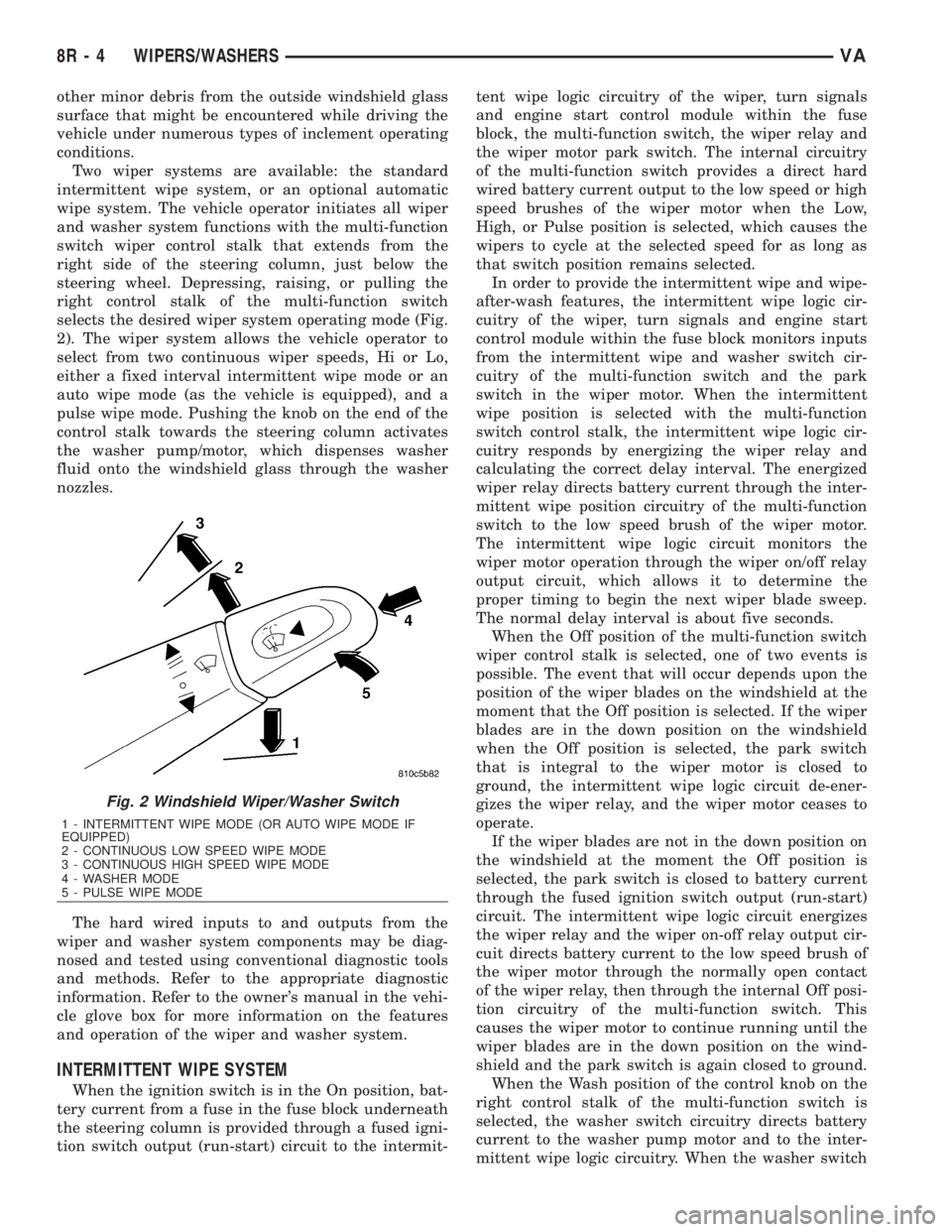
Two wiper systems are available: the standard
intermittent wipe system, or an optional automatic
wipe system. The vehicle operator initiates all wiper
and washer system functions with the multi-function
switch wiper control stalk that extends from the
right side of the steering column, just below the
steering wheel. Depressing, raising, or pulling the
right control stalk of the multi-function switch
selects the desired wiper system operating mode (Fig.
2). The wiper system allows the vehicle operator to
select from two continuous wiper speeds, Hi or Lo,
either a fixed interval intermittent wipe mode or an
auto wipe mode (as the vehicle is equipped), and a
pulse wipe mode. Pushing the knob on the end of the
control stalk towards the steering column activates
the washer pump/motor, which dispenses washer
fluid onto the windshield glass through the washer
nozzles.
The hard wired inputs to and outputs from the
wiper and washer system components may be diag-
nosed and tested using conventional diagnostic tools
and methods. Refer to the appropriate diagnostic
information. Refer to the owner's manual in the vehi-
cle glove box for more information on the features
and operation of the wiper and washer system.
INTERMITTENT WIPE SYSTEM
When the ignition switch is in the On position, bat-
tery current from a fuse in the fuse block underneath
the steering column is provided through a fused igni-
tion switch output (run-start) circuit to the intermit-tent wipe logic circuitry of the wiper, turn signals
and engine start control module within the fuse
block, the multi-function switch, the wiper relay and
the wiper motor park switch. The internal circuitry
of the multi-function switch provides a direct hard
wired battery current output to the low speed or high
speed brushes of the wiper motor when the Low,
High, or Pulse position is selected, which causes the
wipers to cycle at the selected speed for as long as
that switch position remains selected.
In order to provide the intermittent wipe and wipe-
after-wash features, the intermittent wipe logic cir-
cuitry of the wiper, turn signals and engine start
control module within the fuse block monitors inputs
from the intermittent wipe and washer switch cir-
cuitry of the multi-function switch and the park
switch in the wiper motor. When the intermittent
wipe position is selected with the multi-function
switch control stalk, the intermittent wipe logic cir-
cuitry responds by energizing the wiper relay and
calculating the correct delay interval. The energized
wiper relay directs battery current through the inter-
mittent wipe position circuitry of the multi-function
switch to the low speed brush of the wiper motor.
The intermittent wipe logic circuit monitors the
wiper motor operation through the wiper on/off relay
output circuit, which allows it to determine the
proper timing to begin the next wiper blade sweep.
The normal delay interval is about five seconds.
When the Off position of the multi-function switch
wiper control stalk is selected, one of two events is
possible. The event that will occur depends upon the
position of the wiper blades on the windshield at the
moment that the Off position is selected. If the wiper
blades are in the down position on the windshield
when the Off position is selected, the park switch
that is integral to the wiper motor is closed to
ground, the intermittent wipe logic circuit de-ener-
gizes the wiper relay, and the wiper motor ceases to
operate.
If the wiper blades are not in the down position on
the windshield at the moment the Off position is
selected, the park switch is closed to battery current
through the fused ignition switch output (run-start)
circuit. The intermittent wipe logic circuit energizes
the wiper relay and the wiper on-off relay output cir-
cuit directs battery current to the low speed brush of
the wiper motor through the normally open contact
of the wiper relay, then through the internal Off posi-
tion circuitry of the multi-function switch. This
causes the wiper motor to continue running until the
wiper blades are in the down position on the wind-
shield and the park switch is again closed to ground.
When the Wash position of the control knob on the
right control stalk of the multi-function switch is
selected, the washer switch circuitry directs battery
current to the washer pump motor and to the inter-
mittent wipe logic circuitry. When the washer switch
Fig. 2 Windshield Wiper/Washer Switch
1 - INTERMITTENT WIPE MODE (OR AUTO WIPE MODE IF
EQUIPPED)
2 - CONTINUOUS LOW SPEED WIPE MODE
3 - CONTINUOUS HIGH SPEED WIPE MODE
4 - WASHER MODE
5 - PULSE WIPE MODE
8R - 4 WIPERS/WASHERSVA
Page 1048 of 2305
is closed with the wiper system turned Off, the inter-
mittent wipe logic circuitry operates the wiper motor
in the same manner as it does to provide the inter-
mittent wipe mode operation. After the state of the
washer switch changes to open, the intermittent wipe
logic circuitry monitors the wiper motor through the
wiper on-off relay output circuit, which allows it to
monitor the number of wiper blade sweeps. After the
appropriate number of wiper sweeps the intermittent
wipe logic circuitry operates the wiper motor to
return the wipers to their park position, then de-en-
ergizes the wiper relay.
AUTOMATIC WIPE SYSTEM
When the ignition switch is in the On position, bat-
tery current from a fuse in the fuse block underneath
the steering column is provided through a fused igni-
tion switch output (run-start) circuit to the rain sen-
sor control module under the instrument panel, to
the rain sensor within the base of the inside rear
view mirror on the windshield, and to the multi-func-
tion switch. The internal circuitry of the multi-func-
tion switch provides direct hard wired battery
current outputs to the rain sensor control module to
indicate the selected wiper operating mode. The con-
trol module logic monitors the inputs from the multi-
function switch as well as from the rain sensor and
the wiper motor park switch in order to provide the
outputs necessary to operate the wiper motor and the
washer pump motor as requested.
When the automatic wipe position is selected with
the multi-function switch control stalk, the rain sen-
sor control module logic circuitry responds by provid-
ing an acknowledgment sweep of the wipers. The
rain sensor calculates the correct wiper speed and
wiper sweep intervals required to remove the mois-
ture detected on the windshield glass and provides
this input to the rain sensor control module. The con-
trol module then energizes and de-energizes the
wiper motor automatically. The automatic wipe logic
will also provide a wipe-after-wash feature to clear
washer fluid that is directed onto the windshield
when the washer system is utilized.
When the Off position of the multi-function switch
wiper control stalk is selected, one of two events is
possible. The event that will occur depends upon the
position of the wiper blades on the windshield at the
moment that the Off position is selected. If the wiper
blades are in the down position on the windshield
when the Off position is selected, the park switch
that is integral to the wiper motor is closed to
ground, and the rain sensor control module logic cir-
cuit de-energizes the wiper motor. If the wiper blades
are not in the down position at the moment the Off
position is selected, the park switch is an open cir-
cuit. The control module logic circuit directs battery
current to the low speed brush of the wiper motor,
which causes the wiper motor to continue runninguntil the wiper blades are in the down position on
the windshield and the park switch is again closed to
ground.
When the Wash position of the control knob on the
right control stalk of the multi-function switch is
selected with the wiper system turned Off, the rain
sensor control module logic circuitry operates the
wiper motor in the same manner as it does to provide
the automatic wipe mode operation. After the state of
the washer switch changes to open the control mod-
ule monitors the wiper motor through the wiper park
switch sense circuit, which allows it to monitor the
number of wiper blade sweeps. After the appropriate
number of wiper sweeps the control module operates
the wiper motor to return the wipers to their park
position, then de-energizes the wiper motor.
OPERATING MODES
The components of the wiper and washer system
are designed to provide the following operating
modes:
²Automatic Wipe Mode- On vehicles so
equipped, the internal circuitry of the multi-function
switch, the rain sensor control module and the rain
sensor work in concert to provide wiper system oper-
ation automatically whenever moisture is detected on
the windshield glass.
²Continuous Wipe Mode- The two-speed wiper
motor, the internal circuitry of the multi-function
switch, and the wiper system logic circuits work in
concert to provide two continuous wipe cycles, low
speed or high speed.
²Intermittent Wipe Mode- On vehicles so
equipped, the internal circuitry of the multi-function
switch, the intermittent wipe circuitry of the wiper,
turn signals and engine start control module in the
fuse block, and the wiper relay work in concert to
provide an intermittent wipe mode with a single,
fixed delay interval.
²Pulse Wipe Mode- The internal circuitry of
the multi-function switch and the wiper system logic
circuits work in concert to provide a pulse wipe mode
that will allow the wiper motor to be operated for a
single, complete wipe cycle.
²Washer Mode- When the washer system is
activated with the multi-function switch while the
wiper system is operating, washer fluid will be dis-
pensed onto the windshield glass through the washer
nozzles for as long as the washer pump/motor is
energized.
²Wipe-After-Wash Mode- The wiper system
logic circuitry provides a wipe-after-wash feature. If
the wipers are turned Off, this feature will operate
the washer pump/motor and the wipers for as long as
the washer system is activated, then provide several
additional wipe cycles after the washer system is
deactivated before parking the wiper blades near the
base of the windshield.
VAWIPERS/WASHERS 8R - 5
Page 1050 of 2305
CONDITION POSSIBLE CAUSES CORRECTION
WIPERS INOPERATIVE IN
HIGH POSITION1. Faulty high speed circuit. 1. Test and repair the open high speed
circuit between the multi-function switch
and the wiper motor as required.
2. Faulty multi-function switch. 2. Test and replace the multi-function
switch as required.
3. Faulty wiper high speed brush. 3. Test and replace the wiper motor as
required.
WIPERS DO NOT PARK
AFTER OPERATING1. Faulty motor feed circuit. 1. Test and repair the open fused ignition
switch output circuit to the wiper motor as
required.
2. Faulty park switch output circuit. 2. Test and repair the open or shorted cir-
cuit between the wiper park switch and
the wiper relay as required.
3. Faulty wiper relay. 3. Test and replace the wiper relay as re-
quired.
4. Faulty park switch. 4. Test and replace the wiper motor as
required.
WASHERS INOPERATIVE 1. Faulty washer pump ground cir-
cuit.1. Test and repair the open ground circuit
as required.
2. Faulty washer pump feed circuit. 2. Test and repair the open circuit be-
tween the multi-function switch and the
washer pump as required.
3. Faulty washer pump motor. 3. Test and replace the washer pump as
required.
4. Faulty muli-function switch. 4. Test and replace the multi-function
switch as required.
AUTOMATIC WIPER SYSTEM
CONDITION POSSIBLE CAUSES CORRECTION
WIPERS INOPERATIVE IN
ALL SWITCH POSITIONS1. Faulty or missing fuse. 1. Test and replace the fuse as required.
2. Faulty wiper motor ground circuit. 2. Test and repair the open ground circuit
as required.
3. Faulty wiper motor. 3. Test and replace the wiper motor as
required.
4. Faulty multi-function switch feed
circuit.4. Test and repair the open fused ignition
switch output circuit between the fuse and
the multi-function switch as required.
5. Faulty multi-function switch. 5. Test and replace the multi-function
switch as required.
6. Faulty rain sensor control module
ground circuit.6. Test and repair the open ground circuit
as required.
7. Faulty rain sensor control module
feed circuit.7. Test and repair the open fused ignition
switch output circuit between the fuse and
the rain sensor control module as re-
quired.
8. Faulty rain sensor control mod-
ule.8. Test and replace the rain sensor control
module as required.
VAWIPERS/WASHERS 8R - 7