Page 65 of 2305
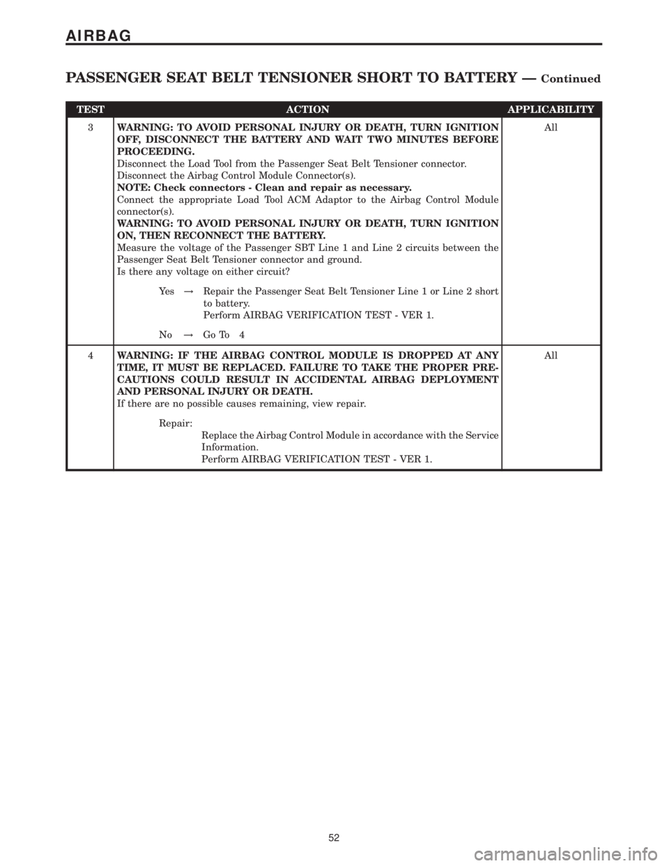
TEST ACTION APPLICABILITY
3WARNING: TO AVOID PERSONAL INJURY OR DEATH, TURN IGNITION
OFF, DISCONNECT THE BATTERY AND WAIT TWO MINUTES BEFORE
PROCEEDING.
Disconnect the Load Tool from the Passenger Seat Belt Tensioner connector.
Disconnect the Airbag Control Module Connector(s).
NOTE: Check connectors - Clean and repair as necessary.
Connect the appropriate Load Tool ACM Adaptor to the Airbag Control Module
connector(s).
WARNING: TO AVOID PERSONAL INJURY OR DEATH, TURN IGNITION
ON, THEN RECONNECT THE BATTERY.
Measure the voltage of the Passenger SBT Line 1 and Line 2 circuits between the
Passenger Seat Belt Tensioner connector and ground.
Is there any voltage on either circuit?All
Ye s!Repair the Passenger Seat Belt Tensioner Line 1 or Line 2 short
to battery.
Perform AIRBAG VERIFICATION TEST - VER 1.
No!Go To 4
4WARNING: IF THE AIRBAG CONTROL MODULE IS DROPPED AT ANY
TIME, IT MUST BE REPLACED. FAILURE TO TAKE THE PROPER PRE-
CAUTIONS COULD RESULT IN ACCIDENTAL AIRBAG DEPLOYMENT
AND PERSONAL INJURY OR DEATH.
If there are no possible causes remaining, view repair.All
Repair:
Replace the Airbag Control Module in accordance with the Service
Information.
Perform AIRBAG VERIFICATION TEST - VER 1.
52
AIRBAG
PASSENGER SEAT BELT TENSIONER SHORT TO BATTERY ÐContinued
Page 66 of 2305
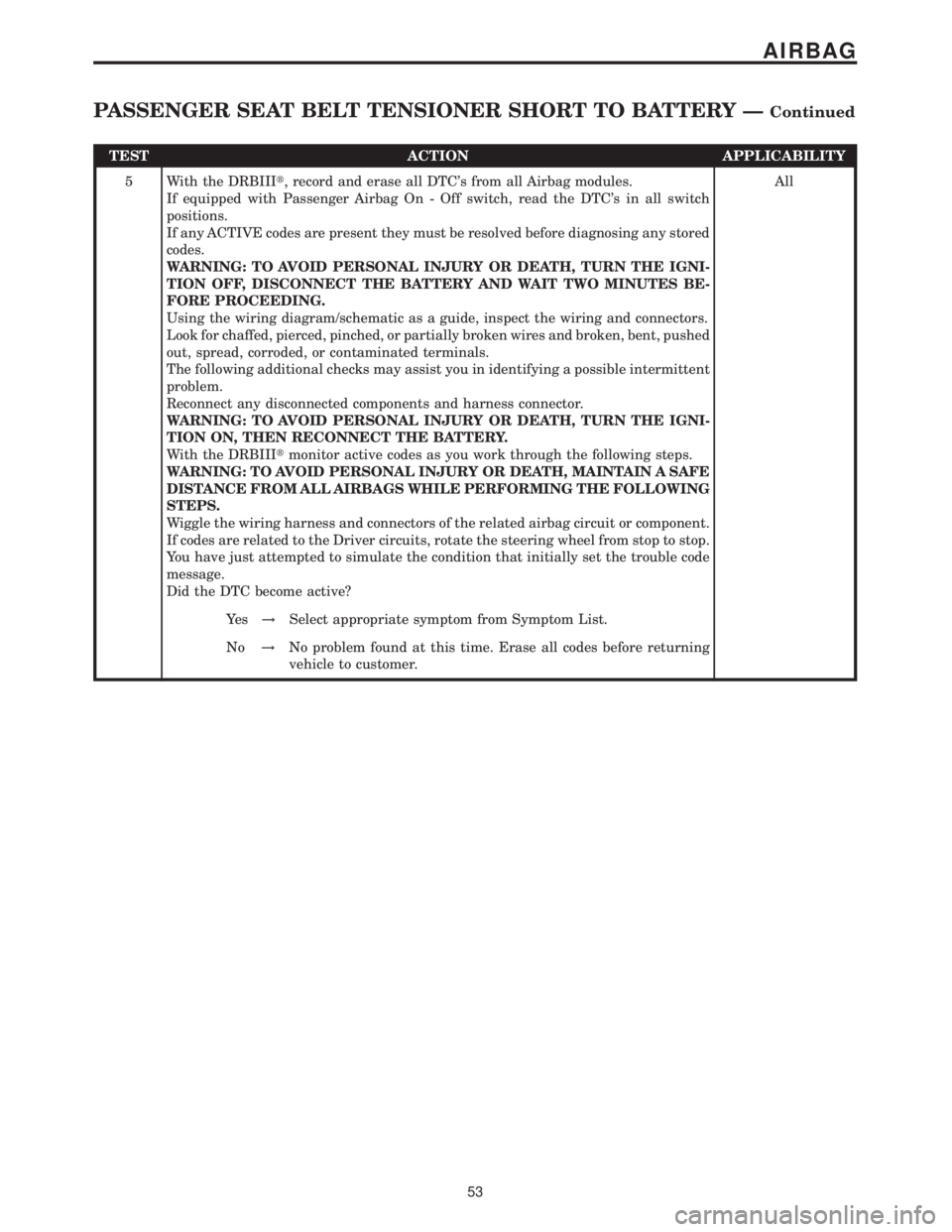
TEST ACTION APPLICABILITY
5 With the DRBIIIt, record and erase all DTC's from all Airbag modules.
If equipped with Passenger Airbag On - Off switch, read the DTC's in all switch
positions.
If any ACTIVE codes are present they must be resolved before diagnosing any stored
codes.
WARNING: TO AVOID PERSONAL INJURY OR DEATH, TURN THE IGNI-
TION OFF, DISCONNECT THE BATTERY AND WAIT TWO MINUTES BE-
FORE PROCEEDING.
Using the wiring diagram/schematic as a guide, inspect the wiring and connectors.
Look for chaffed, pierced, pinched, or partially broken wires and broken, bent, pushed
out, spread, corroded, or contaminated terminals.
The following additional checks may assist you in identifying a possible intermittent
problem.
Reconnect any disconnected components and harness connector.
WARNING: TO AVOID PERSONAL INJURY OR DEATH, TURN THE IGNI-
TION ON, THEN RECONNECT THE BATTERY.
With the DRBIIItmonitor active codes as you work through the following steps.
WARNING: TO AVOID PERSONAL INJURY OR DEATH, MAINTAIN A SAFE
DISTANCE FROM ALL AIRBAGS WHILE PERFORMING THE FOLLOWING
STEPS.
Wiggle the wiring harness and connectors of the related airbag circuit or component.
If codes are related to the Driver circuits, rotate the steering wheel from stop to stop.
You have just attempted to simulate the condition that initially set the trouble code
message.
Did the DTC become active?All
Ye s!Select appropriate symptom from Symptom List.
No!No problem found at this time. Erase all codes before returning
vehicle to customer.
53
AIRBAG
PASSENGER SEAT BELT TENSIONER SHORT TO BATTERY ÐContinued
Page 67 of 2305
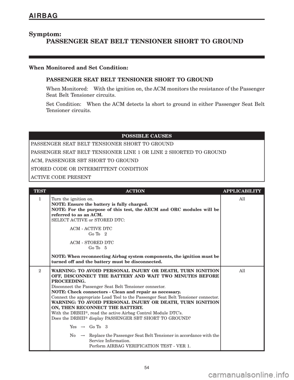
Symptom:
PASSENGER SEAT BELT TENSIONER SHORT TO GROUND
When Monitored and Set Condition:
PASSENGER SEAT BELT TENSIONER SHORT TO GROUND
When Monitored: With the ignition on, the ACM monitors the resistance of the Passenger
Seat Belt Tensioner circuits.
Set Condition: When the ACM detects la short to ground in either Passenger Seat Belt
Tensioner circuits.
POSSIBLE CAUSES
PASSENGER SEAT BELT TENSIONER SHORT TO GROUND
PASSENGER SEAT BELT TENSIONER LINE 1 OR LINE 2 SHORTED TO GROUND
ACM, PASSENGER SBT SHORT TO GROUND
STORED CODE OR INTERMITTENT CONDITION
ACTIVE CODE PRESENT
TEST ACTION APPLICABILITY
1 Turn the ignition on.
NOTE: Ensure the battery is fully charged.
NOTE: For the purpose of this test, the AECM and ORC modules will be
referred to as an ACM.
SELECT ACTIVE or STORED DTC:All
ACM - ACTIVE DTC
Go To 2
ACM - STORED DTC
Go To 5
NOTE: When reconnecting Airbag system components, the ignition must be
turned off and the battery must be disconnected.
2WARNING: TO AVOID PERSONAL INJURY OR DEATH, TURN IGNITION
OFF, DISCONNECT THE BATTERY AND WAIT TWO MINUTES BEFORE
PROCEEDING.
Disconnect the Passenger Seat Belt Tensioner connector.
NOTE: Check connectors - Clean and repair as necessary.
Connect the appropriate Load Tool to the Passenger Seat Belt Tensioner connector.
WARNING: TO AVOID PERSONAL INJURY OR DEATH, TURN IGNITION
ON, THEN RECONNECT THE BATTERY.
With the DRBIIIt, read the active Airbag Control Module DTC's.
Does the DRBIIItdisplay PASSENGER SBT SHORT TO GROUND?All
Ye s!Go To 3
No!Replace the Passenger Seat Belt Tensioner in accordance with the
Service Information.
Perform AIRBAG VERIFICATION TEST - VER 1.
54
AIRBAG
Page 68 of 2305
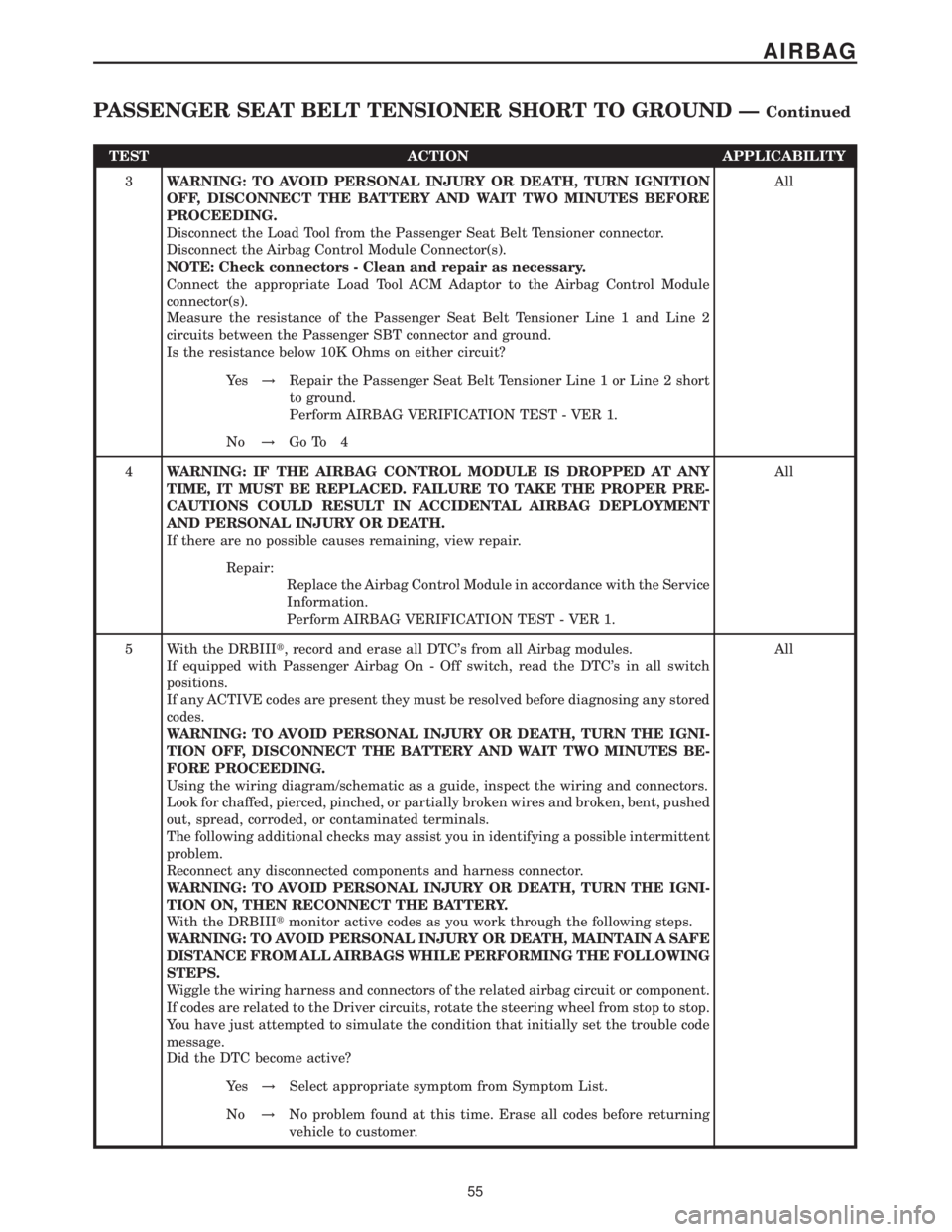
TEST ACTION APPLICABILITY
3WARNING: TO AVOID PERSONAL INJURY OR DEATH, TURN IGNITION
OFF, DISCONNECT THE BATTERY AND WAIT TWO MINUTES BEFORE
PROCEEDING.
Disconnect the Load Tool from the Passenger Seat Belt Tensioner connector.
Disconnect the Airbag Control Module Connector(s).
NOTE: Check connectors - Clean and repair as necessary.
Connect the appropriate Load Tool ACM Adaptor to the Airbag Control Module
connector(s).
Measure the resistance of the Passenger Seat Belt Tensioner Line 1 and Line 2
circuits between the Passenger SBT connector and ground.
Is the resistance below 10K Ohms on either circuit?All
Ye s!Repair the Passenger Seat Belt Tensioner Line 1 or Line 2 short
to ground.
Perform AIRBAG VERIFICATION TEST - VER 1.
No!Go To 4
4WARNING: IF THE AIRBAG CONTROL MODULE IS DROPPED AT ANY
TIME, IT MUST BE REPLACED. FAILURE TO TAKE THE PROPER PRE-
CAUTIONS COULD RESULT IN ACCIDENTAL AIRBAG DEPLOYMENT
AND PERSONAL INJURY OR DEATH.
If there are no possible causes remaining, view repair.All
Repair:
Replace the Airbag Control Module in accordance with the Service
Information.
Perform AIRBAG VERIFICATION TEST - VER 1.
5 With the DRBIIIt, record and erase all DTC's from all Airbag modules.
If equipped with Passenger Airbag On - Off switch, read the DTC's in all switch
positions.
If any ACTIVE codes are present they must be resolved before diagnosing any stored
codes.
WARNING: TO AVOID PERSONAL INJURY OR DEATH, TURN THE IGNI-
TION OFF, DISCONNECT THE BATTERY AND WAIT TWO MINUTES BE-
FORE PROCEEDING.
Using the wiring diagram/schematic as a guide, inspect the wiring and connectors.
Look for chaffed, pierced, pinched, or partially broken wires and broken, bent, pushed
out, spread, corroded, or contaminated terminals.
The following additional checks may assist you in identifying a possible intermittent
problem.
Reconnect any disconnected components and harness connector.
WARNING: TO AVOID PERSONAL INJURY OR DEATH, TURN THE IGNI-
TION ON, THEN RECONNECT THE BATTERY.
With the DRBIIItmonitor active codes as you work through the following steps.
WARNING: TO AVOID PERSONAL INJURY OR DEATH, MAINTAIN A SAFE
DISTANCE FROM ALL AIRBAGS WHILE PERFORMING THE FOLLOWING
STEPS.
Wiggle the wiring harness and connectors of the related airbag circuit or component.
If codes are related to the Driver circuits, rotate the steering wheel from stop to stop.
You have just attempted to simulate the condition that initially set the trouble code
message.
Did the DTC become active?All
Ye s!Select appropriate symptom from Symptom List.
No!No problem found at this time. Erase all codes before returning
vehicle to customer.
55
AIRBAG
PASSENGER SEAT BELT TENSIONER SHORT TO GROUND ÐContinued
Page 263 of 2305
8.4 CLOCKSPRING
8.5 SEAT BELT TENSIONER
8.6 HEATING & A/C
8.6.1 AUTOMATIC TEMPERATURE CONTROL (ATC) SYSTEM COMPONENTS
C
O
M
P
O
N
E
N
T
L
O
C
A
T
I
O
N
S
250
COMPONENT LOCATIONS
Page 270 of 2305
9.0 CONNECTOR PINOUTS
A/C AUXILIARY FANCAV CIRCUIT FUNCTION
1 14DG/BK A/C AUXILIARY FAN RELAY OUTPUT
2 14BR GROUND
AIR OUTLET TEMPERATURE SENSORCAV CIRCUIT FUNCTION
1 18BR/GY AIR OUTLET TEMPERATURE SENSOR SIGNAL
2 18BR/BL SENSOR GROUND
AIRBAG CONTROL MODULE - YELLOWCAV CIRCUIT FUNCTION
1 20BL DRIVER SEAT BELT TENSIONER LINE 2
2 20BR/YL DRIVER SEAT BELT TENSIONER LINE 1
3 20BL PASSENGER SEAT BELT TENSIONER LINE 2
4 20BR PASSENGER SEAT BELT TENSIONER LINE 1
5 20BK FUSED IGNITION SWITCH OUTPUT (RUN-START)
6 20BR GROUND
7 20YL AIRBAG WARNING INDICATOR DRIVER
8- -
9 20BK/RD K-ACM
10 20DG DRIVER AIRBAG SQUIB 1 LINE 2
11 20VT DRIVER AIRBAG SQUIB 1 LINE 1
12 - -
13 20BL/DG PASSENGER AIRBAG SQUIB 1 LINE 2
14 20BR/DG PASSENGER AIRBAG SQUIB 1 LINE 1
15 - -
16 - -
17 - -
18 - -
19 - -
20 20DG ENHANCED ACCIDENT REPORT DRIVER
21 -
22 -
23 -
24 -
25 -
C
O
N
N
E
C
T
O
R
P
I
N
O
U
T
S
257
CONNECTOR PINOUTS
Page 292 of 2305

INSTRUMENT CLUSTER C1CAV CIRCUIT FUNCTION
1 20BR FUEL LEVEL SENSOR SIGNAL RETURN
2 20BR/DG AMBIENT TEMPERATURE SENSOR SIGNAL RETURN
4 20WT/GY K-IC/ATC/HBM/CHM
5 20BR/BK PARK BRAKE INDICATOR SIGNAL
7 20BK/DG RIGHT TURN SIGNAL
10 20BL/BK FUEL LEVEL SENSOR SIGNAL (+)
11 20BL/DG AMBIENT TEMPERATURE SENSOR SIGNAL (+)
14 20DG/WT/BL ENGINE COOLANT LEVEL SWITCH SIGNAL
15 20BR/WT FRONT COURTESY LAMPS CONTROL
16 20YL/RD SEAT BELT SWITCH SIGNAL
17 20DG CAN C BUS (-)
18 20DG/WT CAN C BUS (+)
INSTRUMENT CLUSTER C2 - WHITECAV CIRCUIT FUNCTION
1- -
2- -
3 20RD/YL FUSED B(+)
4 20BR/WT BRAKE WEAR SENSOR SIGNAL
5- -
6 18BR GROUND
7 20GY/DG/RD LAMP DRIVER
8 20BL/WT FUSED HIGH BEAM SWITCH OUTPUT
9 20BL/RD/WT VEHICLE SPEED SENSOR OUTPUT
10 20BK FUSED IGNITION SWITCH OUTPUT (RUN-START)
11 20BL/BK KEY-IN IGNITION SWITCH SIGNAL
12 - -
13 20BK/WT LEFT TURN SIGNAL
14 20BR/YL BRAKE FLUID LEVEL INDICATOR SIGNAL
15 20BL GENERATOR FIELD DRIVER
16 20YL AIRBAG WARNING INDICATOR DRIVER
17 - -
18 20BL/VT D(+) RELAY NO. 1 CONTROL
18 20BL/VT D(+) RELAY NO. 1 CONTROL
INTRUSION SENSOR NO. 1 - BLACKCAV CIRCUIT FUNCTION
1 20BR GROUND
2 20DG/BK INTRUSION SENSOR 1 SIGNAL
3 20DG/YL INTRUSION SENSOR INTERFACE
4 20RD/DG FUSED B(+)
INTRUSION SENSOR NO. 2 - BLACKCAV CIRCUIT FUNCTION
1 20BR GROUND
2 20GY/BK INTRUSION SENSOR 2 SIGNAL
3 20DG/YL INTRUSION SENSOR INTERFACE
4 20RD/DG FUSED B(+)
C
O
N
N
E
C
T
O
R
P
I
N
O
U
T
S
279
CONNECTOR PINOUTS
Page 297 of 2305
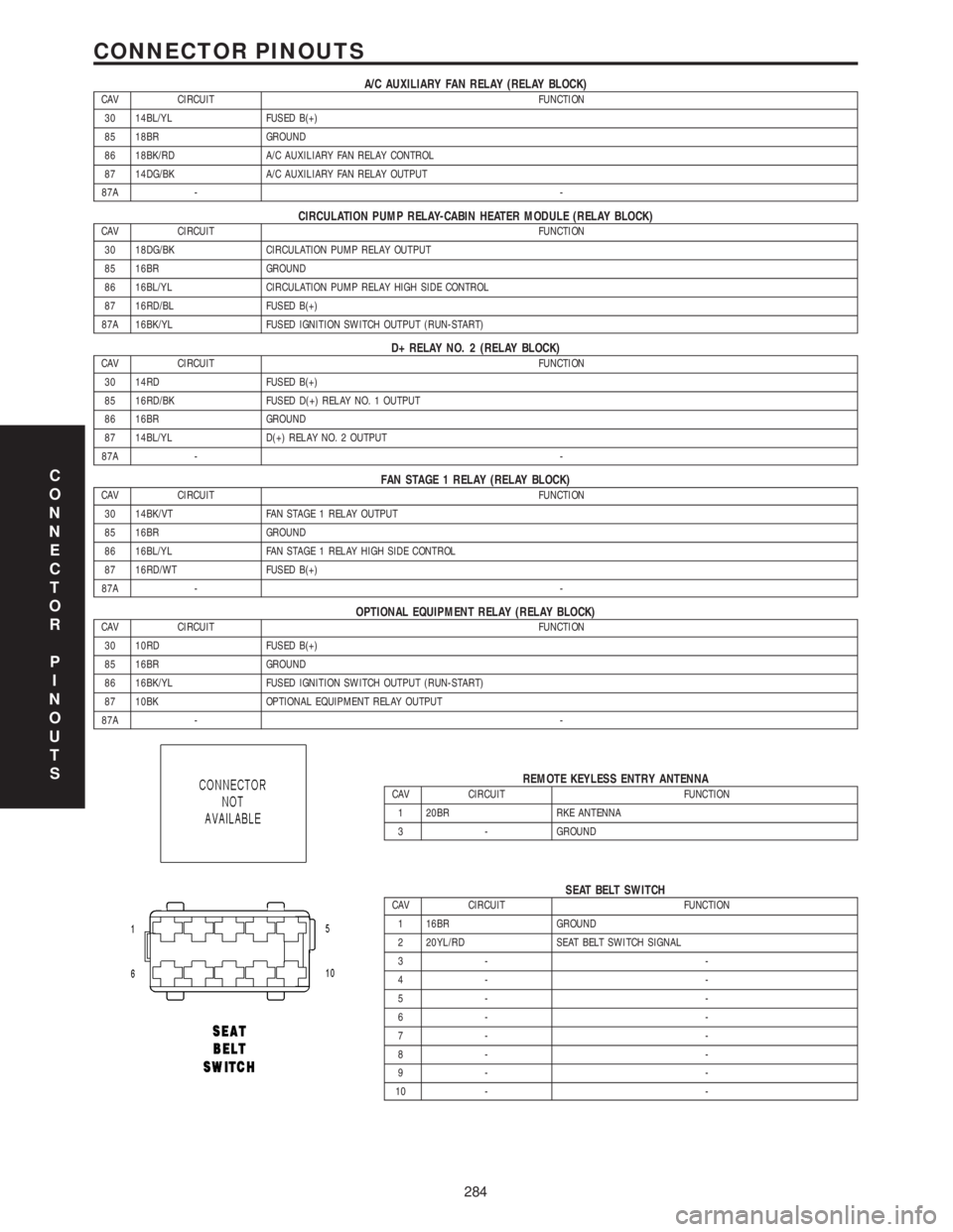
A/C AUXILIARY FAN RELAY (RELAY BLOCK)CAV CIRCUIT FUNCTION
30 14BL/YL FUSED B(+)
85 18BR GROUND
86 18BK/RD A/C AUXILIARY FAN RELAY CONTROL
87 14DG/BK A/C AUXILIARY FAN RELAY OUTPUT
87A --
CIRCULATION PUMP RELAY-CABIN HEATER MODULE (RELAY BLOCK)CAV CIRCUIT FUNCTION
30 18DG/BK CIRCULATION PUMP RELAY OUTPUT
85 16BR GROUND
86 16BL/YL CIRCULATION PUMP RELAY HIGH SIDE CONTROL
87 16RD/BL FUSED B(+)
87A 16BK/YL FUSED IGNITION SWITCH OUTPUT (RUN-START)
D+ RELAY NO. 2 (RELAY BLOCK)CAV CIRCUIT FUNCTION
30 14RD FUSED B(+)
85 16RD/BK FUSED D(+) RELAY NO. 1 OUTPUT
86 16BR GROUND
87 14BL/YL D(+) RELAY NO. 2 OUTPUT
87A --
FAN STAGE 1 RELAY (RELAY BLOCK)CAV CIRCUIT FUNCTION
30 14BK/VT FAN STAGE 1 RELAY OUTPUT
85 16BR GROUND
86 16BL/YL FAN STAGE 1 RELAY HIGH SIDE CONTROL
87 16RD/WT FUSED B(+)
87A --
OPTIONAL EQUIPMENT RELAY (RELAY BLOCK)CAV CIRCUIT FUNCTION
30 10RD FUSED B(+)
85 16BR GROUND
86 16BK/YL FUSED IGNITION SWITCH OUTPUT (RUN-START)
87 10BK OPTIONAL EQUIPMENT RELAY OUTPUT
87A --
REMOTE KEYLESS ENTRY ANTENNACAV CIRCUIT FUNCTION
1 20BR RKE ANTENNA
3 - GROUND
SEAT BELT SWITCHCAV CIRCUIT FUNCTION
1 16BR GROUND
2 20YL/RD SEAT BELT SWITCH SIGNAL
3- -
4- -
5- -
6- -
7- -
8- -
9- -
10 - -
C
O
N
N
E
C
T
O
R
P
I
N
O
U
T
S
284
CONNECTOR PINOUTS