2006 MERCEDES-BENZ SPRINTER fuel type
[x] Cancel search: fuel typePage 721 of 2305
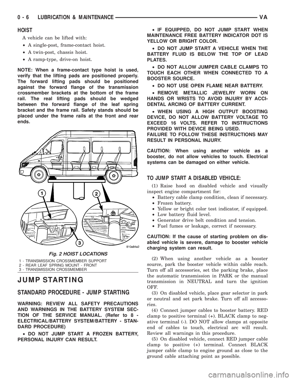
HOIST
A vehicle can be lifted with:
²A single-post, frame-contact hoist.
²A twin-post, chassis hoist.
²A ramp-type, drive-on hoist.
NOTE: When a frame-contact type hoist is used,
verify that the lifting pads are positioned properly.
The forward lifting pads should be positioned
against the forward flange of the transmission
crossmember brackets at the bottom of the frame
rail. The real lifting pads should be wedged
between the forward flange of the leaf spring
bracket and the frame rail. Safety stands should be
placed under the frame rails at the front and rear
ends.
JUMP STARTING
STANDARD PROCEDURE - JUMP STARTING
WARNING: REVIEW ALL SAFETY PRECAUTIONS
AND WARNINGS IN THE BATTERY SYSTEM SEC-
TION OF THE SERVICE MANUAL. (Refer to 8 -
ELECTRICAL/BATTERY SYSTEM/BATTERY - STAN-
DARD PROCEDURE)
²DO NOT JUMP START A FROZEN BATTERY,
PERSONAL INJURY CAN RESULT.²IF EQUIPPED, DO NOT JUMP START WHEN
MAINTENANCE FREE BATTERY INDICATOR DOT IS
YELLOW OR BRIGHT COLOR.
²DO NOT JUMP START A VEHICLE WHEN THE
BATTERY FLUID IS BELOW THE TOP OF LEAD
PLATES.
²DO NOT ALLOW JUMPER CABLE CLAMPS TO
TOUCH EACH OTHER WHEN CONNECTED TO A
BOOSTER SOURCE.
²DO NOT USE OPEN FLAME NEAR BATTERY.
²REMOVE METALLIC JEWELRY WORN ON
HANDS OR WRISTS TO AVOID INJURY BY ACCI-
DENTAL ARCING OF BATTERY CURRENT.
²WHEN USING A HIGH OUTPUT BOOSTING
DEVICE, DO NOT ALLOW BATTERY VOLTAGE TO
EXCEED 16 VOLTS. REFER TO INSTRUCTIONS
PROVIDED WITH DEVICE BEING USED.
FAILURE TO FOLLOW THESE INSTRUCTIONS MAY
RESULT IN PERSONAL INJURY.
CAUTION: When using another vehicle as a
booster, do not allow vehicles to touch. Electrical
systems can be damaged on either vehicle.
TO JUMP START A DISABLED VEHICLE:
(1) Raise hood on disabled vehicle and visually
inspect engine compartment for:
²Battery cable clamp condition, clean if necessary.
²Frozen battery.
²Yellow or bright color test indicator, if equipped.
²Low battery fluid level.
²Generator drive belt condition and tension.
²Fuel fumes or leakage, correct if necessary.
CAUTION: If the cause of starting problem on dis-
abled vehicle is severe, damage to booster vehicle
charging system can result.
(2) When using another vehicle as a booster
source, park the booster vehicle within cable reach.
Turn off all accessories, set the parking brake, place
the automatic transmission in PARK or the manual
transmission in NEUTRAL and turn the ignition
OFF.
(3) On disabled vehicle, place gear selector in park
or neutral and set park brake. Turn off all accesso-
ries.
(4) Connect jumper cables to booster battery. RED
clamp to positive terminal (+). BLACK clamp to neg-
ative terminal (-). DO NOT allow clamps at opposite
end of cables to touch, electrical arc will result.
Review all warnings in this procedure.
(5) On disabled vehicle, connect RED jumper cable
clamp to positive (+) terminal. Connect BLACK
jumper cable clamp to engine ground as close to the
ground cable attaching point as possible.
Fig. 2 HOIST LOCATIONS
1 - TRANSMISSION CROSSMEMBER SUPPORT
2 - REAR LEAF SPRING MOUNT - FRONT
3 - TRANSMISSION CROSSMEMBER
0 - 6 LUBRICATION & MAINTENANCEVA
Page 723 of 2305
effect panels. If necessary, remove the wheels from
the lifted end of the vehicle and lower the vehicle
closer to the ground, to increase the ground clearance
at the opposite end of the vehicle. Install lug nuts on
wheel attaching studs to retain brake drums.
RAMP ANGLE
If a vehicle with flat-bed towing equipment is used,
the approach ramp angle should not exceed 15
degrees.
TOWING WHEN KEYS ARE NOT AVAILABLE
When the vehicle is locked and keys are not avail-
able, use a flat bed hauler. A Wheel-lift or Sling-type
device can be used provided all the wheels are lifted
off the ground using tow dollies.
MAINTENANCE SCHEDULES
DESCRIPTION
The use of special lubricant additives is not recom-
mended. The use of such additives may affect the
warranty rights. With regard to legal stipulations
concerning emissions control, please note that
engines have to be serviced and adjusted in accor-
dance with special instructions and using special
measuring equipment. Modifications to or interfer-
ence with the emissions control systems are not per-
missible.
MAINTENANCE - WITHOUT ASSYST MAINTE-
NANCE COMPUTER
Maintenance Intervals
²Oil service ±Normal Operationevery 10,000
miles or 16,000 km or 12 months.
²Maintenance service every 30,000 miles or
48,000 km.
Additional work must be carried out at yearly
intervals.
MAINTENANCE - WITH ASSYST MAINTENANCE
COMPUTER
ASSYST provides information on the best possible
timing for maintenance work.
When the next maintenance service is due, this
will be indicated in the multi-function display with
the wrench icon symbol displayed in km/miles or
days.
²One wrench icon showing indicates Oil Service
is necessary.
²Two wrench icons showing indicates Mainte-
nance Service is necessary ± displayed in km/miles or
days.
If the display shows the number of days, a clock
symbol will also appear in the multi-function display.You should have the maintenance performed
within the stated period/distance.
The service indicator will be reset after an oil ser-
vice and/or maintenance service has been performed.
REGULAR CHECK - UPS
To maintain the safe operation of the vehicle, it is
recommended that the following tasks be performed
on a regular basis (i.e. weekly or whenever the vehi-
cle is refueled). Check:
²Engine oil level
²Brake system - fluid level
²Battery - acid level
²Windshield washer system and headlamp clean-
ing system - fluid level
²Mechanical assemblies (e.g. engine, transmis-
sion, etc.) - check for leaks
²Condition of tires and tires pressures
²All exterior lights
SPECIAL MAINTENANCE REQUIREMENTS
If bodies built by manufacturers other than
DaimlerChrysler Corporation are fitted to the vehi-
cle, the maintenance requirements and lubrication
intervals specified by the body manufacturer must be
adhered to, in addition to all standard maintenance
requirements.
Coolant
Corrosion inhibitor/antifreeze concentration in the
coolant should be checked before the onset of winter
(once year in countries with high prevailing temper-
atures).
Replace the coolant every five years or 100,000
miles.
Dust Filter for Heating / Ventilation Replacement
The dust filter and the tailgate interior filter are to
be renewed during routine maintenance service. If
operating conditions are dusty, these filters should be
renewed more frequently.
ENGINE OIL CHANGE AND FILTER REPLACEMENT
At a minimum, change the engine oil and oil filter
once a year ± even if the vehicle mileage per year is
extremely low. For standard oil service schedules
refer to the chapter oil service and maintenance ser-
vice.
Once a Year
Select the viscosity of the engine oil (SAE classes)
according to the outside air temperature.
Only use engine oil approved by DaimlerChrysler
Corporation if following the ASSYST system guide-
lines.
0 - 8 LUBRICATION & MAINTENANCEVA
Page 922 of 2305

Located between the rear cover and the cluster
hood is the cluster housing. The molded plastic clus-
ter housing serves as the carrier for the cluster elec-
tronic circuit board and circuitry, the cluster
connector receptacles, the gauges, a Light Emitting
Diode (LED) for each cluster indicator and general
illumination lamp, the multi-function indicator LCD
unit, electronic tone generators, the cluster overlay,
the gauge pointers, the multi-function indicator
switches and the four switch push buttons.
The cluster overlay is a laminated plastic unit. The
dark, visible, outer surface of the overlay is marked
with all of the gauge dial faces and graduations, but
this layer is also translucent. The darkness of this
outer layer prevents the cluster from appearing clut-
tered or busy by concealing the cluster indicators
that are not illuminated, while the translucence of
this layer allows those indicators and icons that are
illuminated to be readily visible. The underlying
layer of the overlay is opaque and allows light from
the LED for each of the various indicators and illu-
mination lamps behind it to be visible through the
outer layer of the overlay only through predeter-
mined cutouts. A rectangular opening in the overlay
at the base of the speedometer provides a window
through which the illuminated multi-function indica-
tor LCD unit can be viewed.
Several versions of the EMIC module are offered
on this model. These versions accommodate all of the
variations of optional equipment and regulatory
requirements for the various markets in which the
vehicle will be offered. The microprocessor-based
EMIC utilizes integrated circuitry, Electrically Eras-
able Programmable Read Only Memory (EEPROM)
type memory storage, information carried on the
Controller Area Network (CAN) data bus, along with
several hard wired analog and multiplexed inputs to
monitor systems, sensors and switches throughout
the vehicle.
In response to those inputs, the hardware and soft-
ware of the EMIC allow it to control and integrate
many electronic functions and features of the vehicle
through both hard wired outputs and the transmis-
sion of electronic message outputs to other electronic
modules in the vehicle over the CAN data bus. (Refer
to 8 - ELECTRICAL/ELECTRONIC CONTROL
MODULES/COMMUNICATION - DESCRIPTION -
CAN BUS).
Besides typical instrument cluster gauge and indi-
cator support, the electronic functions and features
that the EMIC supports or controls include the fol-
lowing:
²Active Service System- In vehicles equipped
with the Active Service SYSTem (ASSYST) engine oil
maintenance indicator option, the EMIC electronic
circuit board includes a second dedicated micropro-
cessor. This second microprocessor evaluates various
data including time, mileage, and driving conditionsto calculate the required engine oil service intervals,
and provides both visual and audible alerts to the
vehicle operator when certain engine oil maintenance
services are required.
²Audible Warnings- The EMIC electronic cir-
cuit board is equipped with an audible tone generator
and programming that allows it to provide various
audible alerts to the vehicle operator, including buzz-
ing and chime tones. An audible contactless elec-
tronic relay is also soldered onto the circuit board to
produce audible clicks that is synchronized with turn
signal indicator flashing to emulate the sounds of a
conventional turn signal or hazard warning flasher.
These audible clicks can occur at one of two rates to
emulate both normal and bulb-out turn or hazard
flasher operation. (Refer to 8 - ELECTRICAL/
CHIME/BUZZER - DESCRIPTION).
²Panel Lamps Dimming Control- The EMIC
provides a hard wired 12-volt Pulse-Width Modulated
(PWM) output that synchronizes the dimming level
of all panel lamps dimmer controlled lamps with that
of the cluster general illumination lamps and multi-
function indicator.
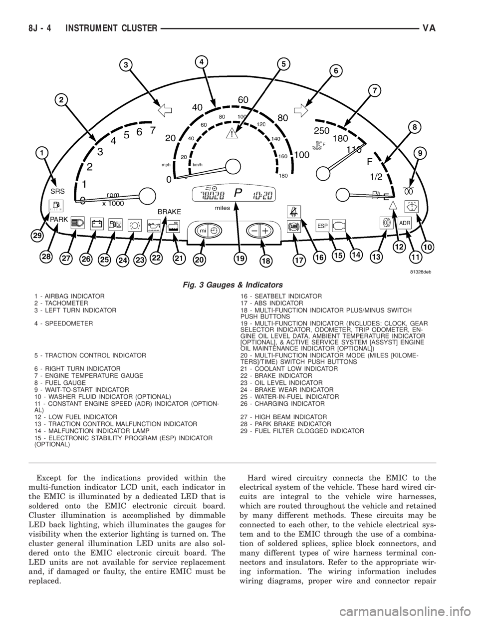
The EMIC houses four analog gauges and has pro-
visions for up to nineteen indicators (Fig. 3). The
EMIC includes the following analog gauges:
²Coolant Temperature Gauge
²Fuel Gauge
²Speedometer
²Tachometer
The EMIC includes provisions for the following
indicators (Fig. 3):
²Airbag (SRS) Indicator
²Antilock Brake System (ABS) Indicator
²Brake Indicator
²Brake Wear Indicator
²Charging Indicator
²Clogged Fuel Filter Indicator
²Constant Engine Speed (ADR) Indicator
²Coolant Low Indicator
²Electronic Stability Program (ESP) Indica-
tor
²High Beam Indicator
²Low Fuel Indicator
²Malfunction Indicator Lamp (MIL)
²Multi-Function Indicator (LCD)
²Park Brake Indicator
²Seatbelt Indicator
²Traction Control (ASR) Indicator
²Traction Control (ASR) Malfunction Indica-
tor
²Turn Signal (Right and Left) Indicators
²Washer Fluid Indicator
²Wait-To-Start Indicator
²Water-In-Fuel Indicator
VAINSTRUMENT CLUSTER 8J - 3
Page 923 of 2305
Except for the indications provided within the
multi-function indicator LCD unit, each indicator in
the EMIC is illuminated by a dedicated LED that is
soldered onto the EMIC electronic circuit board.
Cluster illumination is accomplished by dimmable
LED back lighting, which illuminates the gauges for
visibility when the exterior lighting is turned on. The
cluster general illumination LED units are also sol-
dered onto the EMIC electronic circuit board. The
LED units are not available for service replacement
and, if damaged or faulty, the entire EMIC must be
replaced.Hard wired circuitry connects the EMIC to the
electrical system of the vehicle. These hard wired cir-
cuits are integral to the vehicle wire harnesses,
which are routed throughout the vehicle and retained
by many different methods. These circuits may be
connected to each other, to the vehicle electrical sys-
tem and to the EMIC through the use of a combina-
tion of soldered splices, splice block connectors, and
many different types of wire harness terminal con-
nectors and insulators. Refer to the appropriate wir-
ing information. The wiring information includes
wiring diagrams, proper wire and connector repair
Fig. 3 Gauges & Indicators
1 - AIRBAG INDICATOR 16 - SEATBELT INDICATOR
2 - TACHOMETER 17 - ABS INDICATOR
3 - LEFT TURN INDICATOR 18 - MULTI-FUNCTION INDICATOR PLUS/MINUS SWITCH
PUSH BUTTONS
4 - SPEEDOMETER 19 - MULTI-FUNCTION INDICATOR (INCLUDES: CLOCK, GEAR
SELECTOR INDICATOR, ODOMETER, TRIP ODOMETER, EN-
GINE OIL LEVEL DATA, AMBIENT TEMPERATURE INDICATOR
[OPTIONAL], & ACTIVE SERVICE SYSTEM [ASSYST] ENGINE
OIL MAINTENANCE INDICATOR [OPTIONAL])
5 - TRACTION CONTROL INDICATOR 20 - MULTI-FUNCTION INDICATOR MODE (MILES [KILOME-
TERS]/TIME) SWITCH PUSH BUTTONS
6 - RIGHT TURN INDICATOR 21 - COOLANT LOW INDICATOR
7 - ENGINE TEMPERATURE GAUGE 22 - BRAKE INDICATOR
8 - FUEL GAUGE 23 - OIL LEVEL INDICATOR
9 - WAIT-TO-START INDICATOR 24 - BRAKE WEAR INDICATOR
10 - WASHER FLUID INDICATOR (OPTIONAL) 25 - WATER-IN-FUEL INDICATOR
11 - CONSTANT ENGINE SPEED (ADR) INDICATOR (OPTION-
AL)26 - CHARGING INDICATOR
12 - LOW FUEL INDICATOR 27 - HIGH BEAM INDICATOR
13 - TRACTION CONTROL MALFUNCTION INDICATOR 28 - PARK BRAKE INDICATOR
14 - MALFUNCTION INDICATOR LAMP 29 - FUEL FILTER CLOGGED INDICATOR
15 - ELECTRONIC STABILITY PROGRAM (ESP) INDICATOR
(OPTIONAL)
8J - 4 INSTRUMENT CLUSTERVA
Page 1008 of 2305
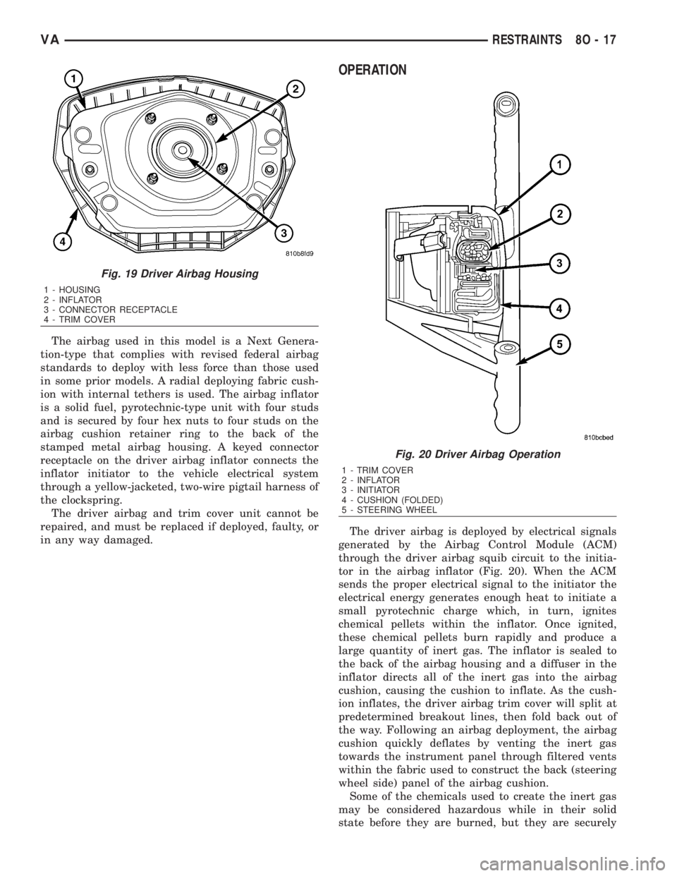
The airbag used in this model is a Next Genera-
tion-type that complies with revised federal airbag
standards to deploy with less force than those used
in some prior models. A radial deploying fabric cush-
ion with internal tethers is used. The airbag inflator
is a solid fuel, pyrotechnic-type unit with four studs
and is secured by four hex nuts to four studs on the
airbag cushion retainer ring to the back of the
stamped metal airbag housing. A keyed connector
receptacle on the driver airbag inflator connects the
inflator initiator to the vehicle electrical system
through a yellow-jacketed, two-wire pigtail harness of
the clockspring.
The driver airbag and trim cover unit cannot be
repaired, and must be replaced if deployed, faulty, or
in any way damaged.
OPERATION
The driver airbag is deployed by electrical signals
generated by the Airbag Control Module (ACM)
through the driver airbag squib circuit to the initia-
tor in the airbag inflator (Fig. 20). When the ACM
sends the proper electrical signal to the initiator the
electrical energy generates enough heat to initiate a
small pyrotechnic charge which, in turn, ignites
chemical pellets within the inflator. Once ignited,
these chemical pellets burn rapidly and produce a
large quantity of inert gas. The inflator is sealed to
the back of the airbag housing and a diffuser in the
inflator directs all of the inert gas into the airbag
cushion, causing the cushion to inflate. As the cush-
ion inflates, the driver airbag trim cover will split at
predetermined breakout lines, then fold back out of
the way. Following an airbag deployment, the airbag
cushion quickly deflates by venting the inert gas
towards the instrument panel through filtered vents
within the fabric used to construct the back (steering
wheel side) panel of the airbag cushion.
Some of the chemicals used to create the inert gas
may be considered hazardous while in their solid
state before they are burned, but they are securely
Fig. 19 Driver Airbag Housing
1 - HOUSING
2 - INFLATOR
3 - CONNECTOR RECEPTACLE
4 - TRIM COVER
Fig. 20 Driver Airbag Operation
1 - TRIM COVER
2 - INFLATOR
3 - INITIATOR
4 - CUSHION (FOLDED)
5 - STEERING WHEEL
VARESTRAINTS 8O - 17
Page 1015 of 2305
(3) If the vehicle is so equipped, snap the plastic
cover over the screw that secures the front seat belt
buckle lower anchor to the inboard side of the seat
frame.
(4) On the driver side only, reconnect the seat belt
switch pigtail wire to the vehicle wire harness and
push the joined connectors through the clearance
hole in the seat riser cover.
(5) On the driver side only, route and secure the
seat belt switch pigtail wire to the seat frame with
wire ties.
PASSENGER AIRBAG
DESCRIPTION
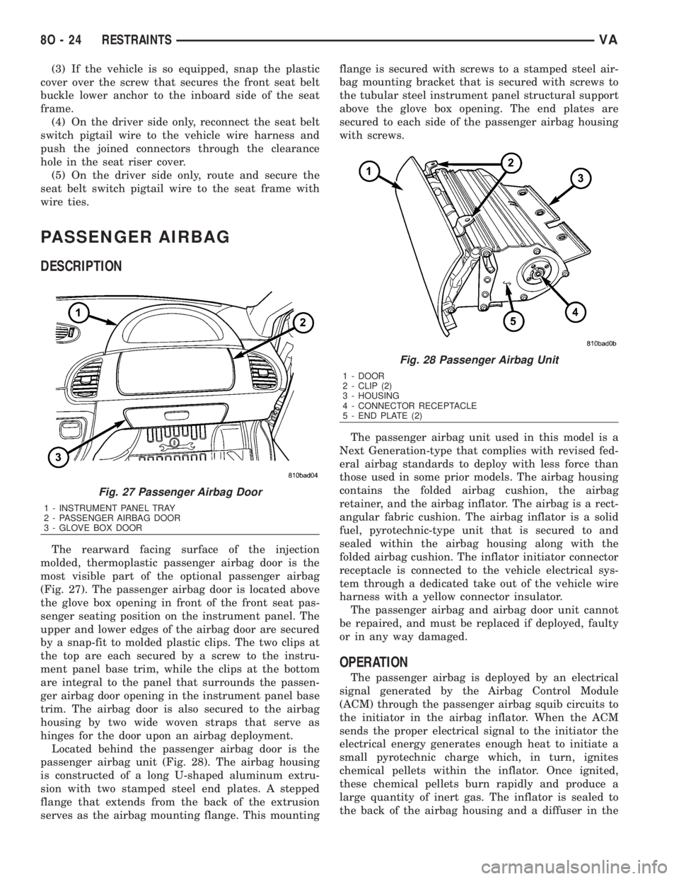
The rearward facing surface of the injection
molded, thermoplastic passenger airbag door is the
most visible part of the optional passenger airbag
(Fig. 27). The passenger airbag door is located above
the glove box opening in front of the front seat pas-
senger seating position on the instrument panel. The
upper and lower edges of the airbag door are secured
by a snap-fit to molded plastic clips. The two clips at
the top are each secured by a screw to the instru-
ment panel base trim, while the clips at the bottom
are integral to the panel that surrounds the passen-
ger airbag door opening in the instrument panel base
trim. The airbag door is also secured to the airbag
housing by two wide woven straps that serve as
hinges for the door upon an airbag deployment.
Located behind the passenger airbag door is the
passenger airbag unit (Fig. 28). The airbag housing
is constructed of a long U-shaped aluminum extru-
sion with two stamped steel end plates. A stepped
flange that extends from the back of the extrusion
serves as the airbag mounting flange. This mountingflange is secured with screws to a stamped steel air-
bag mounting bracket that is secured with screws to
the tubular steel instrument panel structural support
above the glove box opening. The end plates are
secured to each side of the passenger airbag housing
with screws.
The passenger airbag unit used in this model is a
Next Generation-type that complies with revised fed-
eral airbag standards to deploy with less force than
those used in some prior models. The airbag housing
contains the folded airbag cushion, the airbag
retainer, and the airbag inflator. The airbag is a rect-
angular fabric cushion. The airbag inflator is a solid
fuel, pyrotechnic-type unit that is secured to and
sealed within the airbag housing along with the
folded airbag cushion. The inflator initiator connector
receptacle is connected to the vehicle electrical sys-
tem through a dedicated take out of the vehicle wire
harness with a yellow connector insulator.
The passenger airbag and airbag door unit cannot
be repaired, and must be replaced if deployed, faulty
or in any way damaged.
OPERATION
The passenger airbag is deployed by an electrical
signal generated by the Airbag Control Module
(ACM) through the passenger airbag squib circuits to
the initiator in the airbag inflator. When the ACM
sends the proper electrical signal to the initiator the
electrical energy generates enough heat to initiate a
small pyrotechnic charge which, in turn, ignites
chemical pellets within the inflator. Once ignited,
these chemical pellets burn rapidly and produce a
large quantity of inert gas. The inflator is sealed to
the back of the airbag housing and a diffuser in the
Fig. 27 Passenger Airbag Door
1 - INSTRUMENT PANEL TRAY
2 - PASSENGER AIRBAG DOOR
3 - GLOVE BOX DOOR
Fig. 28 Passenger Airbag Unit
1 - DOOR
2 - CLIP (2)
3 - HOUSING
4 - CONNECTOR RECEPTACLE
5 - END PLATE (2)
8O - 24 RESTRAINTSVA
Page 1585 of 2305
(11) Install the torque converter access plate. Refer
to (Refer to 21 - TRANSMISSION/TRANSAXLE/AU-
TOMATIC - NAG1 - INSTALLATION) for correct
sequence and torque specification.
(12) Install the transmission cooler lines to trans-
mission. (Refer to 21 - TRANSMISSION/TRANS-
AXLE/AUTOMATIC - NAG1 - INSTALLATION) for
correct sequence and torque specification.
(13) Connect the engine valley drain hose to the
transmission (Fig. 5).
(14) Install transmission electrical connector and
shifter hardware. Refer to (Refer to 21 - TRANSMIS-
SION/TRANSAXLE/AUTOMATIC - NAG1 - INSTAL-
LATION) for correct sequence and torque
specification.
(15) Install the steering gear and tighten in two
stages. 25 N´m (18.5 lbs. ft.), then 45 N´m (33 lbs. ft.)
plus 90É.
(16) Install the starter.
(17) Connect the ground strap (left side).
(18) Align and install the exhaust and bracket
(Refer to 11 - EXHAUST SYSTEM/EXHAUST PIPE -
INSTALLATION).
(19) Lower the vehicle.
(20) Install the lower heater housing and filter.
(21) Install the air inlet hose, CCV breather and
CCV heater at the turbocharger (Fig. 4).
(22) Connect the coolant supply and return hoses.
(23) Connect the brake booster vacuum hose at the
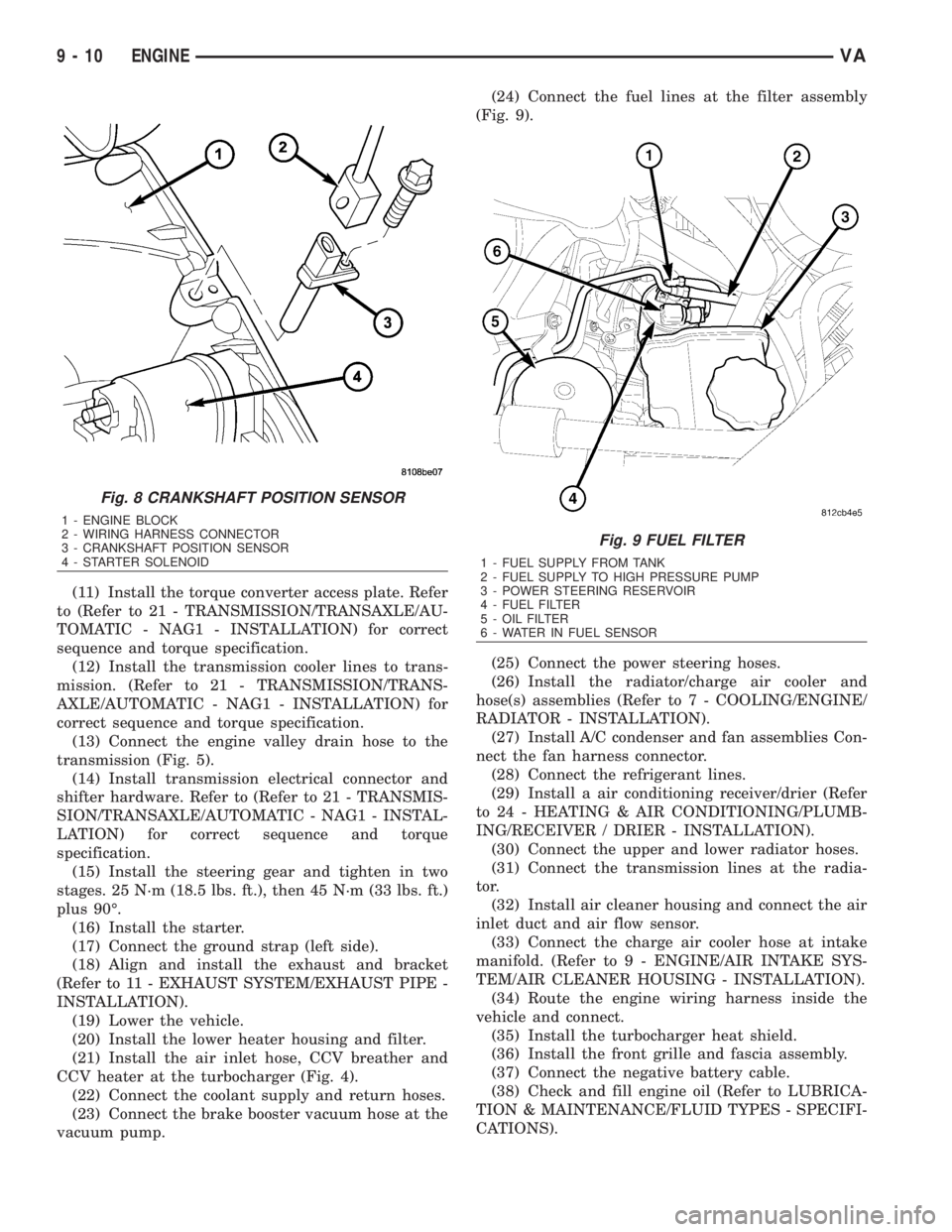
vacuum pump.(24) Connect the fuel lines at the filter assembly
(Fig. 9).
(25) Connect the power steering hoses.
(26) Install the radiator/charge air cooler and
hose(s) assemblies (Refer to 7 - COOLING/ENGINE/
RADIATOR - INSTALLATION).
(27) Install A/C condenser and fan assemblies Con-
nect the fan harness connector.
(28) Connect the refrigerant lines.
(29) Install a air conditioning receiver/drier (Refer
to 24 - HEATING & AIR CONDITIONING/PLUMB-
ING/RECEIVER / DRIER - INSTALLATION).
(30) Connect the upper and lower radiator hoses.
(31) Connect the transmission lines at the radia-
tor.
(32) Install air cleaner housing and connect the air
inlet duct and air flow sensor.
(33) Connect the charge air cooler hose at intake
manifold. (Refer to 9 - ENGINE/AIR INTAKE SYS-
TEM/AIR CLEANER HOUSING - INSTALLATION).
(34) Route the engine wiring harness inside the
vehicle and connect.
(35) Install the turbocharger heat shield.
(36) Install the front grille and fascia assembly.
(37) Connect the negative battery cable.
(38) Check and fill engine oil (Refer to LUBRICA-
TION & MAINTENANCE/FLUID TYPES - SPECIFI-
CATIONS).
Fig. 8 CRANKSHAFT POSITION SENSOR
1 - ENGINE BLOCK
2 - WIRING HARNESS CONNECTOR
3 - CRANKSHAFT POSITION SENSOR
4 - STARTER SOLENOID
Fig. 9 FUEL FILTER
1 - FUEL SUPPLY FROM TANK
2 - FUEL SUPPLY TO HIGH PRESSURE PUMP
3 - POWER STEERING RESERVOIR
4 - FUEL FILTER
5 - OIL FILTER
6 - WATER IN FUEL SENSOR
9 - 10 ENGINEVA
Page 1660 of 2305
CATALYTIC CONVERTER
REMOVAL
(1) Raise and support the vehicle.
(2) Saturate the clamp nuts with heat valve lubri-
cant. Allow 5 minutes for penetration. Remove the
rear clamp. (Fig. 1)
(3) Saturate the clamp nuts with heat valve lubri-
cant. Allow 5 minutes for penetration. Remove the
front clamp.
(4) Remove the cataylic converter and muffler
assembly from the isolators.
(5) Seperat the cataylic converter and muffler
assembly from the tailpipe and the exhaust pipe.
(6) Remove the cataylic converter and muffler
assembly and isolators from the vehicle.
(7) Remove the bolt, nut and front isolator from
the cataylic converter and muffler assembly.
(8) Remove the rear isolator from the cataylic con-
verter and muffler assembly.
(9)
INSTALLATION
(1) Install bolt, front isolator and nut (Fig. 1).
(2) Install rear insulator onto the cataylic con-
verter and muffler assembly
(3) Position the cataylic conveter and muffler
assembly into the exhaust pipe and tailpipe until
alignment tab is inserted into the alignment slot.
(4) Install the front and rear insulators.
(5) Install the real clamp.
(6) Install the front clamp.
(7) Lower vehicle.
(8) Start the vehicle and inspect for exhaust leaks.
Repair exhaust leaks as necessary.
(9) Check the exhaust system for contact with the
body panels. Make necessary adjustments, if neces-
sary.
EXHAUST PIPE
REMOVAL
(1) Raise and support the vehicle.
(2) Saturate the clamp nuts with heat valve lubri-
cant. Allow 5 minutes for penetration. Remove the
front and rear clamp (Fig. 1).
(3) Remove the mounting bracket nuts.
(4) Remove the exhaust pipe.
INSTALLATION
(1) Position the exhaust pipe into the exhaust pipe
into the cataylic converter and muffler assembly
until alignment tab is inserted into the alignment
slot.
(2) Install mounting bracket and nuts (Fig. 1).
(3) Install clamp.(4) Lower the vehicle.
(5) Start the vehicle and inspect for exhaust leaks.
Repair exhaust leaks as necessary.
(6) Check the exhaust system for contact with the
body panels. Make necessary adjustments, if neces-
sary.
TAILPIPE
REMOVAL
(1) Raise and support the vehicle.
(2) Saturate the clamp nuts with heat valve lubri-
cant. Allow 5 minutes for penetration (Fig. 1).
(3) Remove the clamp.
(4) Remove the tailpipe and insulator form the
vehicle
(5) Remove the insulator from the tailpipe.
INSTALLATION
(1) Position the tail pipe into the cataylic converter
and muffler assembly until alignment tab is inserted
into the alignment slot.
(2) Install the insulator.
(3) Install the clamp.
(4) Lower the vehicle.
(5) Start the vehicle and inspect for exhaust leaks.
Repair exhaust leaks as necessary.
(6) Check the exhaust system for contact with the
body panels. Make necessary adjustments, if neces-
sary.
TURBOCHARGER SYSTEM
DESCRIPTION
CAUTION: The turbocharger is a performance part
and must not be tampered with. The boost pressure
bracket is an integral part of the turbocharger. Tam-
pering with the boost pressure components can
reduce durability by increasing cylinder pressure
and thermal loading due to incorrect inlet and
exhaust manifold pressure. Poor fuel economy and
failure to meet regulatory emissions laws may
result. Increasing the turbocharger boost WILL NOT
increase engine power.
The turbocharger used on this vehicle is of the
variable turbine type. These turbochargers use the
entire exhaust energy to boost efficiency of the turbo-
charger and the engine.
The advantages of a turbocharger with variable
turbine geometry are:
²Higher charge pressure already in the lower and
in upper engine speed ranges.
²Higher torque as a result of improved cylinder
charge.
VAEXHAUST SYSTEM 11 - 3