Page 397 of 481
396 Practical hintsUnlocking/locking in an emergency1Locking�
Insert the mechanical key into the
driver’s door lock until it stops.
�
Turn the mechanical key clockwise to
position1.
The driver’s door is locked.Manually unlocking the gear selector
lever (automatic transmission*)
In case of power failure, the gear selector
lever can be manually unlocked, e.g. to tow
the vehicle.
1Gear selector lever cover
2Release
�
Insert flat, blunt object (e.g. screwdriv-
er) into the left edge of cover1 at the
position indicated by the arrows.
�
Loosen cover1 using this object.
�
Using your hands, pull cover1 out
and remove.
�
Push down and hold release2 in di-
rection of arrow.
�
Simultaneously move gear selector le-
ver out of positionP.
The gear selector lever is unlocked
now.iThe gear selector lever is locked again
as soon as you place it in positionP
again.
��
Page 398 of 481

397 Practical hints
Opening/closing in an emergency
�Opening/closing in an emergency
Raising retractable hardtop manuallyWarning!
G
If the retractable hardtop does not com-
pletely open or close, the roof hydraulics will
lose pressure and the retractable hardtop is
lowered�
after approximately 7 minutes when the
ignition is switched on
�
after approximately 15 seconds when
the ignition is switched off
Shortly before the hardtop is lowered, a
warning will sound. In the multifunction dis-
play you will seeK and the message
Retractable roof being opened
.
�
Properly lock retractable hardtop before
continuing to drive (
�page 252).
Warning!
G
Manually closing the retractable hardtop is a
complicated and technically demanding pro-
cedure and should only be performed by an
authorized Mercedes-Benz Center or quali-
fied technician. Attempting to manually
close the retractable hardtop may cause
damage to the retractable hardtop and/or
personal injury.
Warning!
G
To prevent possible accidents, drive the ve-
hicle only with the retractable hardtop either
completely closed and locked, or fully low-
ered into its storage compartment.
Page 399 of 481
398 Practical hintsReplacing SmartKey batteriesIf the batteries in the SmartKey are dis-
charged, the vehicle can no longer be
locked or unlocked. It is recommended to
have the batteries replaced at an autho-
rized Mercedes-Benz Center.Batteries contain materials that can harm
the environment if disposed of improperly.
Recycling of batteries is the preferred
method of disposal. Many states require
sellers of batteries to accept old batteries
for recycling.Warning!
G
Keep the batteries out of reach of children.
If a battery is swallowed, seek medical help
immediately.
iWhen inserting the batteries, make
sure they are clean and free of lint.
When replacing batteries, always re-
place both batteries.
The required replacement batteries are
available at any Mercedes-Benz
Center.
Page 400 of 481
399 Practical hints
Replacing SmartKey batteries
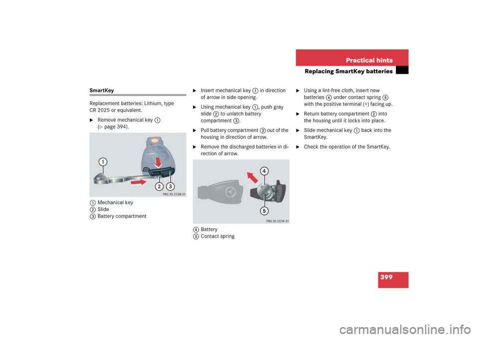
SmartKey
Replacement batteries: Lithium, type
CR 2025 or equivalent.�
Remove mechanical key1
(�page 394).
1Mechanical key
2Slide
3Battery compartment
�
Insert mechanical key1 in direction
of arrow in side opening.
�
Using mechanical key1, push gray
slide2 to unlatch battery
compartment3.
�
Pull battery compartment3 out of the
housing in direction of arrow.
�
Remove the discharged batteries in di-
rection of arrow.
4Battery
5Contact spring
�
Using a lint-free cloth, insert new
batteries4 under contact spring5
with the positive terminal (+) facing up.
�
Return battery compartment2 into
the housing until it locks into place.
�
Slide mechanical key1 back into the
SmartKey.
�
Check the operation of the SmartKey.
Page 405 of 481
�
Turn housing cover1 counterclock-
wise and remove.
�
Turn bulb socket5 with the bulb
counterclockwise and remove.
�
Pull the")
404 Practical hintsReplacing bulbsLow beam bulb (Halogen headlamps
only)�
Turn housing cover1 counterclock-
wise and remove.
�
Turn bulb socket5 with the bulb
counterclockwise and remove.
�
Pull the bulb out of bulb socket5.
�
Press the new bulb into bulb socket5.
�
Place bulb socket5 back into the
lamp and turn it clockwise.
�
Reinstall housing cover1.High beam/high beam flasher bulb
(Halogen headlamps) / High beam
flasher bulb (Bi-Xenon* headlamps)
�
Turn bulb socket3 with the bulb
counterclockwise and remove.
�
Pull the bulb out of bulb socket3.
�
Press the new bulb into bulb socket3.
�
Place bulb socket3 back into the
lamp and turn it clockwise.Front turn signal bulb
�
Turn bulb socket2 with the bulb
counterclockwise and remove.
�
Press gently onto the bulb and turn it
counterclockwise out of bulb
socket2.
�
Press the new bulb gently into bulb
socket2 and turn it clockwise.
�
Place bulb socket2 back into the
lamp and turn it clockwise.
Parking and standing lamp bulb
�
Turn bulb socket4 with the bulb
counterclockwise and remove.
�
Pull the bulb out of bulb socket4.
�
Press the new bulb into bulb socket4.
�
Place bulb socket4 back into the
lamp and turn it clockwise.
Page 406 of 481
405 Practical hints
Replacing bulbs
Replacing bulbs for rear lamps
Before you start to replace a bulb for a rear
lamp, do the following first:�
Turn the exterior lamp switch to
positionM (
�page 110).
�
Open the trunk lid (
�page 98).
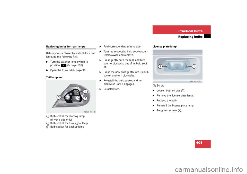
Tail lamp unit
1Bulb socket for rear fog lamp
(driver’s side only)
2Bulb socket for turn signal lamp
3Bulb socket for backup lamp
�
Fold corresponding trim to side.
�
Turn the respective bulb socket coun-
terclockwise and remove.
�
Press gently onto the bulb and turn
counterclockwise out of its bulb sock-
et.
�
Press the new bulb gently into its bulb
socket and turn clockwise.
�
Reinstall the bulb socket and turn
clockwise until it engages.
�
Reinstall trim.License plate lamp
1Screw
�
Loosen both screws1.
�
Remove the license plate lamp.
�
Replace the bulb.
�
Reinstall the license plate lamp.
�
Retighten screws1.
Page 414 of 481
.
�
Take the collapsible tire, wheel wrench,
wheel bolts, jack, and electric air pump
out of the trun")
413 Practical hints
Flat tire
Preparing the vehicle
Prepare the vehicle as described
(�page 408).
�
Take the collapsible tire, wheel wrench,
wheel bolts, jack, and electric air pump
out of the trunk (
�page 388).Lifting the vehicle
�
Prevent the vehicle from rolling away
by blocking wheels with wheel chocks
(not included) or other sizeable ob-
jects.
One wheel chock is included with the
vehicle tool kit (
�page 388).
When changing wheel on a level surface:
�
Place the wheel chock in front of and
another sizeable object behind the
wheel that is diagonally opposite to the
wheel being changed.
Always try lifting the vehicle using the jack
on a level surface. However, should cir-
cumstances require you to do so on a hill,
place the wheel chock and the other size-
able object as follows:
�
Place the wheel chock and another
sizeable object on the downhill side
blocking both wheels of the axle not
being worked on.
Drive to the nearest Mercedes-Benz Center
as soon as possible to have the spare wheel
with collapsible tire replaced with a regular
road wheel.
Never operate the vehicle with more than
one spare wheel with collapsible tire
mounted.
Do not switch off the ESP
® when a spare
wheel with collapsible tire is mounted.
Page 415 of 481
.
The jack ta")
414 Practical hintsFlat tire
1Wheel wrench�
On wheel to be changed, loosen but do
not yet remove the wheel bolts in direc-
tion of arrow (approximately one full
turn with wheel wrench1).
The jack take-up brackets are located di-
rectly behind the front wheel housings and
in front of the rear wheel housings.2Jack
3Take-up bracket
�
Place jack2 on firm ground.
�
Position jack2 under take-up
bracket3 so that it is always vertical
(plumb-line) as seen from the side,
even if the vehicle is parked on an
incline.
Warning!
G
The jack is designed exclusively for jacking
up the vehicle at the jack take-up brackets
built into either side of the vehicle. To help
avoid personal injury, use the jack only to lift
the vehicle during a wheel change. Never
get beneath the vehicle while it is supported
by the jack. Keep hands and feet away from
the area under the lifted vehicle. Always
firmly set parking brake and block wheels
before raising vehicle with jack.
Do not disengage parking brake while the
vehicle is raised. Be certain that the jack is
always vertical (plumb line) when in use, es-
pecially on hills. Always try to use the jack
o n l e v e l s u r f a c e . B e s u r e t h e j a c k a r m i s f u l l y
seated in the jack take-up bracket. Always
lower the vehicle onto sufficient capacity
jackstands before working under the
vehicle.
Warning!
G
Position the jack only on the jack take-up
brackets designed for this purpose.
If the jack is not properly positioned, the ve-
hicle may fall off of the jack.