Page 409 of 480
.
1Flap
2Air")
408 Practical hintsFlat tire�
Unscrew the alignment bolt, install last
wheel bolt and tighten slightly.Inflating the spare tire
�
Take the electric air pump out of the
trunk (
�page 383).
1Flap
2Air pump switch
3Electrical plug
4Air hose with pressure gauge and vent
screw
5Union nut
�
Open flap 1 on air pump.
�
Pull out electrical plug 3 and air hose
with the pressure gauge 4.
�
Remove the valve cap from the tire
valve.
�
Screw union nut 5 onto the tire valve.
�
Insert electrical plug 3 into vehicle ci-
gar lighter socket.
Damaged wheel hub threads should be re-
paired immediately. Do not continue to drive
under these circumstances! Contact an au-
thorized Mercedes-Benz Center or call
Roadside Assistance.
Incorrect wheel bolts or improperly tight-
ened wheel bolts can cause the wheel to
come off. This could cause an accident. Be
sure to use the correct wheel bolts.Warning!
G
Only use genuine equipment
Mercedes-Benz wheel bolts. They are identi-
fied by the Mercedes star. Other wheel bolts
may come loose.
Do not tighten the wheel bolts when the ve-
hicle is raised. Otherwise the vehicle could
fall off the jack.
!Do not lower the vehicle before inflat-
ing the spare wheel tire. Otherwise the
rim may be damaged.Warning!
G
Observe instructions on air pump label.
��
Page 411 of 480

410 Practical hintsFlat tire�
Detach the electric air pump.
�
Stow the electrical plug and the air
hose behind the flap and place the air
pump back in the trunk.Lowering the vehicle
�
Lower vehicle by turning crank coun-
terclockwise until the full weight of the
vehicle is resting on the ground.
�
Pull the jack out of the jack support
tube.
1 - 5 Wheel bolts
�
Tighten the five wheel bolts evenly, fol-
lowing the diagonal sequence illustrat-
ed (1 to 5), until all bolts are tight.
Observe a tightening torque of 96 lb-ft
(130 Nm).
Warning!
G
Follow recommend inflation pressures.
Do not overinflate tires. Overinflating tires
can result in sudden deflation (blowout) be-
cause they are more likely to become punc-
tured or damaged by road debris, potholes,
etc.
Do not underinflate tires. Underinflated tires
wear unevenly, adversely affect handling
and fuel economy, and are more likely to fail
from being overheated.
iThe flat tire may be transported in the
trunk when the retractable hardtop is
raised. Use the protective sheet provid-
ed with the spare wheel. Do not acti-
vate the tire inflation pressure monitor
until the deflated tire has been re-
moved from the vehicle.
��
Page 412 of 480

411 Practical hints
Flat tire
�
Before storing the jack in the trunk,
crank back to storage position and fold
in the arm.Replacing jack support tube cover
�
Slide tongue of cover under the upper
edge of the tube opening.
�
Applying even pressure, press cover
until it snaps into place.
Be careful not to damage the locking
tabs or clamp the plastic retaining
strap.
MOExtended system*
The MOExtended system allows you to
continue driving your vehicle even if there
is a total loss of pressure in one or more
tires.
You may only use the MOExtended system
in conjunction with the Run Flat Indicator*
(Canada vehicles) (
�page 293) or TPMS
(U.S. vehicles) (
�page 296).
Warning!
G
Have the tightening torque checked after
changing a wheel. The wheels could come
loose if they are not tightened to a torque of
96 lb-ft (130 Nm).Warning!
G
When turning the wheel wrench to tighten
the wheel bolts, make sure you position
hands on the wrench in such a way that you
avoid injury to yourself, such as scraping
your hands against the wheel. Make sure
turning the wheel wrench will not scratch or
damage the wheel rim.
!The maximum distance in emergency
mode depends on the vehicle’s load. It
is 30 miles (50 km) if the vehicle is par-
tially loaded and 18 miles (30 km) if the
vehicle is fully loaded.
The point at which the maximum driv-
ing distance begins in emergency
mode is when the warning message
appears in the multifunction display
indicating that there is a loss of tire
inflation pressure.
Do not exceed the maximum speed of
50 mph (80 km/h).
Page 414 of 480
413 Practical hints
Batteries
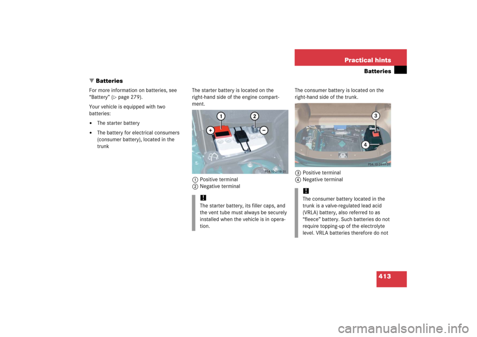
�Batteries
For more information on batteries, see
“Battery” (
�page 279).
Your vehicle is equipped with two
batteries:
�
The starter battery
�
The battery for electrical consumers
(consumer battery), located in the
trunkThe starter battery is located on the
right-hand side of the engine compart-
ment.
1Positive terminal
2Negative terminalThe consumer battery is located on the
right-hand side of the trunk.
3Positive terminal
4Negative terminal
!The starter battery, its filler caps, and
the vent tube must always be securely
installed when the vehicle is in opera-
tion.
!The consumer battery located in the
trunk is a valve-regulated lead acid
(VRLA) battery, also referred to as
“fleece” battery. Such batteries do not
require topping-up of the electrolyte
level. VRLA batteries therefore do not
Page 417 of 480
.
�
Unhook the luggage cover in the trunk.
�
Remove")
416 Practical hintsBatteries�
Depress the parking brake pedal.
�
Open the trunk.
�
Read and observe safety instructions
and precautions (
�page 279).
�
Unhook the luggage cover in the trunk.
�
Remove the trunk floor.
The battery for electrical consumers is
located in the right hand area of the
trunk (
�page 383).
�
Use the 10 mm open-end wrench from
the vehicle tool kit to disconnect the
negative lead from negative
terminal4 of the consumer battery
(�page 413).
�
Open the hood (
�page 272).
�
Use the 10 mm open-end wrench from
the vehicle tool kit to disconnect the
negative lead from negative
terminal2 of the starter battery
(�page 413).
�
Remove the covers from the positive
terminals 1 and 3 (
�page 413).
�
Disconnect the positive lead from pos-
itive terminal 3 of the consumer bat-
tery (
�page 413).
�
Disconnect the positive lead from pos-
itive terminal 1 of the starter battery
(�page 413).
Removing the batteries
Removing the consumer battery�
Remove the screws securing the bat-
tery in the trunk.
�
Remove the battery support and
bracket.
�
Pull out the battery ventilation tube
from the battery.
Depending on battery arrangement in
your vehicle model, the ventilation tube
is located either on the left or right side
of the battery.
�
Take out the battery.
��
Page 419 of 480
418 Practical hintsBatteriesReconnecting the batteries�
Turn off all electrical consumers.
�
Install starter battery in the designated
location in the engine compartment.
�
Install consumer battery in the desig-
nated location in the trunk.
�
Attach supports and brackets.
�
Tighten support and bracket screws.
�
Connect positive lead 3 of the con-
sumer battery and positive lead 1 of
the starter battery and fasten covers.
�
Connect negative lead 2 of the starter
battery.
�
Connect negative lead 4 of the con-
sumer battery.
�
Reinstall the trunk floor.
�
Rehook trunk luggage cover into hold-
ers.
!Always connect the batteries in the
order described below. Otherwise the
vehicle’s electronics can be damaged.!Never invert the terminal connections!
iThe following procedures must be car-
ried out following any interruption of
battery power (e.g. due to reconnec-
tion):�
Resynchronize the ESP
®
(
�page 354).
�
Resynchronize side windows
(�page 194).
Page 424 of 480

423 Practical hints
Towing the vehicle
Installing towing eye bolt
Front of vehicle
1Cover on right side of front bumper
To remove cover:�
Press mark on cover 1 in direction of
arrow.
�
Lift cover1off to reveal the threaded
hole for towing eye bolt.
The towing eye bolt is supplied with the
tool kit (located in the storage compart-
ment under the trunk floor).
!When towing the vehicle with all wheels
on the ground, please note the follow-
ing:
With the automatic central locking acti-
vated and the SmartKey in starter
switch position2, or KEYLESS-GO*
start/stop button in position2, the ve-
hicle doors lock if the left front wheel
as well as the right rear wheel are turn-
ing at vehicle speeds of approx. 9 mph
(15 km / h) or more.
To prevent the vehicle door locks from
locking, deactivate the automatic cen-
tral locking (
�page 112).
Towing of the vehicle should only be
done using the properly installed tow-
ing eye bolt. Never attach tow cable,
tow rope or tow rod to the vehicle chas-
sis, frame or suspension parts.
iIf the battery is disconnected or dis-
charged�
the SmartKey will not turn in the
starter switch
�
the gear selector lever will remain
locked in positionP.
For more information, see “Batteries”
(
�page 413) and
“Jump starting” (
�page 419).
��
Page 425 of 480
424 Practical hintsTowing the vehicle�
Screw towing eye bolt in to its stop and
tighten with lug wrench.
To reinstall cover:
�
Fit locking tabs of cover under the low-
er edge of the opening in the bumper.
�
Apply even pressure on the upper part
of the cover until it snaps into place.
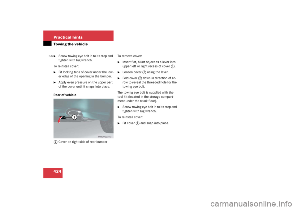
Rear of vehicle
2Cover on right side of rear bumperTo remove cover:
�
Insert flat, blunt object as a lever into
upper left or right recess of cover 2.
�
Loosen cover 2 using the lever.
�
Fold cover 2 down in direction of ar-
row to reveal the threaded hole for the
towing eye bolt.
The towing eye bolt is supplied with the
tool kit (located in the storage compart-
ment under the trunk floor).
�
Screw towing eye bolt in to its stop and
tighten with lug wrench.
To reinstall cover:
�
Fit cover 2 and snap into place.
��