Page 416 of 480
.
�
Turn off the engine (
�page 60).
�
T")
415 Practical hints
Batteries
Disconnecting the batteries�
Make sure the gear selector lever is set
to position P.
�
Close the retractable hardtop
(�page 195).
�
Turn off the engine (
�page 60).
�
Turn off all electrical consumers.
�
Remove the SmartKey from the starter
switch.
or
�
Vehicles with KEYLESS-GO*: Open the
driver’s door.
Warning!
G
The brake system requires electrical power
to operate.
A malfunction in the vehicle’s power supply
or electrical system may impair brake sys-
tem operation and switch it into its emer-
gency operation mode. The same applies if
battery is disconnected. To brake, the driver
must then apply significantly greater brake
pedal pressure and depress the pedal much
further to obtain the expected braking ef-
fect. If necessary, apply full pressure to the
brake pedal. Brakes are only applied to the
front wheels. Stopping distance is in-
creased! Adjust your driving style according-
ly. For more information, see
“Electro-hydraulic brake system”
(�page 88).
Warning!
G
With a disconnected battery�
you will no longer be able to turn the
SmartKey in the starter switch and
pressing the KEYLESS-GO* start/stop
button on the gear selector lever will
have no effect
�
the gear selector lever will remain
locked in positionP
!Always disconnect the batteries in the
order described below, even if you only
want to charge the starter battery, for
example. Otherwise the vehicle’s
electronics can be damaged.
��
Page 417 of 480
.
�
Unhook the luggage cover in the trunk.
�
Remove")
416 Practical hintsBatteries�
Depress the parking brake pedal.
�
Open the trunk.
�
Read and observe safety instructions
and precautions (
�page 279).
�
Unhook the luggage cover in the trunk.
�
Remove the trunk floor.
The battery for electrical consumers is
located in the right hand area of the
trunk (
�page 383).
�
Use the 10 mm open-end wrench from
the vehicle tool kit to disconnect the
negative lead from negative
terminal4 of the consumer battery
(�page 413).
�
Open the hood (
�page 272).
�
Use the 10 mm open-end wrench from
the vehicle tool kit to disconnect the
negative lead from negative
terminal2 of the starter battery
(�page 413).
�
Remove the covers from the positive
terminals 1 and 3 (
�page 413).
�
Disconnect the positive lead from pos-
itive terminal 3 of the consumer bat-
tery (
�page 413).
�
Disconnect the positive lead from pos-
itive terminal 1 of the starter battery
(�page 413).
Removing the batteries
Removing the consumer battery�
Remove the screws securing the bat-
tery in the trunk.
�
Remove the battery support and
bracket.
�
Pull out the battery ventilation tube
from the battery.
Depending on battery arrangement in
your vehicle model, the ventilation tube
is located either on the left or right side
of the battery.
�
Take out the battery.
��
Page 418 of 480

417 Practical hints
Batteries
Removing the starter battery�
Remove the screws securing the start-
er battery in the engine compartment.
�
Pull out the battery ventilation tube
from the battery.
Depending on battery arrangement in
your vehicle model, the ventilation tube
is located either on the left or right side
of the battery.
�
Lift the retaining bracket.
�
Remove the battery.
Charging and reinstalling batteries�
Charge batteries in accordance with
the instructions of the battery charger
manufacturer.
�
Reinstall the charged batteries. Follow
the previously described steps in re-
verse order.
Warning!
G
Never charge a battery while still installed in
the vehicle unless the accessory battery
charge unit approved by Mercedes-Benz is
being used. Gases may escape during charg-
ing and cause explosions that may result in
paint damage, corrosion or personal injury.
An accessory battery charge unit specially
adapted for Mercedes-Benz vehicles and
tested and approved by Mercedes-Benz is
available, permitting the charging of the bat-
tery in its installed position. Contact an au-
thorized Mercedes-Benz Center for
information and availability. Charge battery
in accordance with the separate instruc-
tions for the accessory battery charger.
Page 419 of 480
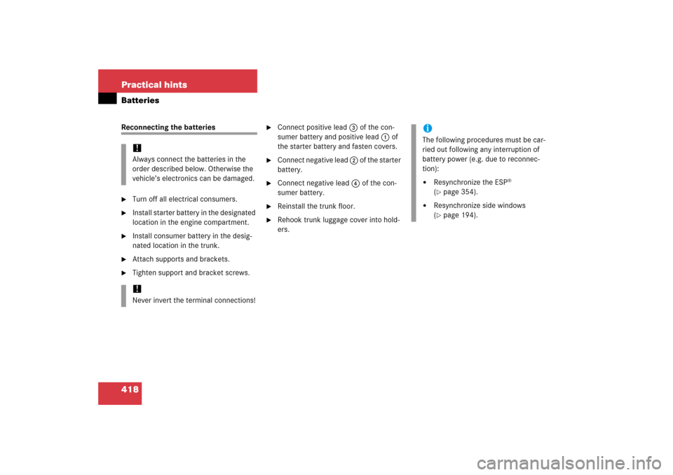
418 Practical hintsBatteriesReconnecting the batteries�
Turn off all electrical consumers.
�
Install starter battery in the designated
location in the engine compartment.
�
Install consumer battery in the desig-
nated location in the trunk.
�
Attach supports and brackets.
�
Tighten support and bracket screws.
�
Connect positive lead 3 of the con-
sumer battery and positive lead 1 of
the starter battery and fasten covers.
�
Connect negative lead 2 of the starter
battery.
�
Connect negative lead 4 of the con-
sumer battery.
�
Reinstall the trunk floor.
�
Rehook trunk luggage cover into hold-
ers.
!Always connect the batteries in the
order described below. Otherwise the
vehicle’s electronics can be damaged.!Never invert the terminal connections!
iThe following procedures must be car-
ried out following any interruption of
battery power (e.g. due to reconnec-
tion):�
Resynchronize the ESP
®
(
�page 354).
�
Resynchronize side windows
(�page 194).
Page 420 of 480

419 Practical hints
Jump starting
�Jump starting
If the starter battery is discharged, the en-
gine can be started with jumper cables and
the battery of another vehicle. Observe the
following:�
Jump starting should only be performed
when the engine and catalytic convert-
er are cold.
�
Do not start the engine if the battery is
frozen. Let the battery thaw out first.
�
Only jump start from batteries with the
same voltage rating (12 V). Jump start-
ing with a more powerful battery could
damage the vehicle’s electrical system,
which will not be covered by the
Mercedes-Benz Limited Warranty.
�
Only use jumper cables with sufficient
cross section and insulated terminal
clamps.
�
Always make sure the jumper cables
are not on or near pulleys, fans, or oth-
er parts that move when an engine is
started or running.
Warning!
G
Failure to follow these directions will cause
damage to the electronic components, and
can lead to a battery explosion and severe
injury or death.
Never lean over batteries while connecting
or jump starting, you might get injured.
Battery fluid contains sulfuric acid. Do not
allow this fluid to come in contact with eyes,
skin or clothing. In case it does, immediately
flush affected area with water, and seek
medical help if necessary.
A battery will also produce hydrogen gas,
which is flammable and very explosive. Keep
flames or sparks away from battery, avoid
improper connection of jumper cables,
smoking, etc.
Attempting to jump start a frozen battery
can result in it exploding, causing personal
injury.
Read all instructions before proceeding.
!Jump starting may only be performed
on the battery installed in the engine
compartment.
Avoid repeated and lengthy starting at-
tempts.
Do not attempt to start the engine us-
ing a battery quick charge unit.
If the engine does not run after several
unsuccessful starting attempts, have it
checked at the nearest authorized
Mercedes-Benz Center.
Excessive unburned fuel generated by
repeated failed starting attempts may
damage the catalytic converter and
may present a fire risk.
Make sure the jumper cables do not
have loose or missing insulation.
Make sure the cable clamps do not
touch any other metal part while the
other end is still attached to a battery.
Page 421 of 480

420 Practical hintsJump startingThe starter battery is located on the right
side of the engine compartment.�
Make sure the two vehicles do not
touch.
�
Turn off all electrical consumers.
�
Apply the parking brake (
�page 59).
�
Shift gear selector lever to positionP.
�
Open the hood (
�page 272).
�
Remove the red cover from positive ter-
minal on both vehicles (
�page 413).1Negative terminal of charged battery
2Negative terminal of discharged
battery
3Positive terminal of discharged battery
4Positive terminal of charged battery
�
Connect positive terminals 3 and 4
of the batteries with the jumper cables.
Clamp cable to charged battery 4
first.
�
Start the engine of the vehicle with the
charged battery and run at idle speed.
�
Connect negative terminals 1 and 2
of the batteries with the jumper cables.
Clamp cable to charged battery 1
first.
�
Start the engine of the disabled vehi-
cle.
You can now turn on the electrical con-
sumers. Do not turn on the lights under
any circumstances.
�
Remove the jumper cables first from
negative terminals 2 and 1 and then
from positive terminals 3 and 4.
You can now turn on the lights.
�
Have the battery checked at the near-
est Mercedes-Benz Center.
Warning!
G
Keep flames or sparks away from battery.
Do not smoke.
Observe all safety instructions and precau-
tions when handling automotive batteries
(�page 279).
!Never invert the terminal connections.
!Do not tow-start the vehicle.
Page 424 of 480

423 Practical hints
Towing the vehicle
Installing towing eye bolt
Front of vehicle
1Cover on right side of front bumper
To remove cover:�
Press mark on cover 1 in direction of
arrow.
�
Lift cover1off to reveal the threaded
hole for towing eye bolt.
The towing eye bolt is supplied with the
tool kit (located in the storage compart-
ment under the trunk floor).
!When towing the vehicle with all wheels
on the ground, please note the follow-
ing:
With the automatic central locking acti-
vated and the SmartKey in starter
switch position2, or KEYLESS-GO*
start/stop button in position2, the ve-
hicle doors lock if the left front wheel
as well as the right rear wheel are turn-
ing at vehicle speeds of approx. 9 mph
(15 km / h) or more.
To prevent the vehicle door locks from
locking, deactivate the automatic cen-
tral locking (
�page 112).
Towing of the vehicle should only be
done using the properly installed tow-
ing eye bolt. Never attach tow cable,
tow rope or tow rod to the vehicle chas-
sis, frame or suspension parts.
iIf the battery is disconnected or dis-
charged�
the SmartKey will not turn in the
starter switch
�
the gear selector lever will remain
locked in positionP.
For more information, see “Batteries”
(
�page 413) and
“Jump starting” (
�page 419).
��
Page 443 of 480
442 Technical dataElectrical systemModel
SL 500
SL 600
SL 55 AMG
SL 65 AMG
Generator (alternator)
14 V/150 A
14 V/180 A
14 V/180 A
14 V/180 A
Starter motor
12 V/1.7 kW
12 V/1.7 kW
12 V/1.7 kW
12 V/1.7 kW
BatteryStarter battery
12 V/35 Ah
12 V/35 Ah
12 V/35 Ah
12 V/35 Ah
Battery for electrical consumers
12 V/70 Ah
12 V/70 Ah
12 V/70 Ah
12 V/70 Ah
Spark plugs
Bosch F 8 DPP 33
NGK PFR5R11
NGK IFR6QG
NGK ILFR6A
NGK IFR6QG
Electrode gap
0.039 in (1.0 mm)
0.028 in (0.7 mm)
0.031 in (0.8 mm)
0.028 in (0.7 mm)
Tightening torque
15 – 22 lb-ft
(20 – 30 Nm)
18 – 22 lb-ft
(25 – 30 Nm)
18 – 22 lb-ft
(25 – 30 Nm)
18 – 22 lb-ft
(25 – 30 Nm)

14 V/150 A
14 V/180 A
14 V/180 A
14 V/180 A
Starter motor
12 V/1.7 kW
12 V/1.7 kW
12 V/1.7 kW
12 V/1.7")