Page 373 of 481

372 Practical hintsWhat to do if …?Display
Possible cause
Possible solution
.
STANDING LIGHT, L
CHECK LIGHT
The left front parking lamp is malfunction-
ing.
�
Replace the bulb as soon as possible.
STANDING LIGHT, R
CHECK LIGHT
The right front parking signal lamp is mal-
functioning.
�
Replace the bulb as soon as possible.
STANDING LIGHT, L
CHECK LIGHT
SUBSTITUTE LAMP ON
The left rear parking signal lamp is mal-
functioning. A substitute bulb is being
used.
�
Replace the bulb as soon as possible.
STANDING LIGHT, R
CHECK LIGHT
SUBSTITUTE LAMP ON
The right rear parking signal lamp is mal-
functioning. A substitute bulb is being
used.
�
Replace the bulb as soon as possible.
TAIL LIGHT, LEFT
CHECK LIGHT
SUBSTITUTE LAMP ON
The left tail lamp is malfunctioning. A sub-
stitute bulb is being used.
�
Replace the bulb as soon as possible.
TAIL LIGHT, RIGHT
CHECK LIGHT
SUBSTITUTE LAMP ON
The right tail lamp is malfunctioning. A
substitute bulb is being used.
�
Replace the bulb as soon as possible.
TURN OFF LIGHTS
Lamps have been turned on although the
SmartKey in the ignition is in position 0.
�
Turn the exterior lamp switch to M
(�page 50).
Page 374 of 481

373 Practical hints
What to do if …?
Display
Possible cause
Possible solution
.
FRONT TURN SIGNAL, L
CHECK LIGHT
The left front turn signal lamp is malfunc-
tioning.
�
Replace the bulb as soon as possible.
FRONT TURN SIGNAL, R
CHECK LIGHT
The right front turn signal lamp is malfunc-
tioning.
�
Replace the bulb as soon as possible.
REAR TURN SIGNAL, L
CHECK LIGHT
SUBSTITUTE LAMP ON
The left rear turn signal lamp is malfunc-
tioning. A substitute bulb is being used.
�
Replace the bulb as soon as possible.
REAR TURN SIGNAL, R
CHECK LIGHT
SUBSTITUTE LAMP ON
The right rear turn signal lamp is malfunc-
tioning. A substitute bulb is being used.
�
Replace the bulb as soon as possible.
MIRROR TURN SIG., L
CHECK LIGHT
The left turn signal in the side mirror is
malfunctioning. This message will only ap-
pear if all light emitting diodes have
stopped working.
�
Visit an authorized Mercedes-Benz Cen-
ter as soon as possible.
MIRROR TURN SIG., R
CHECK LIGHT
The right turn signal in the side mirror is
malfunctioning. This message will only ap-
pear if all light emitting diodes have
stopped working.
�
Visit an authorized Mercedes-Benz Cen-
ter as soon as possible.
Page 392 of 481
391 Practical hints
Opening/closing in an emergency
�Opening/closing in an emergency
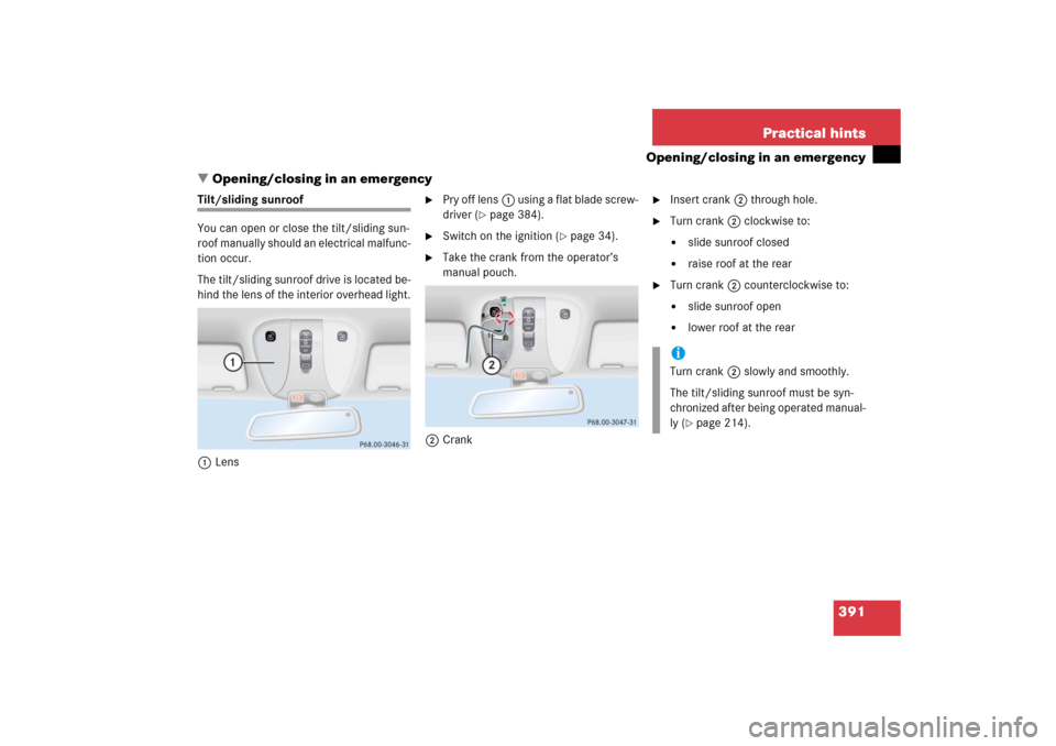
Tilt/sliding sunroof
You can open or close the tilt/sliding sun-
roof manually should an electrical malfunc-
tion occur.
The tilt/sliding sunroof drive is located be-
hind the lens of the interior overhead light.
1Lens
�
Pry off lens1 using a flat blade screw-
driver (
�page 384).
�
Switch on the ignition (
�page 34).
�
Take the crank from the operator’s
manual pouch.
2Crank
�
Insert crank2 through hole.
�
Turn crank2 clockwise to:�
slide sunroof closed
�
raise roof at the rear
�
Turn crank2 counterclockwise to:�
slide sunroof open
�
lower roof at the rear
iTurn crank2 slowly and smoothly.
The tilt/sliding sunroof must be syn-
chronized after being operated manual-
ly (
�page 214).
Page 394 of 481

393 Practical hints
Replacing SmartKey batteries
4Battery
5Contact spring�
Remove the batteries4 in the direc-
tion of arrow.
�
Using a lint-free cloth, insert new
batteries4 under the contact
spring5 with the positive terminal (+)
side facing up.
�
Return battery compartment3
(�page 392) into housing until it locks
into place.
�
Slide mechanical key1 (
�page 388)
back into the SmartKey.
�
Check the operation of the SmartKey.
SmartKey with KEYLESS-GO*
Replacement battery: Lithium, type
CR 2025 or equivalent.�
Remove the mechanical key out of the
SmartKey with KEYLESS-GO
(�page 388).
�
Remove battery compartment3
(�page 392) out of the housing.
1Battery
2Tilt battery up
3Mechanical key
�
Using mechanical key3, apply pres-
sure to position2.
Battery1 tilts up slightly.
�
Pull out battery1 in the direction of
arrow.
�
Using a lint-free cloth, insert new
battery1 with the plus (+) side facing
up.
�
Return battery compartment3
(�page 392) into housing until it locks
into place.
�
Slide mechanical key1 (
�page 388)
back into the SmartKey with
KEYLESS-GO.
�
Check the operation of KEYLESS-GO.
Page 395 of 481
394 Practical hintsReplacing bulbsSafe vehicle operation depends on proper
exterior lighting and signaling. It is there-
fore essential that all bulbs and lamp as-
semblies are in good working order at all
times.
Correct headlamp adjustment is extremely
important. Have headlamps checked and
readjusted at regular intervals and when a
bulb has been replaced. See an authorized
Mercedes-Benz Center for headlamp ad-
justment.
iIf the headlamps or front fog lamps are
fogged up on the inside as a result of
high humidity, driving the vehicle a dis-
tance with the lights on should clear up
the fogging.
iSubstitute bulbs will be brought into
use when the following lamps malfunc-
tion:�
Brake lamps
�
Rear parking lamps
�
Rear turn signal lamps
�
Tail lamps
Observe the messages in the multi-
function display (
�page 369).
Page 397 of 481

396 Practical hintsReplacing bulbsNotes on bulb replacement
�
Only use 12-volt-bulbs of the same
type and with the specified watt rating.
�
Switch lights off before changing a bulb
to prevent short circuits.
�
Always use a clean lint-free cloth when
handling bulbs.
�
Your hands should be dry and free of oil
and grease.
�
If the newly installed bulb does not
come on, visit an authorized
Mercedes-Benz Center.Have the LEDs and bulbs for the following
lamps replaced by an authorized
Mercedes-Benz Center.
�
Additional turn signal lamps in the exte-
rior rear view mirrors
�
Bi-Xenon lamps*
�
High mounted brake lamp
�
Brake lamps
�
Rear side marker lamps
�
Rear parking lamps
Warning!
G
Keep bulbs out of reach of children.
Bulbs and bulb sockets can be very hot. Al-
low the lamp to cool down before changing
a bulb.
Halogen lamps contain pressurized gas. A
bulb can explode if you:�
touch or move it when hot
�
drop the bulb
�
scratch the bulb
Wear eye and hand protection.
Because of high voltage in Xenon lamps, it is
dangerous to replace the bulb or repair the
lamp and its components. We recommend
that you have such work done by a qualified
technician.
iHave the headlamp adjustment
checked regularly.
Page 408 of 481

407 Practical hints
Flat tire
�
Guide the spare wheel onto the align-
ment bolt and push it on.
�
Insert wheel bolts and tighten them
slightly.
�
Unscrew the alignment bolt, install last
wheel bolt and tighten slightly.
Lowering the vehicle
�
Lower vehicle by turning crank coun-
terclockwise until vehicle is resting ful-
ly on its own weight.
�
Remove the jack.1 - 5 Wheel bolts
�
Tighten the five wheel bolts evenly, fol-
lowing the diagonal sequence illustrat-
ed (1 to 5), until all bolts are tight.
Observe a tightening torque of
110 lb-ft (150 Nm).
�
Before storing the jack in the trunk, it
should be fully collapsed, with handle
folded in.
�
Place the wheel bolt wrench, alignment
bolt and jack back in the vehicle tool kit
in the trunk and close the covering lid.
Replacing jack support tube cover
�
Slide tongue of cover under the upper
edge of the tube opening.
�
Applying even pressure, press cover
until it snaps into place. Be careful not
to damage the locking tabs or clamp
the plastic retaining strap.
Warning!
G
Use only genuine equipment
Mercedes-Benz wheel bolts. Other wheel
bolts may come loose.
Do not tighten the wheel bolts when the ve-
hicle is raised. Otherwise the vehicle could
fall off the jack.
Warning!
G
Have the tightening torque checked after
changing a wheel. The wheels could come
loose if they are not tightened to a torque of
110 lb-ft (150 Nm).
!You can also store and secure the dam-
aged wheel in the spare wheel well in
the trunk.
Do not activate the tire inflation pres-
sure monitor* until the depressurized
tire is no longer in the vehicle.
Page 413 of 481
.
�
Make sure the two vehicles do not
touch.
�
Turn off all electrical consu")
412 Practical hintsJump startingThe battery is located on the right side of
the trunk under the battery cover
(�page 408).
�
Make sure the two vehicles do not
touch.
�
Turn off all electrical consumers.
�
Apply parking brake.
�
Shift gear selector lever to positionP.
�
Open the trunk lid.
�
Remove battery cover (
�page 408).
�
Remove red cover from positive
terminal 1. 1Positive terminal of discharged battery
2Negative terminal of discharged
battery
3Positive terminal of charged battery
4Negative terminal of charged battery
�
Connect positive terminals 1 and3
of the batteries with the jumper cable.
Clamp cable to charged battery3
first.
�
Start engine of the vehicle with the
charged battery and run at idle speed.
�
Connect negative terminals2 and4
of the batteries with the jumper cable.
Clamp cable to charged battery4
first.
�
Start the engine of the disabled vehi-
cle.
Now you can again turn on the electrical
consumers. Do not turn on the lights under
any circumstances.
�
Remove the jumper cables first from
negative terminals2 and4 and then
from positive terminals1 and3.
You can now turn on the lights.
�
Have the battery checked at the near-
est authorized Mercedes-Benz Center.
Warning!
G
Keep flames or sparks away from battery.
Do not smoke.
Observe all safety instructions and precau-
tions when handling automotive batteries
(�page 408).
!Never invert the terminal connections.