Page 233 of 481
*
The ABC system automatically selects the
optimum suspension tuning and ride
height for your vehicle.
Suspension tuning
The suspension")
232 Controls in detailDriving systemsActive Body Control (ABC)*
The ABC system automatically selects the
optimum suspension tuning and ride
height for your vehicle.
Suspension tuning
The suspension tuning is set according to:�
your driving style
�
road surface conditions
�
the vehicle loading
�
your choice of suspension style
You can set following suspension style:
�
regular (convenience)
�
sportyThe ABC button with the indicator lamps is
located on the upper part of the front cen-
ter console.
1Indicator lamp
2ABC button
�
Start the engine.
Suspension for sporty driving style
The setting for sporty driving is selected
when indicator lamp1 is illuminated.
�
Press button2.
Indicator lamp1 comes on.The message:
ACTIVE BODY CONTROL
ABC
SPORTSappears in the multifunction display for
a short time.
Suspension for regular driving style
The setting for regular driving is selected
when indicator lamp1 is off.
�
Press button2.
Indicator lamp1 goes out.
The message:ACTIVE BODY CONTROL
ABC
CONVENIENCEappears in the multifunction display for
a short time.
iThe selected setting is stored, even if
the engine is turned off.
Page 234 of 481

233 Controls in detail
Driving systems
Vehicle level control with ABC*
Your vehicle automatically adjusts its ride
height to:
�
reduce fuel consumption
�
increase vehicle safety
The vehicle chassis ride height is raised or
lowered according to the selected level
setting and to the vehicle speed:
�
With increasing speed, ride height is re-
duced by up to approximately 1.4 in
(35 mm).
�
With decreasing speed, the ride height
is again raised to the selected vehicle
level.Select the level 1 and 2 settings only when
required by current driving conditions.
Otherwise:
�
Fuel consumption may increase.
�
Handling may be impaired.
The following vehicle level settings can be
selected when the vehicle is stationary:
Warning!
G
To help avoid personal injury, keep hands
and feet away from wheel housing area, and
stay away from under the vehicle when low-
ering the vehicle chassis.
iThese height adjustments are so small
that you may not notice any change.
Vehicle level
when stationary
Use for
Ride height increase
over normal
Automatic lowering
Indicator lamps
Normal
Normal operation
None
Max. approx. 0.6 in (15 mm)
Both lamps off
Level1
Driving with snow chains
(�page 328)
Max. 0.4 in (10 mm)
1
1Dependent on load
Max. approx. 1.0 in (25 mm)
One lamp lit
Level 2
Very rough road surface
conditions
Max. 0.8 in (20 mm)
1
Max. approx. 1.4 in (35 mm)
Both lamps lit
Page 235 of 481
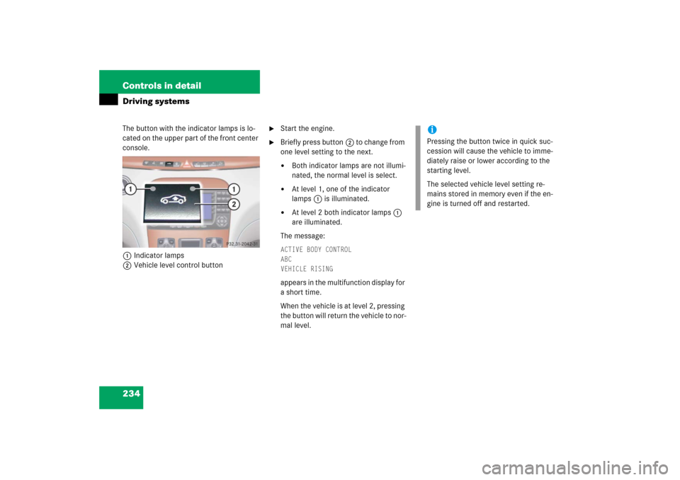
234 Controls in detailDriving systemsThe button with the indicator lamps is lo-
cated on the upper part of the front center
console.
1Indicator lamps
2Vehicle level control button
�
Start the engine.
�
Briefly press button2 to change from
one level setting to the next. �
Both indicator lamps are not illumi-
nated, the normal level is select.
�
At level 1, one of the indicator
lamps1 is illuminated.
�
At level 2 both indicator lamps1
are illuminated.
The message:
ACTIVE BODY CONTROL
ABC
VEHICLE RISINGappears in the multifunction display for
a short time.
When the vehicle is at level 2, pressing
the button will return the vehicle to nor-
mal level.
iPressing the button twice in quick suc-
cession will cause the vehicle to imme-
diately raise or lower according to the
starting level.
The selected vehicle level setting re-
mains stored in memory even if the en-
gine is turned off and restarted.
Page 266 of 481
.
Step 2:
�
If you have previously programmed an
integra")
265 Controls in detail
Useful features
Programming or reprogramming the in-
tegrated remote control
Step 1:�
Switch on the ignition (
�page 34).
Step 2:
�
If you have previously programmed an
integrated signal transmitter button
and wish to retain its programming,
proceed to step 3. Otherwise, press
and hold the two outer signal transmit-
ter buttons2 and 4 and release
them only when the indicator lamp1
begins to flash after approximately
20 seconds (do not hold the button for
longer than 30 seconds). This proce-
dure erases any previous settings for
all three channels and initializes the
memory. If you later wish to program a
second and/or third hand-held trans-
mitter to the remaining two signal
transmitter buttons, do not repeat this
step and begin directly with step 3.Step 3:
�
Hold the end of the hand-held remote
control transmitter6 of the device
you wish to train approximately 2 to
5 in (5 to 12 cm) away from the surface
of the integrated remote control locat-
ed on the interior rear view mirror,
keeping the indicator lamp1 in view.
Step 4:
�
Using both hands, simultaneously
press the hand-held transmitter
button5 and the desired integrated
signal transmitter button (2, 3
or4). Do not release the buttons until
completing step 5.
The indicator lamp1 on the integrat-
ed remote control will flash, first slowly
and then rapidly.Step 5:
�
When the indicator lamp 1 flashes
rapidly, release both buttons.
Step 6:
�
Press and hold the just-trained inte-
grated signal transmitter button and
observe the indicator lamp1.
If the indicator lamp1 stays on con-
stantly, programming is complete and
your device should activate when the
integrated signal transmitter button is
pressed and released.iThe indicator lamp1 flashes the first
time the signal transmitter button is
programmed. If this button has already
been programmed, the indicator lamp
will only start flashing after 20 sec-
onds.
��
Page 310 of 481
.
�
Press buttonè orÿ on the mul-
tifunction steering wheel repeatedly
until the standard display menu
appears in the multifuncti")
309 Operation
Tires and wheels
�
Switch on the ignition (
�page 34).
�
Press buttonè orÿ on the mul-
tifunction steering wheel repeatedly
until the standard display menu
appears in the multifunction display
(�page 143).
�
Press buttonj ork repeatedly
until the current tire inflation pressures
for each tire appear in the multifunc-
tion display.
iAfter you have reactivated the tire infla-
tion pressure monitor, the current tire
inflation pressures will only be shown
after a few minutes’ driving time.
During this time, you will see the follow-
ing message in the multifunction dis-
play:TIRE PRES. DISPLAY
APPEARS AFTER
DRIVING A FEW
MINUTESiPossible differences between the
readings of a tire inflation pressure
gauge of an air hose, e.g. gas station
equipment, and the vehicle’s control
system can occur. The readings issued
by the control system are more pre-
cise.
iYou can select the unit of measure
(Bar/Psi) used for the tire inflation
pressure by changing the setting in the
control system (
�page 164).
Warning!
G
When the tire inflation pressure monitoring
system warning light is lit, one or more of
your tires is significantly under-inflated. You
should stop and check your tires as soon as
possible, and inflate them to the proper tire
inflation pressure as indicated on the vehi-
cle’s tire information placard. Driving on a
significantly under-inflated tire causes the
tire to overheat and can lead to tire failure.
Under-inflation also reduces fuel efficiency
and tire tread life, and may affect the vehi-
cle’s handling and stopping ability. Each tire,
including the spare, should be checked
monthly when cold and set to the recom-
mended tire inflation pressure as specified
in the vehicle placard and owner’s manual.
Page 329 of 481

The engine is equipped with a block
heater.
The electrical cable may be installed at an
authorized Mercedes-Benz Center.Snow chains
Snow chains")
328 OperationWinter drivingBlock heater (Canada only)
The engine is equipped with a block
heater.
The electrical cable may be installed at an
authorized Mercedes-Benz Center.Snow chains
Snow chains should only be driven on
snow-covered roads at speeds not to
exceed 30 mph (50 km/h). Remove chains
as soon as possible when driving on roads
without snow.Please observe the following guidelines
when using snow chains:
�
Use of snow chains is not permissible
with all wheel/tire combinations.
�
Snow chains should only be used on
the rear wheels. Follow the manufac-
turer’s mounting instructions.
�
Only use snow chains that are
approved by Mercedes-Benz. Your
authorized Mercedes-Benz Center will
be glad to advise you on this subject.
�
Use of snow chains may be prohibited
depending on location. Always check
local and state laws before installing
snow chains.
iWhen driving with snow chains, you
may wish to deactivate the ESP
®
(
�page 82) before setting the vehicle
in motion. This will improve the
vehicle’s traction.
!Even on vehicles with all-wheel-drive
use snow chains on rear tires only.
Some tire sizes do not leave adequate
clearance for snow chains. To help
avoid serious damage to your vehicle or
tires, use of snow chains is not permis-
sible with the following tire sizes: �
245/45 R18 100V XL (Extra Load)
M+S.on 8
1/2 x 18 rims
�
245/45 R18 96H M+S.on
81/2x 18 rims
�
245/45 R18 100Y XL (Extra Load)
on 8
1/2 x 18 rims
�
245/45 R18 96Y on 8
1/2 x 18 rims
�
265/40 R18 101Y XL (Extra Load)
�
265/40 R18 97Y
�
245/40 ZR19 98Y XL (Extra Load)
�
245/40 ZR19
�
275/35 ZR19 100Y XL (Extra Load)
�
275/35 ZR19
Page 332 of 481
331 Operation
Maintenance
Resetting the maintenance service indi-cator
In the event that the maintenance service
on your vehicle is not carried out by an au-
thorized Mercedes-Benz Center, you can
have the maintenance service indicator re-
set. The automotive maintenance facility
carrying out the maintenance service will
find the information for resetting the main-
tenance service indicator in the mainte-
nance-relevant information for your
vehicle. Such information is available from
either your authorized Mercedes-Benz
Center or directly from Mercedes-Benz
USA, LLC.
iIf the maintenance service indicator
was inadvertently reset, have an autho-
rized Mercedes-Benz Center correct it.
Only reset if the proper maintenance
service has been performed. Resetting
the system without performing the
proper service as called for by the
maintenance service indicator will re-
sult in engine damage and/or other ve-
hicle damage not covered by the
Mercedes-Benz Limited Warranty.
Page 402 of 481
401 Practical hints
Replacing wiper blades
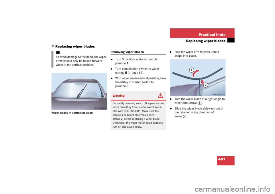
�Replacing wiper blades
Wiper blades in vertical position
Removing wiper blades�
Turn SmartKey in starter switch
position1.
�
Turn combination switch to wiper
settingII (
�page 52).
�
With wiper arm in vertical position, turn
SmartKey in starter switch to
position0.
�
Fold the wiper arm forward until it
snaps into place.
�
Turn the wiper blade at a right angle to
wiper arm (arrow 1).
�
Slide the wiper blade sideways out of
the retainer in the direction of
arrow2.
!To avoid damage to the hood, the wiper
arms should only be folded forward
when in the vertical position.
Warning!
G
For safety reasons, switch off wipers and re-
move SmartKey from starter switch (vehi-
cles with KEYLESS-GO*: Make sure the
vehicle’s on-board electronics have
status0) before replacing a wiper blade.
Otherwise, the wiper motor could suddenly
turn on and cause injury.