Page 123 of 561
122 Controls in detailLocking and unlocking
Opening the tailgate
Opening the tailgate from the outside
A minimum height clearance of 7.2 ft
(2.20 m) is required to open the tailgate.
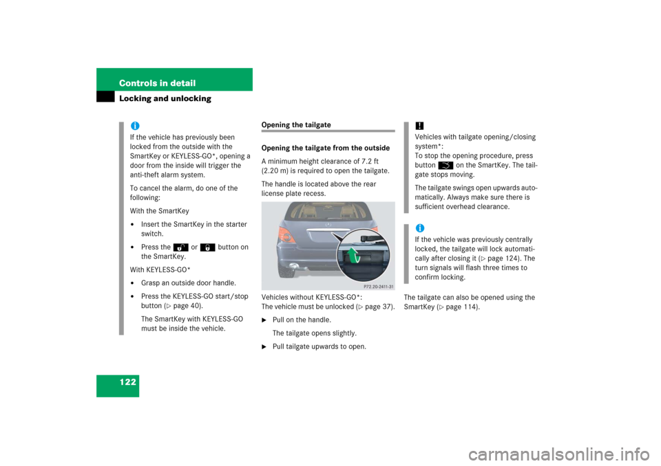
The handle is located above the rear
license plate recess.
Vehicles without KEYLESS-GO*:
The vehicle must be unlocked (
�page 37).
�
Pull on the handle.
The tailgate opens slightly.
�
Pull tailgate upwards to open.The tailgate can also be opened using the
SmartKey (
�page 114).
iIf the vehicle has previously been
locked from the outside with the
SmartKey or KEYLESS-GO*, opening a
door from the inside will trigger the
anti-theft alarm system.
To cancel the alarm, do one of the
following:
With the SmartKey�
Insert the SmartKey in the starter
switch.
�
Press theŒ or ‹button on
the SmartKey.
With KEYLESS-GO*
�
Grasp an outside door handle.
�
Press the KEYLESS-GO start/stop
button (
�page 40).
The SmartKey with KEYLESS-GO
must be inside the vehicle.
!Vehicles with tailgate opening/closing
system*:
To stop the opening procedure, press
buttonŠ on the SmartKey. The tail-
gate stops moving.
The tailgate swings open upwards auto-
matically. Always make sure there is
sufficient overhead clearance.iIf the vehicle was previously centrally
locked, the tailgate will lock automati-
cally after closing it (
�page 124). The
turn signals will flash three times to
confirm locking.
Page 124 of 561
123 Controls in detail
Locking and unlocking
Opening the tailgate from the inside
manually
You can unlock the tailgate from the
third-row seats and then open it manually.
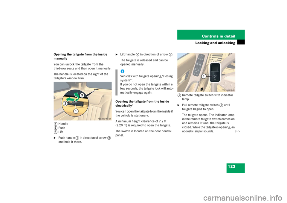
The handle is located on the right of the
tailgate’s window trim.
1Handle
2Push
3Lift�
Push handle 1 in direction of arrow2
and hold it there.
�
Lift handle 1 in direction of arrow3.
The tailgate is released and can be
opened manually.
Opening the tailgate from the inside
electrically*
You can open the tailgate from the inside if
the vehicle is stationary.
A minimum height clearance of 7.2 ft
(2.20 m) is required to open the tailgate.
The switch is located on the door control
panel.1Remote tailgate switch with indicator
lamp
�
Pull remote tailgate switch1 until
tailgate begins to open.
The tailgate opens. The indicator lamp
in the remote tailgate switch comes on
and remains lit until the tailgate is
closed. While the tailgate is opening, an
acoustic signal sounds.
iVehicles with tailgate opening/closing
system*:
If you do not open the tailgate within a
few seconds, the tailgate lock will auto-
matically engage again.
��
Page 125 of 561
124 Controls in detailLocking and unlocking
Limiting opening height of tailgate*
Vehicles with tailgate opening/closing
system*:
The tailgate opening height can be limited
when transporting goods on a roof rack*
(e.g. presence of an MB sport luggage con-
tainer*). When activated, the tailgate
opens to approximately 6.4 ft (1.95 m).�
Activate the limiting opening height of
tailgate using the control system
(�page 189).
Closing the tailgate
Closing the tailgate from the inside
electrically*
In vehicles with tailgate opening/closing
system* you can close the tailgate from
the inside using the remote tailgate switch.�
Press remote tailgate switch1
(�page 123) until tailgate begins to
close.
The tailgate closes. The indicator lamp
in the remote tailgate switch goes out.
While the tailgate is closing an acoustic
signal sounds.
To interrupt the closing procedure:
�
Press or pull remote tailgate switch1
(�page 123).
Warning!
G
Maintain sight of the area around the rear of
the vehicle while operating the tailgate with
the door-mounted remote tailgate switch or
with the Šbutton on the SmartKey or
SmartKey with KEYLESS-GO*. Monitor the
opening procedure carefully to make sure
no one is in danger of being injured.
To interrupt the opening procedure, press or
pull the door-mounted remote tailgate
switch or press the Šbutton on the
SmartKey or SmartKey with KEYLESS-GO*.!The tailgate swings open upwards auto-
matically. Always make sure there is
sufficient overhead clearance. To stop
the opening procedure, press or pull
remote tailgate switch1. The tailgate
stops moving.
iThe tailgate can also be opened using
theŠ button on the SmartKey or
SmartKey with KEYLESS-GO*
(�page 114).
��
Page 137 of 561
136 Controls in detailSeatsLumbar support
The curvature of the driver’s seat can be
adjusted to help enhance lower back sup-
port and seating comfort.
The lever for lumbar support adjustment is
located on the right hand side of the
driver’s seat backrest.
1Adjustment lever�
Move adjustment lever 1 in direction
of arrows until you have reached a
comfortable seating position.
Multicontour seat*
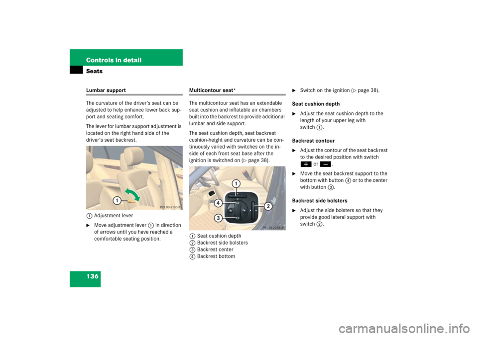
The multicontour seat has an extendable
seat cushion and inflatable air chambers
built into the backrest to provide additional
lumbar and side support.
The seat cushion depth, seat backrest
cushion-height and curvature can be con-
tinuously varied with switches on the in-
side of each front seat base after the
ignition is switched on (
�page 38).
1Seat cushion depth
2Backrest side bolsters
3Backrest center
4Backrest bottom
�
Switch on the ignition (
�page 38).
Seat cushion depth
�
Adjust the seat cushion depth to the
length of your upper leg with
switch1.
Backrest contour
�
Adjust the contour of the seat backrest
to the desired position with switch
æ orç.
�
Move the seat backrest support to the
bottom with button4 or to the center
with button3.
Backrest side bolsters
�
Adjust the side bolsters so that they
provide good lateral support with
switch2.
Page 140 of 561
139 Controls in detailSeats
�
To move seat backrest back, lean
lightly against backrest.
�
To move seat backrest forward, lean
forward with handle 1 pulled.
The seat backrest will move forward
against your back.
�
Release handle 1 when the seat back-
rest has reached the desired position.
To make sure the seat backrest has en-
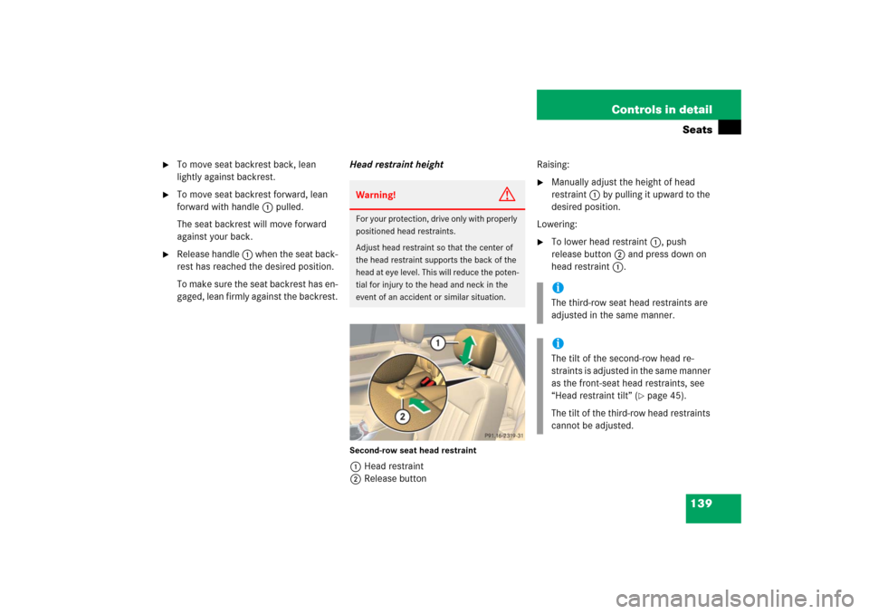
gaged, lean firmly against the backrest.Head restraint height
Second-row seat head restraint1Head restraint
2Release buttonRaising:
�
Manually adjust the height of head
restraint 1 by pulling it upward to the
desired position.
Lowering:
�
To lower head restraint 1, push
release button2 and press down on
head restraint 1.
Warning!
G
For your protection, drive only with properly
positioned head restraints.
Adjust head restraint so that the center of
the head restraint supports the back of the
head at eye level. This will reduce the poten-
tial for injury to the head and neck in the
event of an accident or similar situation.
iThe third-row seat head restraints are
adjusted in the same manner.iThe tilt of the second-row head re-
straints is adjusted in the same manner
as the front-seat head restraints, see
“Head restraint tilt” (
�page 45).
The tilt of the third-row head restraints
cannot be adjusted.
Page 145 of 561
144 Controls in detailMemory function*Prior to operating the vehicle, the driver
should check and adjust the seat height,
seat position fore and aft, and seat back-
rest angle if necessary, to ensure adequate
control, reach and comfort. The head re-
straint should also be adjusted for proper
height. See also the section on air bags
(�page 71) for proper seat positioning.
In addition, adjust the steering wheel to
ensure adequate control, reach, operation
and comfort. Both the interior and exterior
rear view mirrors should be adjusted for
adequate rear vision.
Fasten seat belts. Infants and small chil-
dren should be seated in a properly se-
cured restraint system that complies with
U.S. Federal Motor Vehicle Safety Stan-
dard 213 and 225 and Canadian Motor Ve-
hicle Safety Standards 213 and 210.2.With the memory function you can store up
to three different settings for each front
seat.
The following settings are saved for each
stored position on the entry side of the
driver’s seat:
�
Driver’s seat, head restraint height and
backrest position
�
Steering wheel position
�
Driver’s side exterior rear view mirror
position
�
Passenger-side exterior rear view
mirror position
The following are saved for each stored po-
sition on the entry side of the front passen-
ger seat:
�
Front passenger seat, head restraint
height and backrest position
Warning!
G
Do not activate the memory function while
driving. Activating the memory function
while driving could cause the driver to lose
control of the vehicle.
Page 178 of 561
177 Controls in detail
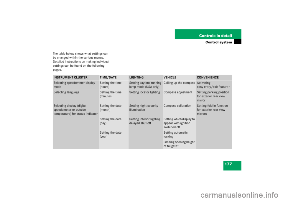
Control system
The table below shows what settings can
be changed within the various menus.
Detailed instructions on making individual
settings can be found on the following
pages.INSTRUMENT CLUSTER
TIME/DATE
LIGHTING
VEHICLE
CONVENIENCE
Selecting speedometer display
mode
Setting the time
(hours)
Setting daytime running
lamp mode (USA only)
Calling up the compass
Activating
easy-entry/exit feature*
Selecting language
Setting the time
(minutes)
Setting locator lighting
Compass adjustment
Setting parking position
for exterior rear view
mirror
Selecting display (digital
speedometer or outside
temperature) for status indicator
Setting the date
(month)
Setting night security
illumination
Compass calibration
Setting fold-in function
for exterior rear view
mirrors
Setting the date
(day)
Setting interior lighting
delayed shut-off
Setting which display to
appear with ignition
switched off
Setting the date
(year)
Setting automatic
lockingLimiting opening height
of tailgate*
Page 187 of 561
186 Controls in detailControl systemVehicle submenu
Access the
Vehicle
submenu via the
Settings
menu. Use the
Vehicle
submenu
to make general vehicle settings.
The following functions are available:Compass adjustment
This function is not available if your vehicle
is equipped with the Modular COMAND
system with navigation module*.
Determine your location on the basis of the
following zone maps.
Zone map North AmericaZone map South America
�
Press buttonæ orç to move
the selection marker to the
Vehicle
submenu.
Function
Page
Compass adjustment
186
Compass calibration
187
Setting which display to appear
with ignition switched off
188
Setting automatic locking
188
Limiting opening height of
tailgate*
189