Page 121 of 417
.
1Reset button
The instrument cl")
120 Controls in detail
Instrument cluster
A full view illustration of the instrument
cluster can be found in the “At a glance”
section of this manual (
�page 24).
1Reset button
The instrument cluster is activated when
you:
�Open a door.
�Switch on ignition.
�Press reset button1.
�Switch on the exterior lamps.
You can change the instrument cluster set-
tings in the Instrument cluster submenu of
the control system (
�page 136).
Instrument cluster illumination
Use the reset button to adjust the illumina-
tion brightness for the instrument cluster.
To brighten illumination
�Turn reset button1 in the instrument
cluster clockwise.
The instrument cluster illumination will
brighten.To dim illumination
�Turn reset button1 in the instrument
cluster counterclockwise.
The instrument cluster illumination will
dim.
Coolant temperature display
i
The instrument cluster illumination is
dimmed or brightened automatically to
suit ambient light conditions.
The instrument cluster illumination will
also be adjusted automatically when
you switch on the vehicle’s exterior
lamps.
Warning!G
�Driving when your engine is badly over-
heated can cause some fluids which
may have leaked into the engine com-
partment to catch fire. You could be se-
riously burned.
�Steam from an overheated engine can
cause serious burns and can occur just
by opening the hood. Stay away from
the engine if you see or hear steam com-
ing from it.
Turn off the engine, get out of the vehicle
and do not stand near the vehicle until the
engine has cooled down.
Page 128 of 417
127 Controls in detail
Control system
Menus, submenus and functions
Menu1Menu2Menu3Menu4Menu5Menu6Menu7
Standard
displayAUDIONAVIVehicle status
message
memorySettingsTrip computerTEL
(�page 128)(�page 128)(�page 130)(�page 131)(�page 132)(�page 145)(�page 146)
Commands/submenu
Coolant
temperature
displaySelect radio
stationShow route guid-
ance instruc-
tions, current
direction trav-
eledCall up vehicle
malfunction,
warning and
system status
messages stored
in memoryReset to factory
settingsFuel
consumption
statistics after
startLoad phone book
Digital
speedometerSelect satellite
radio station*
(USA only)Instrument
cluster submenuFuel
consumption
statistics since
the last resetSearch for name
in phone book
Call up mainte-
nance service
indicatorOperate CD
playerLighting
submenuCall up range
Check engine oil
levelVehicle submenu
Convenience
submenu
Page 132 of 417

131 Controls in detail
Control system
Vehicle status message memory menu
Use the vehicle status message memory
menu to scan malfunction and warning
messages that may be stored in the sys-
tem. Such messages appear in the multi-
function display and are based on
conditions or system status the vehicle’s
system has recorded.�Press buttonè orÿ repeatedly
until the vehicle status message mem-
ory appears in the multifunction dis-
play.
No vehicle status messages
If no conditions are recorded in memory,
the message in the multifunction display
is:
NO MALFUNCTION
Vehicle status messages have been
recorded
If conditions have occurred causing status
messages to be recorded, the number of
messages appears in the multifunction dis-
play:
1Number of messages
�Press buttonk orj.
The stored messages will now be dis-
played in order. See the “Practical
hints” section for malfunction and
warning messages (
�page 298).
Should the vehicle’s system record any
conditions while driving, the number of
messages will reappear in the multifunc-
tion display when the SmartKey in the
starter switch is turned to position0 or re-
moved from the starter switch.
Warning!G
Malfunction and warning messages are only
indicated for certain systems and are inten-
tionally not very detailed. The malfunction
and warning messages are simply a remind-
er with respect to the operation of certain
systems and do not replace the owner’s
and/or driver’s responsibility to maintain
the vehicle’s operating safety by having all
required maintenance and safety checks
performed on the vehicle and by bringing
the vehicle to an authorized Mercedes-Benz
Light Truck Center to address the malfunc-
tion and warning messages (
�page 298).
i
The vehicle status message memory
will be cleared when you switch on igni-
tion (
�page 35). You will then only see
high-priority messages in the multi-
function display (
�page 298).
Page 154 of 417

153 Controls in detail
Automatic transmission
Driving tips
Accelerator position
Your driving style influences the
transmission’s shifting behavior:
Less throttle Earlier upshifting
More throttle Later upshifting
Kickdown
Use kickdown when you want maximum
acceleration.
�Press the accelerator past the point of
resistance.
The transmission shifts into a lower
gear.
�Ease on the accelerator when you have
reached the desired speed.
The transmission shifts up again.Stopping
When you stop briefly, e.g. at traffic lights:
�Leave the transmission in gear.
�Hold the vehicle with the brake.
When you stop longer with the engine
idling and/or on a hill:
�Set the parking brake.
�Move the gear selector lever to
positionP.Maneuvering
When you maneuver in tight areas,
e.g. when pulling into a parking space:
�Control the vehicle speed by gradually
releasing the brakes.
�Accelerate gently.
�Never abruptly step on the accelerator.
Working on the vehicle
Warning!G
When working on the vehicle, set the
parking brake and move gear selector lever
to positionP. Otherwise the vehicle could
roll away.
Page 159 of 417
 of the trans-
fer case switch.
Once the shift is complete, gear
position
H is displayed in the transfer")
158 Controls in detail
Transfer case
Switching from LOW to HIGH
�Press lower half (“HIGH”) of the trans-
fer case switch.
Once the shift is complete, gear
position
H is displayed in the transfer
case indicator.
� Put gear selector in D.Messages in the multifunction display
If a shift was not completed and the multi-
function display shows one of the following
messages:
�TC SHIFT CONDITIONS NOT FULFILLED
The shift did not take place. At least
one shift condition was not met.
�Repeat the shift procedure.
�TC IN NEUTRAL
The shift did not take place. The trans-
fer case is in neutral. The gear
position
N is displayed in transfer case
indicator1.
�Repeat the shift procedure.
�TC SHIFT – CANCELLED
The shift did not take place.
�Repeat the shift procedure.
�TRANSFER CASE – VISIT WORKSHOP!
There may be a malfunction in the
system.
�Repeat the shift procedure.
�If the shift procedure still does not take
place, have the vehicle checked at an
authorized Mercedes-Benz Light Truck
Center as soon as possible.
For more information, see “Practical hints”
section (
�page 321).
!
The shift procedure can only be per-
formed when:
�The engine is running.
�The gear selector lever for the auto-
matic transmission is in positionN.
�The vehicle is not at standstill.
�The vehicle speed does not exceed
40 mph (70 km/h).
i
If the shift procedure does not take
place press lower half (“HIGH”) of the
transfer case switch again.
Warning!G
If TC is in neutral, transmission positionP
will not hold vehicle. The parking brake must
be applied to hold vehicle in place.
i
If the SmartKey is in starter switch
position0 or1, an alarm will sound if
the transfer case is in positionN and
the driver’s door is opened.
Engage transfer case to gear position
HIGH or LOW.
Page 164 of 417
 and for
setting the exterior rear view mirrors, see
“Mirrors�")
163 Controls in detail
Good visibility
�Good visibility
For information on windshield wipers, see
“Windshield wipers” (
�page 53) and for
setting the exterior rear view mirrors, see
“Mirrors” (
�page 41).
Rear view mirrors
Auto-dimming mirrors
The reflection brightness of the exterior
rear view mirrors and the interior rear view
mirror will respond automatically to glare
when
�ignition is switched on, and
�incoming light from headlamps falls on
the sensor in the interior rear view
mirror
The interior rear view mirror will not react if
�reverse gear is engaged
�the interior lighting is turned on
Warning!G
The auto-dimming function does not react if
incoming light is not aimed directly at sen-
sors in the interior rear view mirror.
The interior rear view mirror and the exterior
rear view mirrors do not react, for example,
when transporting cargo which covers the
rear window.
Glare can endanger you and others.
Warning!G
In case of an accident, liquid electrolyte may
escape from the mirror housing if the mirror
glass breaks.
Electrolyte has an irritating effect. Do not al-
low the liquid to come into contact with
eyes, skin, clothing, or the respiratory sys-
tem. In case it does, immediately flush af-
fected area with water, and seek medical
help if necessary.
!
Electrolyte drops coming into contact
with the vehicle paint finish can be
completely removed only while in the
liquid state by applying plenty of water.
Page 187 of 417

186 Controls in detail
Driving systems
Warning indicator
Visual signals indicate to the driver the rel-
ative distance between the sensors and an
obstacle. The warning indicator is located
next to the tailgate.
Warning indicator
As your vehicle approaches an object, one
or more segments will come on, depending
on the distance. When the sixth segment
lights, you have reached the minimum dis-
tance.An intermittent acoustic warning will
sound when the first yellow segment
comes on. This signal quickens with each
additional segment lit. When all segments
illuminate, the acoustic warning becomes
a constant signal. The signal is canceled
when the gear selector lever is placed in
position D or P.
Rear Parking Assist malfunction
There is a malfunction in the Rear Parking
Assist system if:
�a low warning tone sounds while the
vehicle is reversing
The Rear Parking Assist sensors are
dirty or malfunctioning.
�Clean the Rear Parking Assist sys-
tem sensors (
�page 286).
�Switch on the ignition again.
�no segments come on and no warning
sounds
The Rear Parking Assist is malfunction-
ing.
�Have the Rear Parking Assist sys-
tem checked by an authorized
Mercedes-Benz Light Truck Center
as soon as possible.
Malfunction may also be caused by inter-
ference from other radio or ultrasonic sig-
nals.
�Check the Rear Parking Assist opera-
tion at another location to rule out in-
terference from outside radio or
ultrasonic signals.
Page 198 of 417
197 Controls in detail
Useful features
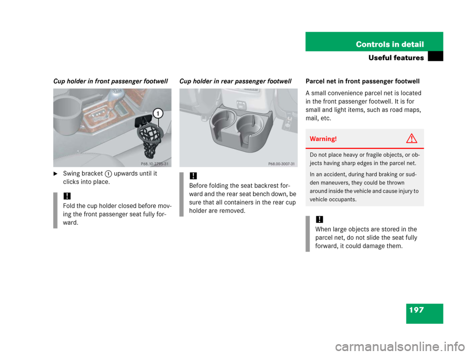
Cup holder in front passenger footwell
�Swing bracket1 upwards until it
clicks into place.Cup holder in rear passenger footwellParcel net in front passenger footwell
A small convenience parcel net is located
in the front passenger footwell. It is for
small and light items, such as road maps,
mail, etc.
!
Fold the cup holder closed before mov-
ing the front passenger seat fully for-
ward.
!
Before folding the seat backrest for-
ward and the rear seat bench down, be
sure that all containers in the rear cup
holder are removed.
Warning!G
Do not place heavy or fragile objects, or ob-
jects having sharp edges in the parcel net.
In an accident, during hard braking or sud-
den maneuvers, they could be thrown
around inside the vehicle and cause injury to
vehicle occupants.
!
When large objects are stored in the
parcel net, do not slide the seat fully
forward, it could damage them.