Page 335 of 521

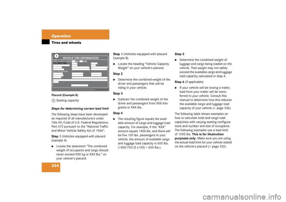
334 OperationTires and wheelsPlacard (Example B)1Seating capacity
Steps for determining correct load limit
The following steps have been developed
as required of all manufacturers under
Title 49, Code of U.S. Federal Regulations,
Part 575 pursuant to the “National Traffic
and Motor Vehicle Safety Act of 1966”.
Step 1 (Vehicles equipped with placard
Example A)�
Locate the statement “The combined
weight of occupants and cargo should
never exceed XXX kg or XXX lbs.” on
your vehicle’s placard.Step 1 (Vehicles equipped with placard
Example B)
�
Locate the heading “Vehicle Capacity
Weight” on your vehicle’s placard.
Step 2
�
Determine the combined weight of the
driver and passengers that will be
riding in your vehicle.
Step 3
�
Subtract the combined weight of the
driver and passengers from XXX kilo-
grams or XXX lbs.
Step 4
�
The resulting figure equals the avail-
able amount of cargo and luggage load
capacity. For example, if the “XXX”
amount equals 1400 lbs. and there will
be five 150 lbs. passengers in your
vehicle, the amount of available cargo
and luggage load capacity is 650 lbs.
(1400-750 (5 x150) = 650 lbs.).Step 5
�
Determine the combined weight of
luggage and cargo being loaded on the
vehicle. That weight may not safely
exceed the available cargo and luggage
load capacity calculated in step 4.
Step 6 (if applicable)
�
If your vehicle will be towing a trailer,
load from your trailer will be trans-
ferred to your vehicle. Consult this
manual to determine how this reduces
the available cargo and luggage load
capacity of your vehicle (
�page 336).
The following table shows examples on
how to calculate total and cargo load
capacities with varying seating configura-
tions and number and size of occupants.
The following examples use a load limit
of 1500 lbs. This is for illustration
purposes only. Make sure you are using
the actual load limit for your vehicle stated
on the vehicle’s placard (
�page 332).
Page 425 of 521

424 Practical hintsWhere will I find ...?Vehicle tool kit
The vehicle tool kit is stored in the com-
partment underneath the trunk floor
(�page 422).
The vehicle tool kit includes:
�
One pair of universal pliers
�
One towing eye bolt
�
One wheel wrench
�
One alignment bolt
�
One fuse extractor
�
Spare fuses
�
Collapsible wheel chock
�
A pair of gloves
Setting up the collapsible wheel chock
The collapsible wheel chock serves to
additionally secure the vehicle, e.g. while
changing the wheel.1Tilt the plates upward
2Fold the lower plate outward
3Insert the plate
�
Tilt both plates upward1.
�
Fold the lower plate outward2.
�
Guide the tabs of the lower plate all the
way into the openings of the base
plate3.
Vehicle jackWarning!
G
The jack is designed exclusively for jacking
up the vehicle at the jack take-up brackets
built into both sides of the vehicle. To help
avoid personal injury, use the jack only to lift
the vehicle during a wheel change. Never
get beneath the vehicle while it is supported
by the jack. Keep hands and feet away from
the area under the lifted vehicle. Always
firmly set parking brake and block wheels
before raising vehicle with jack.
Do not disengage parking brake while the
vehicle is raised. Be certain that the jack is
always vertical (plumb line) when in use,
especially on hills. Always try to use the jack
on level surface. Make sure the jack arm is
fully seated in the jack take-up bracket.
Always lower the vehicle onto sufficient
capacity jackstands before working under
the vehicle.
Page 518 of 521

517 Index
Trunk
Cargo area
Closing the lid 121
Fuse box 462
Lamp 149
Lock button, KEYLESS-GO* 117
Message in display 419
Opening 110, 120
Tie-down rings 275
Trunk lid emergency release 127
Unlocking in an emergency 427
Valet locking 128
Turn signal lamps
Cleaning lenses 367
Messages in display 415
Replacing bulbs 437
Turn signals 55
Additional in mirrors 434
Bulbs 434
Cleaning lenses 367
Indicator lamps 25
Turning off engine 62U
Uniform Tire Quality Grading
Standards 356
Units, Settings
Speedometer 166
Temperature 166
Unleaded gasoline, Premium 488
Uphill driving
Cruise control 244
Upholstery
Cleaning 371
Useful features 276
V
Vacuum line routing diagram label 468
Valet locking 128
Vehicle
Battery 450
Care 364
Control system, settings menu 153
Dimensions 482
Individual settings 163, 165
Locking/unlocking 34, 60, 106
Locking/unlocking in an
emergency 426, 427
Lowering 447Modifications and alterations, Operat-
ing safety 16
Towing 457
Washing 364
Weights 483
Vehicle capacity weight 356
Vehicle Identification Number see VIN
Vehicle jack 422, 424
Vehicle level control see Airmatic DC (Dual
Control)*
Vehicle lighting 318
Vehicle loading
Cargo tie-down rings 275
Instructions 274
Load limit 334
Roof rack* 268
Ski sack* 268
Split rear bench seat* 271
Terminology 353
Vehicle maximum load on the tire 356
Vehicle Recovery services, Stolen (Tele
Aid) 293
Vehicle status message memory 162
Vehicle tool kit 424
Vehicle washing 366
VIN 499