Page 160 of 262
HAZARD FLASHER
The hazard flasher is located on the
steering column, just behind the
steering wheel. The hazard flashers
will operate when the ignition is in
any position or if the key is not in
the ignition.
Push in the flasher control and all
front and rear direction signals will
flash. Press the flasher control again
to turn them off. Use it when your
vehicle is disabled and is creating a
safety hazard for other motorists.
Note:With extended use, the flasher may run down your battery.
FUEL PUMP SHUT-OFF SWITCH
This device stops the electric fuel pump from sending fuel to the engine
when your vehicle has had a substantial jolt.
After an accident, if the engine cranks but does not start, this switch
may have been activated.
2006 B-Series(mbs)
Owners Guide (post-2002-fmt)
Canadian_French(fr_can)
Roadside Emergencies
160
Page 164 of 262

Fuse/Relay
LocationFuse Amp
RatingPassenger Compartment Fuse
Panel Description
11 10A Smart Junction Box (SJB) (Logic
power)
12 — Not used
13 15A Horn, Interior lamps
14 15A High beam headlamp, High beam
indicator (cluster)
15 — One-touch down relay
16 30A cartridge
fusePower windows
17 15A Turn signals/Hazards
18 — Not used
19 20A Center High-Mounted Stop Lamp
(CHMSL)/Stop lamps
20 10A Anti-lock Brake System (ABS)
module, Brake-shift interlock,
Speed control module, Back-up
lamps, Overdrive cancel switch,
Electronic flasher (turn/hazard)
21 5A Starter relay coil
22 5A Radio (START), 4x4 Neutral
sense (manual only)
23 30A Headlamps (low and high beam)
24 20A Radio battery feed (B+)
25 — Accessory relay
26 2A Brake pressure switch
27 10A Climate control blower relay/blend
doors, 4x4 module
28 15A 4x4 module battery feed (B+)
29 20A Cigar lighter, Diagnostic connector
(OBD II)
30 5A Power mirrors
2006 B-Series(mbs)
Owners Guide (post-2002-fmt)
Canadian_French(fr_can)
Roadside Emergencies
164
Page 165 of 262
Fuse/Relay
LocationFuse Amp
RatingPassenger Compartment Fuse
Panel Description
31 20A Front park lamps, Rear park
lamps, License plate lamps,
Dimmer switch, Trailer tow park
lamps
32 5A Brake switch (logic)
33 5A Instrument cluster battery feed
(B+)
34 20A Power point
35 15A Power locks
Power distribution box
The power distribution box is
located in the engine compartment.
The power distribution box contains
high-current fuses that protect your
vehicle’s main electrical systems
from overloads.
WARNING: Always disconnect the battery before servicing
fuses.
WARNING: To reduce risk of electrical shock, always replace
the cover to the Power Distribution Box before reconnecting
the battery or refilling fluid reservoirs.
If the battery has been disconnected and reconnected, refer to the
Batterysection of theMaintenance and specificationschapter.
2006 B-Series(mbs)
Owners Guide (post-2002-fmt)
Canadian_French(fr_can)
Roadside Emergencies
165
Page 181 of 262

If you find a leak or other damage, or if coolant is still leaking, stop the
engine and call an authorized dealer.
SeeAdding coolantin theMaintenance and Specificationssection. If
you find no problems, the engine is cool and no leaks are obvious,
carefully add coolant as required.
WARNING: When the engine and radiator are hot, scalding
coolant and steam may shoot out under pressure and cause
serious injury. Do not remove the cooling system cap when the
engine and radiator are hot.
Note:If the engine continues to overheat or frequently overheats, have
the cooling system inspected. The engine could be seriously damaged
unless repairs are made.
JUMP STARTING
WARNING: The gases around the battery can explode if
exposed to flames, sparks, or lit cigarettes. An explosion could
result in injury or vehicle damage.
WARNING: Batteries contain sulfuric acid which can burn skin,
eyes and clothing, if contacted.
Do not attempt to push-start your vehicle. Automatic
transmissions do not have push-start capability; doing so may
damage the catalytic converter.
Preparing your vehicle
When the battery is disconnected or a new battery is installed, the
transmission must relearn its shift strategy. As a result, the transmission
may have firm and/or soft shifts. This operation is considered normal and
will not affect function or durability of the transmission. Over time, the
adaptive learning process will fully update transmission operation.
1.Use only a 12–volt supply to start your vehicle.
2. Do not disconnect the battery of the disabled vehicle as this could
damage the vehicle’s electrical system.
3. Park the booster vehicle close to the hood of the disabled vehicle
making sure the two vehiclesdo nottouch. Set the parking brake on
both vehicles and stay clear of the engine cooling fan and other
moving parts.
2006 B-Series(mbs)
Owners Guide (post-2002-fmt)
Canadian_French(fr_can)
Roadside Emergencies
181
Page 182 of 262
4. Check all battery terminals and remove any excessive corrosion
before you attach the battery cables. Ensure that vent caps are tight
and level.
5. Turn the heater fan on in both vehicles to protect any electrical
surges. Turn all other accessories off.
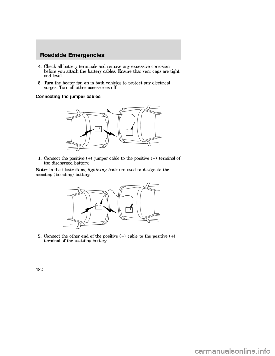
Connecting the jumper cables
1. Connect the positive (+) jumper cable to the positive (+) terminal of
the discharged battery.
Note:In the illustrations,lightning boltsare used to designate the
assisting (boosting) battery.
2. Connect the other end of the positive (+) cable to the positive (+)
terminal of the assisting battery.
+–+–
+–+–
2006 B-Series(mbs)
Owners Guide (post-2002-fmt)
Canadian_French(fr_can)
Roadside Emergencies
182
Page 183 of 262
3. Connect the negative (-) cable to the negative (-) terminal of the
assisting battery.
4. Make the final connection of the negative (-) cable to an exposed
metal part of the stalled vehicle’s engine, away from the battery and
the fuel injection system.Do notuse fuel lines, engine rocker covers
or the intake manifold asgroundingpoints.
WARNING: Do not connect the end of the second cable to the
negative (-) terminal of the battery to be jumped. A spark may
cause an explosion of the gases that surround the battery.
5. Ensure that the cables are clear of fan blades, belts, moving parts of
both engines, or any fuel delivery system parts.
Jump starting
1. Start the engine of the booster vehicle and run the engine at
moderately increased speed.
2. Start the engine of the disabled vehicle.
+–+–
+–+–
2006 B-Series(mbs)
Owners Guide (post-2002-fmt)
Canadian_French(fr_can)
Roadside Emergencies
183
Page 184 of 262
3. Once the disabled vehicle has been started, run both engines for an
additional three minutes before disconnecting the jumper cables.
Removing the jumper cables
Remove the jumper cables in the reverse order that they were
connected.
1. Remove the jumper cable from thegroundmetal surface.
Note:In the illustrations,lightning boltsare used to designate the
assisting (boosting) battery.
2. Remove the jumper cable on the negative (-) connection of the
booster vehicle’s battery.
+–+–
+–+–
2006 B-Series(mbs)
Owners Guide (post-2002-fmt)
Canadian_French(fr_can)
Roadside Emergencies
184
Page 185 of 262
3. Remove the jumper cable from the positive (+) terminal of the
booster vehicle’s battery.
4. Remove the jumper cable from the positive (+) terminal of the
disabled vehicle’s battery.
After the disabled vehicle has been started and the jumper cables
removed, allow it to idle for several minutes so the engine computer can
relearnits idle conditions.
+–+–
+–+–
2006 B-Series(mbs)
Owners Guide (post-2002-fmt)
Canadian_French(fr_can)
Roadside Emergencies
185