2006 LAND ROVER FRELANDER 2 cooling
[x] Cancel search: coolingPage 1294 of 3229
W hen movi ng from a st andst il l, ups hi ft s can be pre-s el ect ed by making '+' s el ect ions wi th the s elect or l ever for thenumber of ups hifts requi red. The TCM t hen performs t he reques ted number of upshi ft s when appropri at e s hift points arereached. For exampl e; when moving off in 1s t gear, if 3 '+' s elect ions are made i n quick s ucces si on, t he TCM willautomat ically ups hift t hrough the gears to 4t h gear as t he vehi cl e accelerates , wit hout any furt her s electi ons bei ng made.
Cooling
Cooling mode is act ivated when t he TCM det ect s exces s ively hi gh trans mi s si on fl uid or engine coolant temperatures . W hent hi s mode i s act ive torque converter l ock-up is acti vat ed earl ier t o mi ni mi ze a further ris e in fl uid and/or engine coolantt emperature and ass i st flui d cool ing.
Hill Descent Control (HDC)
The HDC mode as s is t s t he ABS module i n cont rol li ng the downhil l speed of t he vehi cl e. W hen HDC i s acti ve, t he TCMs elect s t he mos t appropri at e gear for t he descent to maxi mi ze engi ne braking.
Maximum engi ne braking i s applied us i ng a s hift map which i nit iat es later ups hift s and earl y downshi ft s .
Cruise
W hen s peed cont rol i s act ivated, t he TCM receives a speed control acti ve mes s age on the hi gh s peed CAN bus . The TCMact ivat es a s peed cont rol map whi ch minimizes up and down s hifts .
Crui se mode is act ive when s peed cont rol is sel ect ed on and t he transmis s ion i s in drive 'D', s port 'S', HDC or Terrai nRespons e Gras s /gravel /s now program. Unique cruis e maps overri de the current mode t o provide a smoot h driving feel andmode resel ect ion.
Limp Home
If a transmis s ion faul t is det ect ed by t he TCM, the TCM adopt s a l imp home s trategy and a mes s age 'TRANSMISSIONFAULT LIMITED GEARS AVAILABLE' i s dis played in the mes s age cent er. If the fault has an effect on engi ne emis s ions , theMIL in the i nst rument clus t er wi ll als o be il luminat ed.
In li mp home mode, P, R and N functi ons operate normall y (i f the fault al lows t hes e s elect ions) and t he TCM locks t het ransmis s ion i n 3rd gear t o all ow t he dri ver t o t ake the vehicle to a Land Rover deal er or approved repai rer. Torqueconvert er lock-up i s dis abled and reverse-lock-out wil l not funct ion.
If the vehicle is s t opped and s ubsequentl y res tarted in t he li mp home mode condi ti on, t he TCM operat es normall y unti l thefaul t which caus ed t he condi ti on is det ect ed agai n.
Coast
Coast mode provides earli er downs hifts during coast ing dependant on out put shaft decelerat ion rate to improve driveabili tyand refinement by avoi ding negati ve to pos it ive driveli ne torque revers als t rans mi ssion during t he downshi ft s .
Fast Off Recognition
Fast off recogni ti on is act ivated when t he TCM det ect s t hat t he dri ver has releas ed the accel erat or pedal qui ckl y. This isdetected by the TCM monit oring for a high level of negat ive pedal angl e from ECM s ignals on t he high speed CAN bus . Ift hi s condi ti on is det ect ed, t he TCM hol ds the current gear rati o to allow the driver t o compl ete the manoeuvre wi thout t heneed for a downs hift. The mode can remain acti ve for a predet ermined lengt h of ti me or i f the driving s t yl e remainspass i ve.
Fast off recogni ti on mode as si s ts vehicle st abili ty and is us ed i n conjunct ion a lateral accel erat ion i nput duri ng corneri ng tomaint ain t he current gear unti l the corner is negot iated.
Uphill and Trailer
Uphill and t rai ler mode can be acti ve when the trans mi s si on is operat ing in normal, s port or Terrai n Res pons e modes .W hen t he vehicle i s pull ing a t rai ler or dri vi ng up an i ncl ine, the TCM det ects t he i ncreas ed res i st ance by monit oring enginet orque and s peed s i gnal s received from the ECM on the hi gh s peed CAN bus and als o t rans mis s ion out put s haft s peeds ens or s ignals . Uphi ll and t rai ler mode wi ll provide downs hift s t o prevent a drop in t rans mi ss i on torque out put andmaint ain driving force.
Downhill
Downhill mode can be act ive when t he t ransmis s ion i s operati ng in normal, s port or Terrain Res pons e modes . W hen t hevehi cl e i s descendi ng an i ncl ine t he TCM detect s a reducti on in res is t ance by moni toring engine t orque and s peed si gnal sreceived from the ECM on t he high s peed CAN bus and als o t rans mis s ion out put shaft speed s ensor s ignals . Downhill modeas si st s engine braki ng by s elect ing an appropriat e gear reduci ng the load required on t he brakes .
Wide Throttle
W i de open thrott le mode operates for part thrott le ups hifts and ki ck-down ups hifts . It provides cons i st ent wide opent hrott le ups hift performance under all driving condit ions. The full engine s peed range is used i n all driving modes ; normal ,s port, hi ll modes and Commands hi ft . Compens at ion i s used for delays (hydrauli c and electroni c) in gear change reques t togear change s tart to provi de s mooth changes and correct shi ft point correct ion.
Terrain Response
The Terrai n Res pons e s ys tem has a unique s et of shi ft maps for each of t he Terrai n Res pons e programs . Thes e programsoverri de exis ti ng modes; for exampl e when HDC is acti ve and the 'Sand', 'Mud and Ruts ' or 'Grass /Gravel/Snow' programsare sel ect ed, a specific Terrain Res ponse map is used, not the HDC mode s hift map detai led previ ous ly.
Page 1356 of 3229
Publi s hed: 11-May-2011
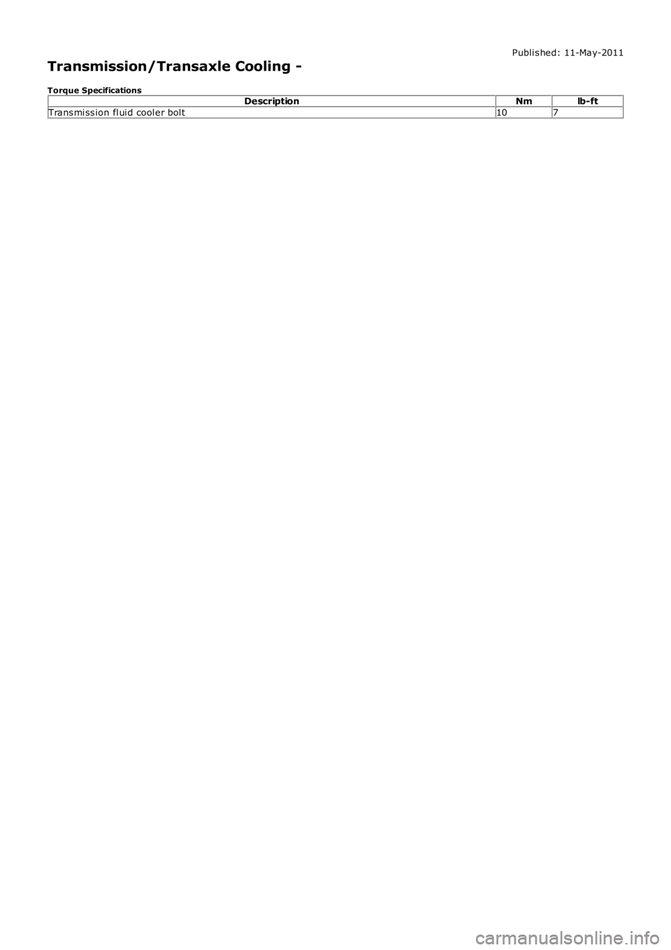
Transmission/Transaxle Cooling -
Torque SpecificationsDescriptionNmlb-ft
Trans mi ss ion fl ui d cool er bol t107
Page 1357 of 3229
Publi s hed: 11-May-2011
Transmission/Transaxle Cooling - Transmission Cooling
Des cript ion and Operat ion
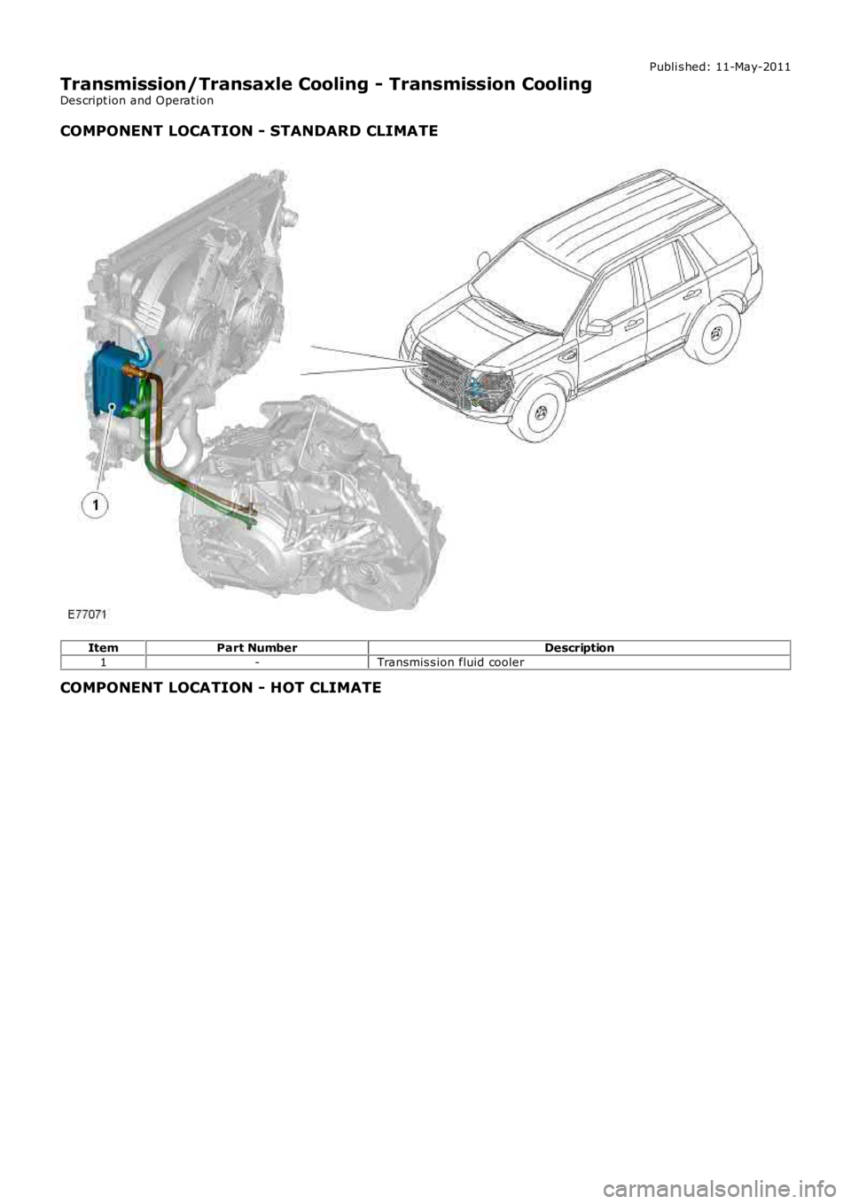
COMPONENT LOCATION - STANDARD CLIMATE
ItemPart NumberDescription
1-Transmis s ion fluid cooler
COMPONENT LOCATION - HOT CLIMATE
Page 1360 of 3229
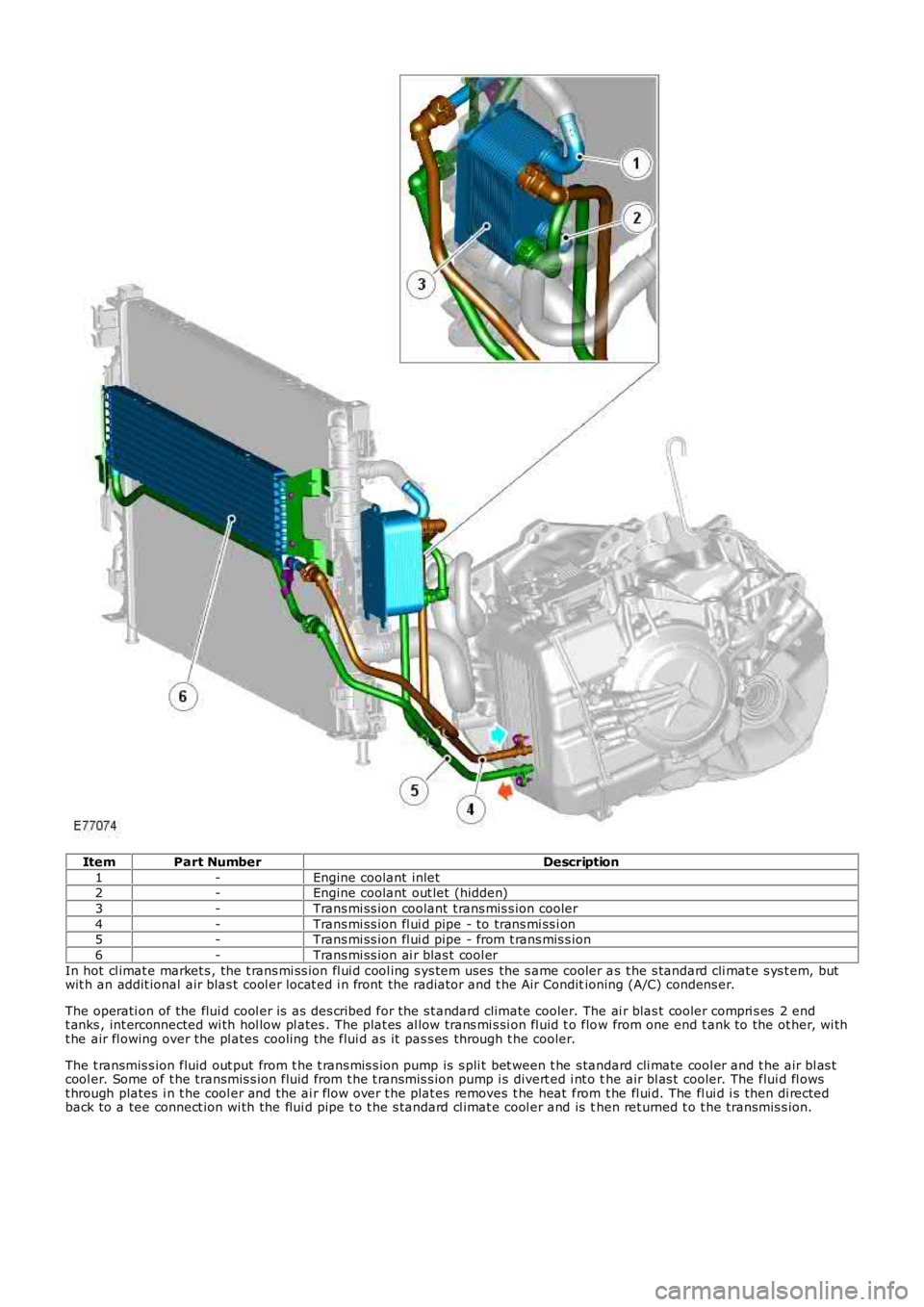
ItemPart NumberDescription
1-Engine coolant inlet2-Engine coolant out let (hidden)
3-Trans mi ss ion coolant t rans mis s ion cooler
4-Trans mi ss ion fl ui d pipe - to trans mi ss i on5-Trans mi ss ion fl ui d pipe - from t rans mis s ion
6-Trans mi ss ion ai r blas t cool er
In hot cl imat e market s , the t rans mi ss ion fl ui d cool ing s ys tem uses the s ame cooler as t he s tandard cli mat e s ys t em, butwit h an addit ional air blas t cool er locat ed i n front the radiator and t he Air Conditioning (A/C) condens er.
The operati on of the flui d cool er is as des cribed for the s t andard climate cooler. The ai r blas t cooler compri s es 2 endt anks , int erconnected wi th hol low pl ates . The plat es al low trans mi s si on fl uid t o flow from one end t ank to the ot her, wi tht he air fl owing over the pl ates cooling the flui d as it pas s es through t he cooler.
The t ransmis s ion fluid out put from t he t rans mis s ion pump is s pli t bet ween t he s tandard cli mate cool er and t he air bl as tcool er. Some of t he transmis s ion fluid from t he t ransmis s ion pump i s divert ed i nt o the air bl as t cooler. The flui d fl owst hrough plates i n t he cool er and the ai r flow over t he plat es removes t he heat from t he fl ui d. The fl ui d i s then di rectedback to a tee connect ion wi th the flui d pipe t o t he s tandard cl imat e cool er and is then ret urned t o t he transmis s ion.
Page 1361 of 3229
Publi s hed: 11-May-2011
Transmission/Transaxle Cooling - Transmission Cooling
Diagnosi s and Tes ti ng
Principles of Operation
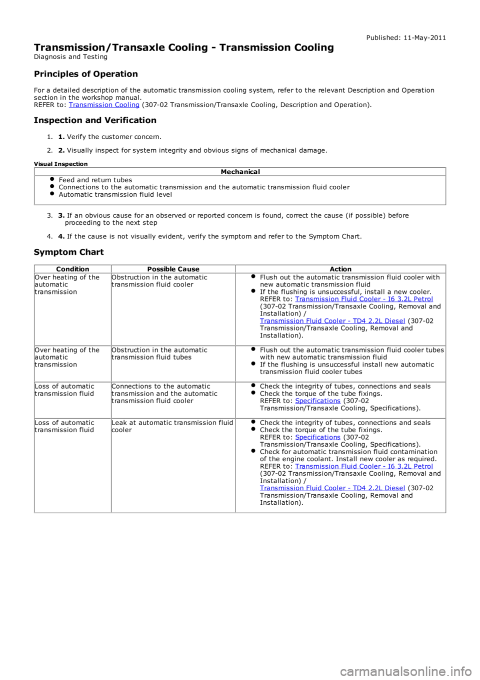
For a detail ed descripti on of the aut omati c transmis s ion cool ing s ys tem, refer t o t he relevant Descripti on and Operat ions ect ion i n t he works hop manual .REFER to: Trans mi ss i on Cool ing (307-02 Trans mi ss ion/Transaxle Cool ing, Descripti on and Operat ion).
Inspection and Verification
1. Verify t he cus t omer concern.1.
2. Vis ually ins pect for s ys tem int egrit y and obvi ous s igns of mechanical damage.2.
Visual Inspection
Mechanical
Feed and ret urn t ubesConnect ions t o the aut omati c t ransmis s ion and t he automat ic t rans mis s ion flui d cool erAutomat ic trans mi ss i on fl uid l evel
3. If an obvious cause for an obs erved or report ed concern is found, correct t he caus e (if pos s ible) beforeproceeding t o t he next s t ep3.
4. If t he caus e is not vis ually evi dent , verify t he sympt om and refer t o t he Sympt om Chart.4.
Symptom Chart
ConditionPossible CauseAction
Over heat ing of t heautomat ict rans mis s ion
Obs truct ion i n t he automat ict rans mis s ion fluid cool erFl us h out t he automat ic t rans mi ss ion fl ui d cool er wit hnew aut omati c t rans mis s ion fluidIf t he fl ushi ng is uns ucces sful, ins t al l a new cooler.REFER t o: Transmis s ion Flui d Cooler - I6 3.2L Petrol(307-02 Trans mi ss i on/Trans axl e Cooling, Removal andIns tall ati on) /Trans mi s si on Fluid Cool er - TD4 2.2L Di es el (307-02Trans mi s si on/Trans axl e Cooli ng, Removal andIns tall ati on).
Over heat ing of t heautomat ict rans mis s ion
Obs truct ion i n t he automat ict rans mis s ion fluid tubesFl us h out t he automat ic t rans mi ss ion fl ui d cool er tubeswit h new automat ic t rans mi ss i on fl ui dIf t he fl ushi ng is uns ucces sful ins tall new aut omati ct rans mi ss i on fl ui d cooler tubes
Loss of aut omati ct rans mis s ion flui dConnect ions to the aut omati ct rans mis s ion and t he automat ict rans mis s ion fluid cool er
Check t he int egrit y of tubes , connect ions and s ealsCheck t he torque of t he t ube fi xi ngs.REFER t o: Specificati ons (307-02Trans mi s si on/Trans axl e Cooli ng, Speci fi cat ions ).
Loss of aut omati ct rans mis s ion flui dLeak at aut omati c t ransmis s ion fluidcool erCheck t he int egrit y of tubes , connect ions and s ealsCheck t he torque of t he t ube fi xi ngs.REFER t o: Specificati ons (307-02Trans mi s si on/Trans axl e Cooli ng, Speci fi cat ions ).Check for aut omat ic trans mi s si on fl uid contami nat ionof t he engine cool ant. Inst all new cooler as required.REFER t o: Transmis s ion Flui d Cooler - I6 3.2L Petrol(307-02 Trans mi ss i on/Trans axl e Cooling, Removal andIns tall ati on) /Trans mi s si on Fluid Cool er - TD4 2.2L Di es el (307-02Trans mi s si on/Trans axl e Cooli ng, Removal andIns tall ati on).
Page 1362 of 3229
Publi s hed: 11-May-2011
Transmission/Transaxle Cooling - Transmission Fluid CoolerI6 3.2L Petrol
Removal and Inst all ati on
Removal
Remove t he cover and dis connect the bat tery ground cabl e.
Refer t o: Specificati ons (414-00 Bat tery and Charging Sys tem -General Informat ion, Specificati ons).
1.
2. W ARNING: Make sure t o s upport the vehicle wit h axles tands .
Rais e and s upport t he vehi cl e.
2.
Drai n t he t ransmis s ion fluid.
Refer t o: Transmis s ion Flui d Drai n and Refi ll - I6 3.2L Pet rol (307-01Automat ic Transmis si on/Trans axl e, General Procedures ).
3.
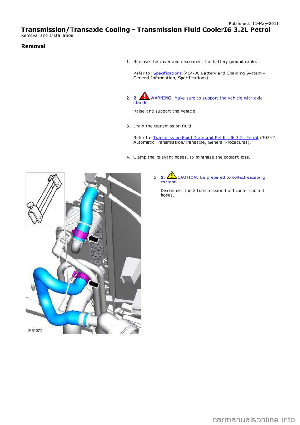
Clamp the relevant hos es , to mini mis e t he cool ant los s.4.
5. CAUTION: Be prepared to col lect escapingcool ant.
Di sconnect t he 2 t rans mis s ion flui d cool er coolanthos es .
5.
Page 1365 of 3229
Publi s hed: 11-May-2011
Transmission/Transaxle Cooling - Transmission Fluid CoolerTD4 2.2L Diesel
Removal and Inst all ati on
Removal
Remove t he cover and dis connect the bat tery ground cabl e.
Refer t o: Specificati ons (414-00 Bat tery and Charging Sys tem -
General Informat ion, Specificati ons).
1.
2. W ARNING: Make sure t o s upport the vehicle wit h axle
s tands .
Rais e and s upport t he vehi cl e.
2.
Drai n t he t ransmis s ion fluid.
Refer t o: Transmis s ion Flui d Drai n and Refi ll - TD4 2.2L Dies el (307-01 Automat ic Trans mi s si on/Trans axl e, General Procedures ).
3.
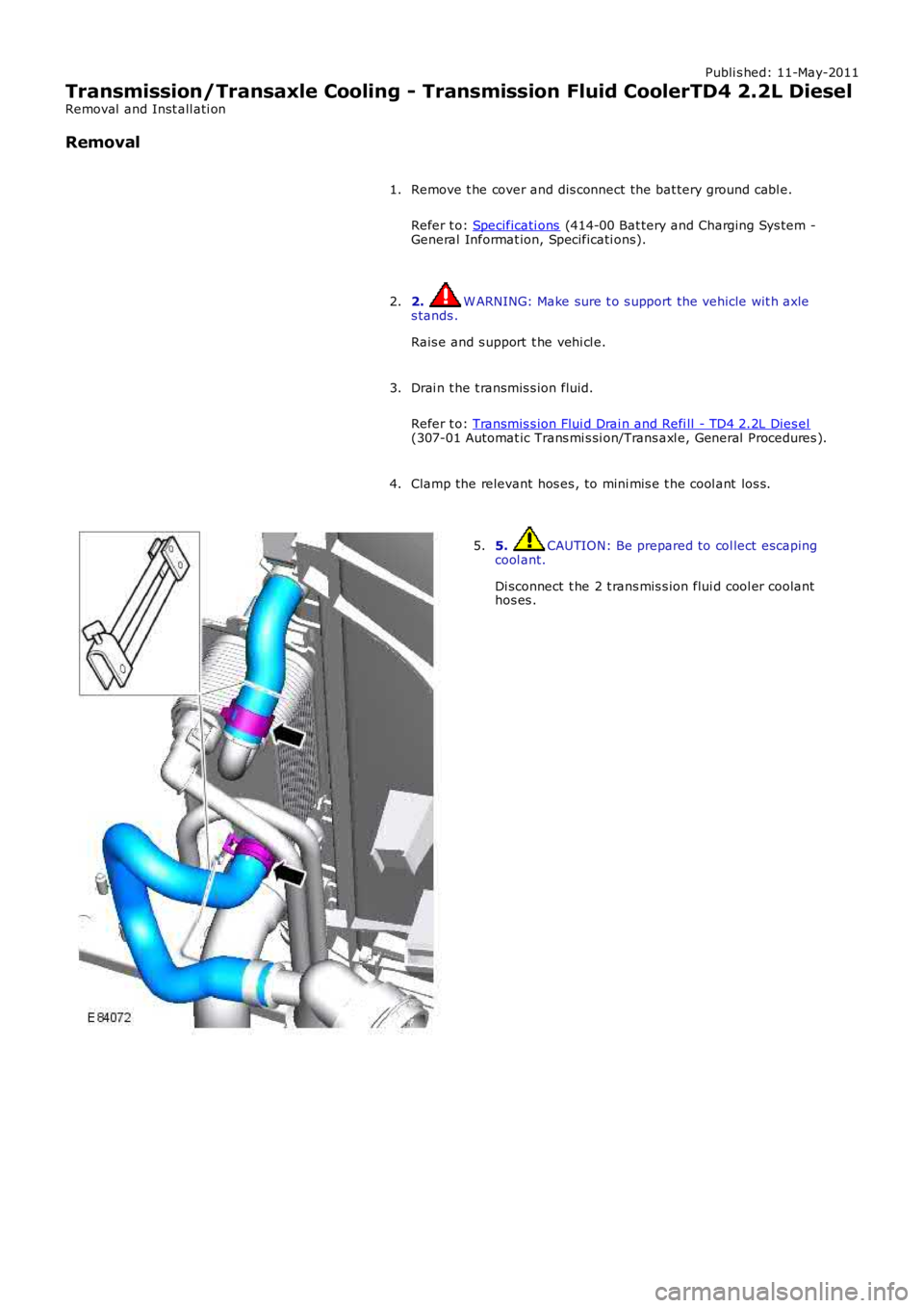
Clamp the relevant hos es , to mini mis e t he cool ant los s.
4. 5. CAUTION: Be prepared to col lect escaping
cool ant.
Di sconnect t he 2 t rans mis s ion flui d cool er coolant
hos es .
5.
Page 1645 of 3229
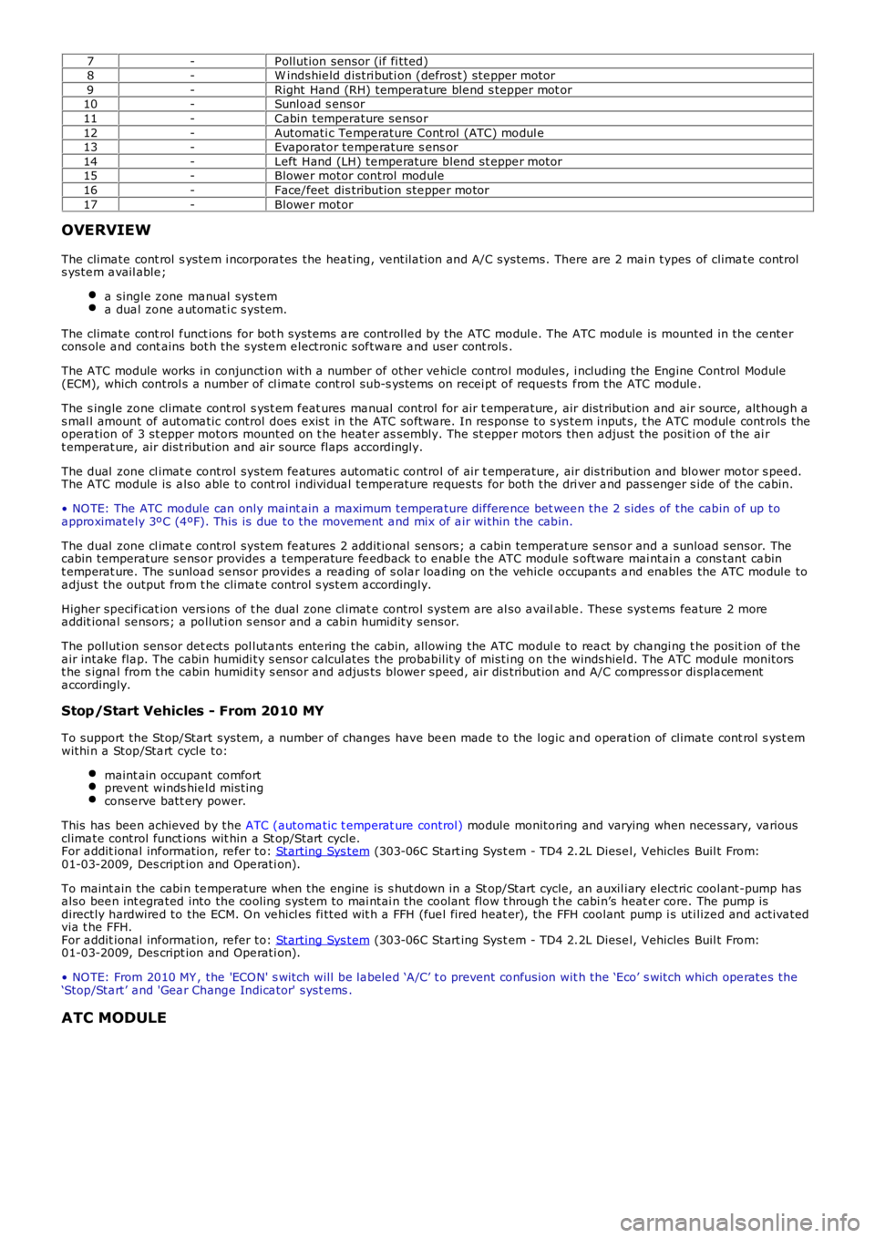
7-P ollution sensor (if fi tted)8-W indshie ld distri buti on (defrost) ste pper motor9-Right Hand (RH) tempera ture ble nd s tepper mot or10-Sunload s ens or11-Cabin temperature se nsor12-Automati c Te mpe rature Cont rol (ATC) modul e13-Evaporator te mpe rature s ens or14-Left Hand (LH) te mpe rature blend st eppe r motor15-Blowe r motor control module16-Face/feet dis tribution ste ppe r motor17-Blowe r motor
OVERVIEW
The clima te cont rol s yste m i ncorpora tes the hea ting, ve ntila tion and A/C systems. There are 2 mai n types of clima te controls yste m a vail able ;
a single z one ma nual sys tema dua l zone a utomati c system.
The clima te cont rol f unct ions for bot h systems a re controlle d by the ATC modul e. The ATC module is mounted in the ce nte rcons ole a nd cont ains bot h the syste m e lectronic sof twa re a nd user cont rols .
The ATC module works in conjunction wi th a number of othe r ve hicle control module s, i ncluding the Engine Control Module(ECM), which control s a number of cl ima te control sub-s yste ms on recei pt of reques ts f rom the ATC module .
The s ingle zone climate cont rol s yst em f eat ures ma nual control for air t empera ture , air dist ribution and air source, although as mal l amount of aut oma tic control does exis t in the ATC softwa re. In re sponse to s yste m i nput s, t he ATC module cont rols theopera tion of 3 st epper motors mounted on t he heat er as sembly. The st eppe r motors then a djust the positi on of the ai rt emperat ure, air dist ribution and air source flaps accordingly.
The dual zone cl imat e control system fe atures a utomati c control of air t empera ture , air dis tribution and blower motor s pee d.The ATC module is a lso able to cont rol i ndividua l te mpe rature re que sts for both the dri ver a nd pass enger s ide of the cabin.
• NO TE: The ATC module can only maint ain a maximum tempera ture dif fere nce bet wee n the 2 side s of the cabin of up toa pproximate ly 3ºC (4ºF). This is due to the moveme nt a nd mix of a ir wi thin the cabin.
The dual zone cl imat e control system fe atures 2 additional sens ors; a cabin temperature se nsor and a sunload sensor. Thecabin temperature se nsor provides a temperature fe edback to e nabl e the ATC module s oftware mai ntai n a cons tant ca bint emperat ure. The sunloa d se nsor provide s a rea ding of s ola r loa ding on the vehicle occupants a nd enables the ATC module toa djus t the output from t he clima te control s yste m a ccordingly.
Higher specif icat ion vers ions of t he dual zone cl imat e control system are al so a vailable . These syst ems fea ture 2 morea ddit iona l se nsors; a polluti on s ensor and a cabin humidity sensor.
The pollution sensor det ects pol luta nts ente ring the cabin, allowing the ATC modul e to rea ct by cha ngi ng t he posit ion of thea ir intake fla p. The cabin humidi ty s ensor ca lcul ates the probability of misti ng on the winds hiel d. The ATC module monitorst he s igna l from t he cabin humidi ty s ensor and a djus ts blowe r speed, air dis tribution and A/C compress or di spla cementa ccordingly.
Stop/Start Vehicles - From 2010 MY
To support the Stop/Start system, a number of changes have be en made to the logic and opera tion of climate cont rol s yst emwithi n a Stop/Sta rt cycle to:
maint ain occupant comfortpreve nt winds hie ld mistingconse rve batt ery power.
This has bee n achieved by the ATC (automa tic t emperat ure control) module monitoring and varying when nece ssary, va riousclima te control funct ions wit hin a St op/Start cycle.For a ddit iona l inf ormation, re fer to: Starting Sys tem (303-06C Start ing Syst em - TD4 2.2L Diese l, Vehicles Buil t From:01-03-2009, Des cript ion and Ope rati on).
To maint ain the cabi n te mpe rature when the engine is s hut down in a St op/Start cycle, an a uxil iary electric coolant-pump hasa lso bee n int egra ted into the cooling system to mai ntai n the coolant flow t hrough t he cabi n’s heat er core. The pump isdirectly hardwire d to the ECM. O n ve hicl es fi tted wit h a FFH (fue l fired heat er), the FFH coolant pump i s uti lize d and activa tedvia t he FFH.For a ddit iona l inf ormation, re fer to: Starting Sys tem (303-06C Start ing Syst em - TD4 2.2L Diese l, Vehicles Buil t From:01-03-2009, Des cript ion and Ope rati on).
• NO TE: From 2010 MY , the 'ECO N' s witch will be la bele d ‘A/C’ t o prevent confusion wit h the ‘Eco’ s witch which ope rate s the‘Stop/Sta rt’ a nd 'Gea r Change Indica tor' syst ems .
ATC MODULE