Page 2702 of 3229
Release the LH and RH suspension arms, as the subframe is lowered,
and tie them aside. 21.
22. NOTE: Do not disassemble further if the component is removed for
access only.
Remove the catalyst support bracket. 22.
Remove the steering gear. 23.
Installation
Install the steering gear.
Torque: 105 Nm1.
Using the special tool, support the subframe. 2.
3.
CAUTION: Install all the bolts finger tight before final tightening.
Raise the front subframe to allow installation of the suspension arms and the bolts. 3.
Install the LH and RH suspension arms as the subframe is raised. 4.
Install the stabilizer bar. 5.
6.
CAUTION: Make sure that new bolts are installed.
Install the subframe cross-brace.
Torque: 45 Nm6.
7.
CAUTION: Make sure that new bolts are installed. 7.
Page 2703 of 3229
St a g e
1:
St a g e
2:
St a g e 1:
St a g e 2: Install the 2 support brackets.
Torque: 25 Nm
Install the
front
subframe.
Sp e c i a l
T ool (s ):
502-012
Torque:
140 Nm
240°
8.
Install the catalyst support bracket.
Torque: 10 Nm
9.
Install the fuel line. 10.
Install the purge line. 11.
Tighten bolt 1.
Torque:
140 Nm
45°Tighten bolt 2 to
Torque: 175 Nm
Tighten bolt 3 to
Torque: 175 Nm
12.
Secure the catalytic converters. 13.
14.
WARNING: Make sure that new nuts are installed.
Connect the LH and RH tie-rod end ball joints.
Torque: 105 Nm14.
Connect the steering gear pressure lines.
Torque: 25 Nm
15.
16.
WARNING: Make sure that new nuts are installed.
CAUTION: Make sure that the ball joint ball does not rotate.
Install the stabilizer link bar to the lower suspension arm, and tighten to 55 Nm (41
lb.ft) 16.
Secure the electrical harness. 17.
Page 2710 of 3229
6.
Repeat the above procedure on the opposite hand. 7.
8.
Repeat the above procedure on the opposite hand. 9.
10.
WARNING: Make sure to support the vehicle with axle
stands.
Raise and support the vehicle. 10.
Remove both rear wheels and tires.
Refer to: Wheel and Tire
(204-04 Wheels and Tires, Removal and
Installation). 11.
If installed, remove the rear suspension height sensor.
Refer to: Rear Suspension Height Sensor
(204-05 Vehi cl e Dynami c
Suspension, Removal and Installation). 12.
Remove the rear muffler.
Refer to: Exhaus t Sys t em
(309-00B Exhaus t Sys t em - TD4 2.2L
Diesel, Removal and Installation). 13.
Page 2715 of 3229

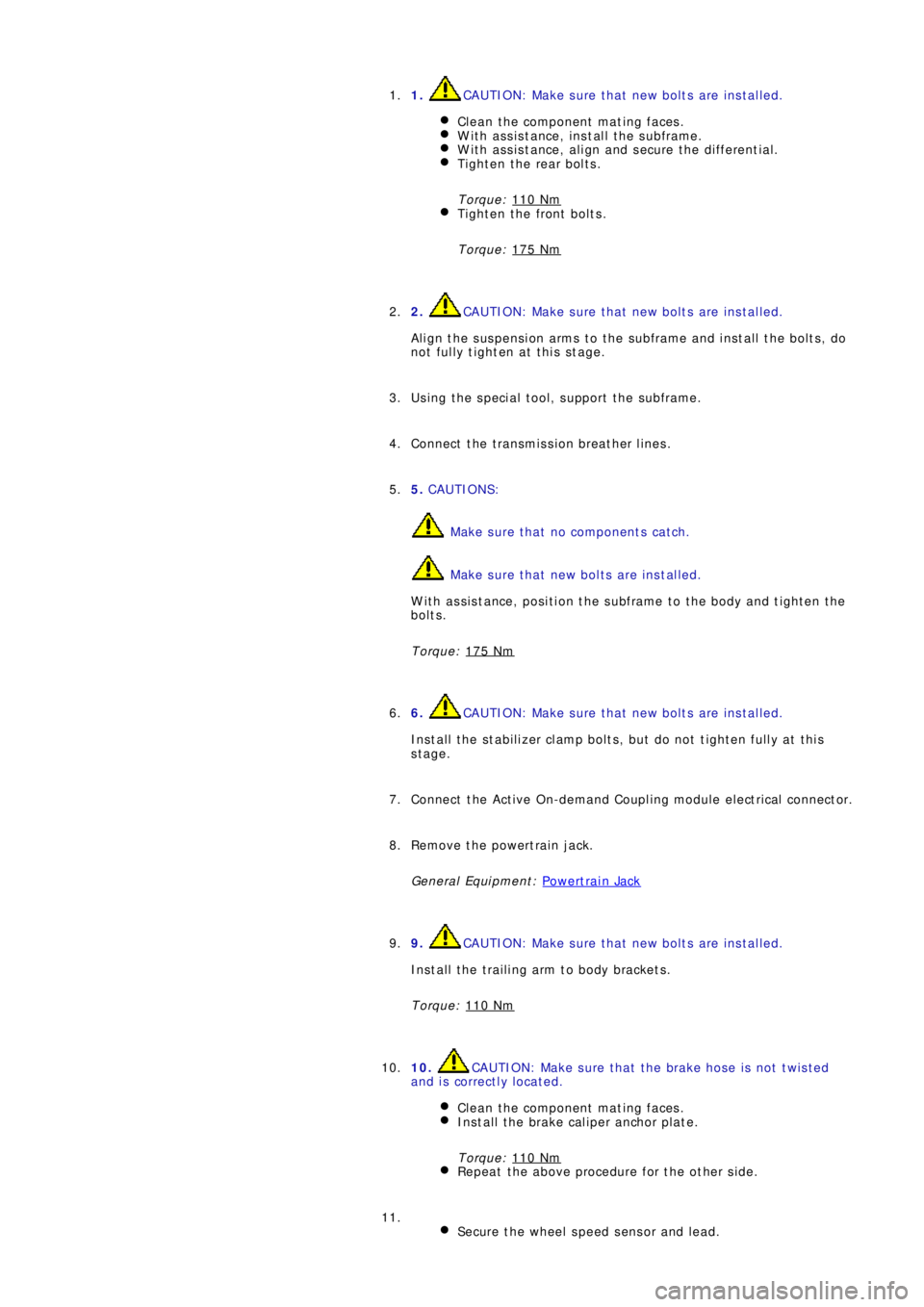
1. CAUTION: Make sure that new bolts are installed.
Clean the component mating faces.
With assistance, install the subframe.With assistance, align and secure the differential.Tighten the rear bolts.
Torque: 110 Nm
Tighten the front bolts.
Torque: 175 Nm
1.
2.
CAUTION: Make sure that new bolts are installed.
Align the suspension arms to the subframe and install the bolts, do
not fully tighten at this stage. 2.
Using the special tool, support the subframe. 3.
Connect the transmission breather lines. 4.
5. CAUTIONS:
Make sure that no components catch.
Make sure that new bolts are installed.
With assistance, position the subframe to the body and tighten the
bolts.
Torque: 175 Nm
5.
6.
CAUTION: Make sure that new bolts are installed.
Install the stabilizer clamp bolts, but do not tighten fully at this
stage. 6.
Connect the Active On-demand Coupling module electrical connector. 7.
Re mo ve t he p o we rt ra i n j a ck.
General Equi pment : P o w e rt ra i n Ja ck
8.
9.
CAUTION: Make sure that new bolts are installed.
Install the trailing arm to body brackets.
Torque: 110 Nm9.
10.
CAUTION: Make sure that the brake hose is not twisted
and is correctly located.
Clean the component mating faces.
Install the brake caliper anchor plate.
Torque: 110 Nm
Repeat the above procedure for the other side.
10.
Secure the wheel speed sensor and lead.
11.
Page 2716 of 3229

Torque: 5 NmSecure the lead in the clips.Repeat the above procedure for the other side.
LH side: Connect the ride height sensor electrical connector. 12.
Position and secure the rear shock absorbers.
Install both mass dampers.
Torque: 25 Nm
Repeat the above procedure for the other side.
13.
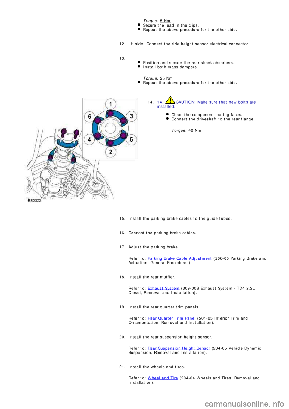
14. CAUTION: Make sure that new bolts are
installed.
Clean the component mating faces.
Connect the driveshaft to the rear flange.
Torque: 40 Nm
14.
Install the parking brake cables to the guide tubes. 15.
Connect the parking brake cables. 16.
Adjust the parking brake.
Refer to: Parking Brake Cable Adjustment
(206-05 Parki ng Brake and
Act uat i on, General Procedures ). 17.
Install the rear muffler.
Refer to: Exhaus t Sys t em
(309-00B Exhaus t Sys t em - TD4 2.2L
Diesel, Removal and Installation). 18.
Install the rear quarter trim panels.
Refer to: Rear Quarter Trim Panel
(501-05 Int eri or Tri m and
Ornament at i on, Removal and Ins t al lat i on). 19.
Install the rear suspension height sensor.
Refer to: Rear Suspension Height Sensor
(204-05 Vehi cl e Dynami c
Suspension, Removal and Installation). 20.
Install the wheels and tires.
Refer to: Wheel and Tire
(204-04 Wheels and Tires, Removal and
Installation). 21.
Page 2717 of 3229
22. CAUTION: Nuts and bolts must be tightened with the
weight of the vehicle on the suspension.
Tighten the stabilizer bar clamp bolts.
Torque: 60 Nm22.
23.
CAUTION: Nuts and bolts must be tightened with the
weight of the vehicle on the suspension.
Tighten the supsension arms to the subframe.
Torque: 175 Nm
During installation, do not tighten the nuts and bolts until
the 4 wheel alignment procedure has been carried out.
23.
Carry out a complete vehicle geometry check and adjustment. 24.
Page 2745 of 3229

25
Quick start
R
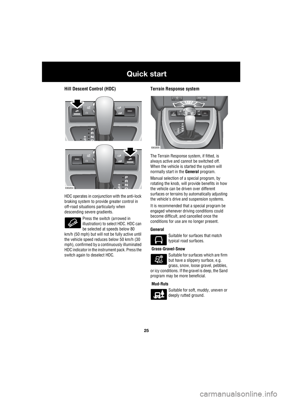
Hill Descent Control (HDC)
HDC operates in conjunction with the anti-lock
braking system to provide greater control in
off-road situations particularly when
descending severe gradients.
Press the switch (arrowed in
illustration) to se lect HDC. HDC can
be selected at speeds below 80
km/h (50 mph) but will not be fully active until
the vehicle speed reduc es below 50 km/h (30
mph), confirmed by a c ontinuously illuminated
HDC indicator in the instrument pack. Press the
switch again to deselect HDC.
Terrain Response system
The Terrain Response sy stem, if fitted, is
always active and cannot be switched off.
When the vehicle is st arted the system will
normally start in the General program.
Manual selection of a special program, by
rotating the knob, will pr ovide benefits in how
the vehicle can be driven over different
surfaces or terrains by automatically adjusting
the vehicle's drive and suspension systems.
It is recommended that a special program be
engaged whenever driving conditions could
become difficult, a nd cancelled once the
conditions for use are no longer present.
General Suitable for surfaces that match
typical road surfaces.
Grass-Gravel-Snow Suitable for surfaces which are firm
but have a slippery surface, e.g.
grass, snow, loose gravel, pebbles,
or icy conditions. If the gravel is deep, the Sand
program may be more beneficial.
Mud-Ruts Suitable for soft, muddy, uneven or
deeply rutted ground.
E83204
E83205
E80903
Page 2757 of 3229

37
Introduction
R
DATA RECORDING
Service data recording
Service data recorders in your vehicle are
capable of collecting and storing diagnostic
information about your vehicle. This potentially
includes information about the performance or
status of various syst ems and modules in the
vehicle such as engine, throttle, steering or
brakes.
In order to properly di agnose and service your
vehicle, Land Rover a nd service and repair
facilities may access vehicle diagnostic
information through a direct connection to
your vehicle.
Event data recording
Event data recorders are capable of collecting
and storing data during a crash or near-crash
event. The recorded information may assist in
the investigation of such an event. The
modules may record information about both
the vehicle and the oc cupants, potentially
including information such as:
• How various systems in your vehicle were
operating.
• Whether or not the driver and passenger
seat belts were buckled.
• How far, if at all, the driver was depressing
the accelerator and/or the brake pedal.
• How fast the vehicle was travelling.
• Where the driver was positioning the
steering wheel.
To access this information special equipment
must be connected directly to the recording
modules. Land Rover do not access event data
recorder information without obtaining
consent, unless pursuan t to court order or
where required by law enforcement, other
government authorities or third parties acting
with lawful authority. Other parties may seek to access the
information independe ntly of Land Rover.
DISABILITY MODIFICATIONS
Occupants with disabili ties which may require
modification of the vehi cle must contact a Land
Rover Dealer/Authorised Repairer before any
modifications are made.
PARTS AND ACCESSORIES
WARNINGS
The fitting of non-approved parts and
accessories, or the carrying out of
non-approved alterations or
conversions, may be dangerous and could
affect the safety of th e vehicle and occupants
and also invalidate the terms and conditions of
the vehicle warranty.
Land Rover will not accept any liability
for death, personal injury or damage to
property which may occur as a direct
result of fitment of non-approved accessories
or the carrying out of non-approved
conversions to La nd Rover vehicles.
Land Rover strongly advise against
making any modifications to the
suspension or steering system. This
could seriously affe ct the handling and
stability of the vehicle leading to loss of control
or roll-over.