2006 LAND ROVER FRELANDER 2 fuel cap
[x] Cancel search: fuel capPage 1455 of 3229
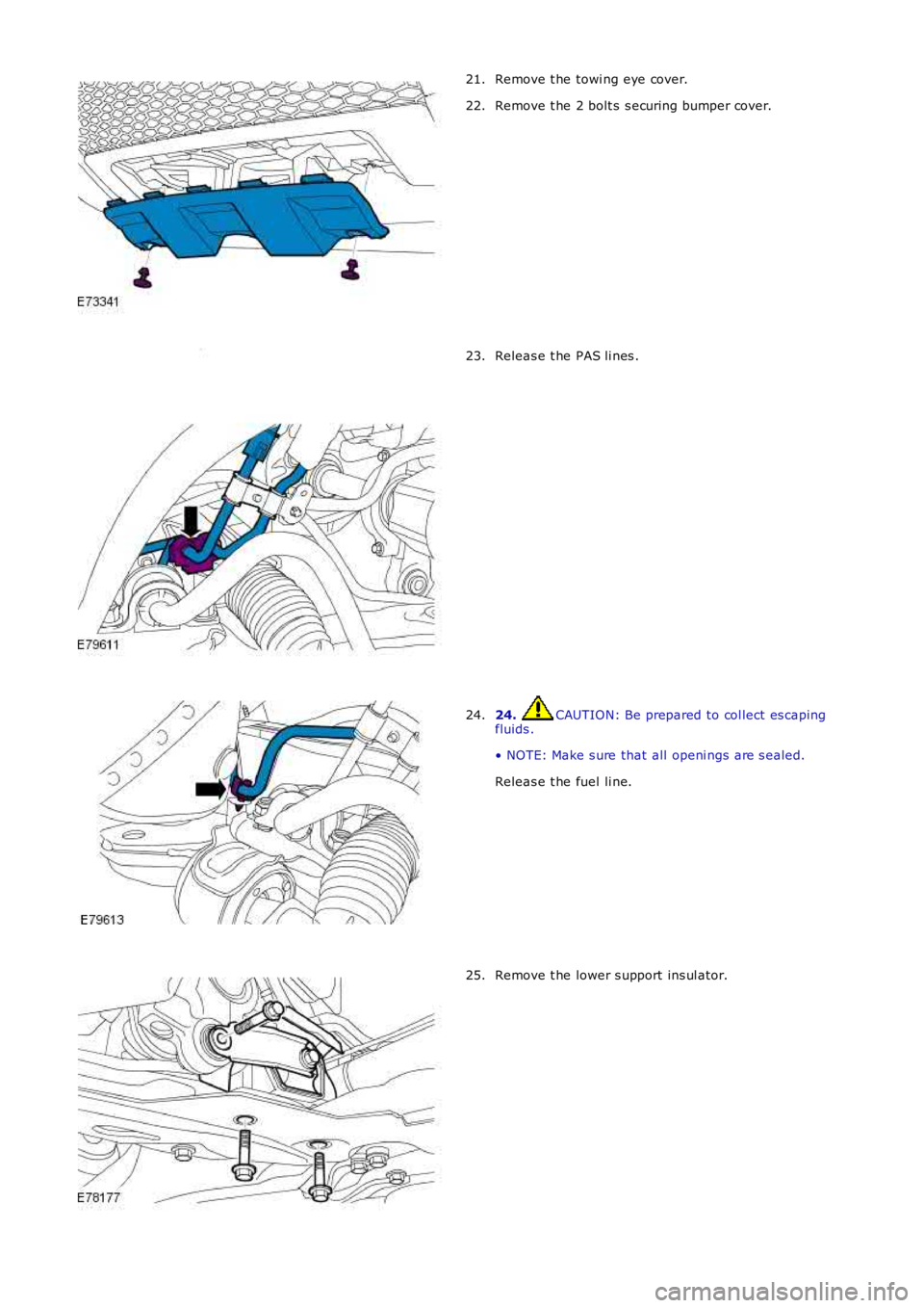
Remove t he towi ng eye cover.
21.
Remove t he 2 bolt s s ecuring bumper cover.
22. Releas e t he PAS li nes .
23. 24. CAUTION: Be prepared to col lect es caping
fluids .
• NOTE: Make s ure that all openi ngs are s ealed.
Releas e t he fuel li ne.
24. Remove t he lower s upport ins ul ator.
25.
Page 1515 of 3229
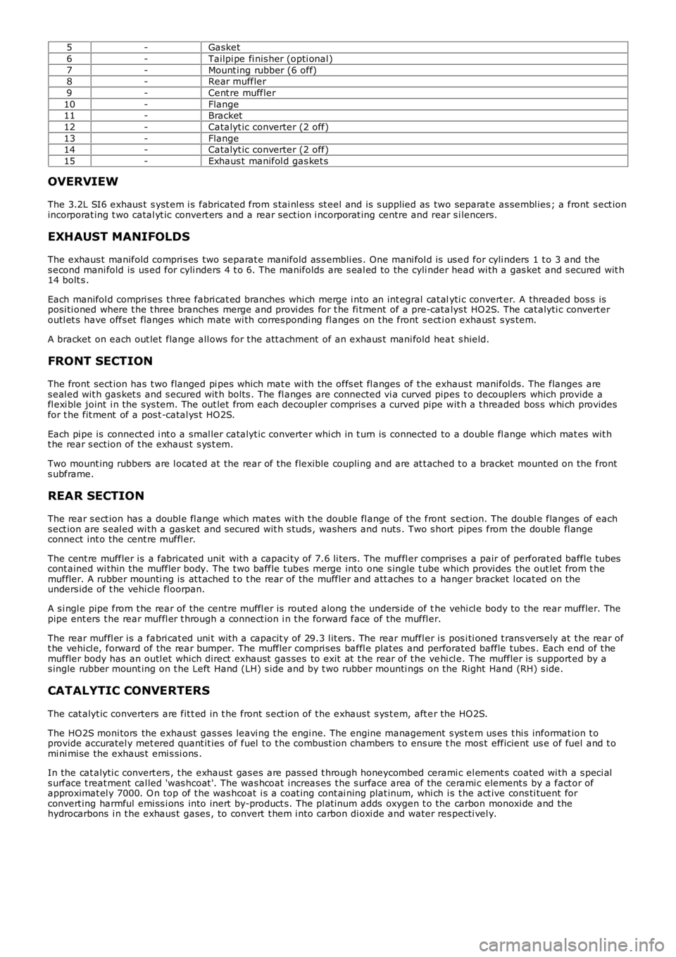
5-Gasket
6-Tailpi pe fi nis her (opti onal )
7-Mount ing rubber (6 off)8-Rear muffler
9-Cent re muffler
10-Flange11-Bracket
12-Catalyt ic converter (2 off)
13-Flange14-Catalyt ic converter (2 off)
15-Exhaus t manifol d gas ket s
OVERVIEW
The 3.2L SI6 exhaus t s yst em i s fabricated from s tai nl ess st eel and is s upplied as two separat e as sembl ies ; a front s ect ionincorporat ing t wo catal yt ic convert ers and a rear sect ion i ncorporat ing centre and rear s i lencers.
EXHAUST MANIFOLDS
The exhaus t manifold compri s es two separat e manifold as s embli es . One mani fol d is us ed for cyli nders 1 t o 3 and thes econd mani fold is us ed for cyli nders 4 t o 6. The manifolds are s eal ed to the cyli nder head wi th a gas ket and s ecured wit h14 bolt s .
Each manifol d compri ses t hree fabri cat ed branches whi ch merge i nto an int egral cat alyti c convert er. A threaded bos s isposi ti oned where t he t hree branches merge and provi des for t he fi tment of a pre-catalys t HO2S. The cat alyti c convert eroutl et s have offs et flanges which mat e wi th corres pondi ng fl anges on t he front s ect ion exhaus t s ys tem.
A bracket on each out let flange all ows for t he att achment of an exhaus t mani fold heat s hield.
FRONT SECTION
The front sect ion has t wo flanged pi pes which mat e wi th the offs et fl anges of t he exhaus t manifol ds. The flanges ares eal ed wit h gas ket s and s ecured wit h bolt s . The fl anges are connected vi a curved pipes t o decouplers which provide afl exi ble joint i n the sys tem. The out let from each decoupl er compris es a curved pipe wit h a t hreaded bos s whi ch providesfor t he fit ment of a pos t -catal ys t HO2S.
Each pi pe is connect ed i nt o a smal ler catalyt ic converter whi ch in t urn is connected to a doubl e fl ange which mat es wit ht he rear s ect ion of t he exhaus t s ys t em.
Two mount ing rubbers are l ocat ed at the rear of the flexible coupli ng and are at t ached t o a bracket mounted on the fronts ubframe.
REAR SECTION
The rear s ect ion has a doubl e fl ange which mat es wit h t he doubl e fl ange of the front s ect ion. The doubl e flanges of eachs ect ion are s eal ed wi th a gas ket and s ecured wit h s tuds , washers and nuts . Two s hort pipes from the double fl angeconnect int o the cent re muffl er.
The cent re muffler is a fabricated unit wit h a capaci ty of 7.6 li ters. The muffl er compris es a pair of perforat ed baffle t ubescont ained wi thin the muffler body. The t wo baffle tubes merge into one s ingle t ube which provi des the out let from t hemuffler. A rubber mounti ng is at t ached t o t he rear of the muffler and att aches t o a hanger bracket l ocat ed on theunders ide of t he vehi cl e fl oorpan.
A s i ngl e pipe from t he rear of the centre muffl er is rout ed along t he unders ide of the vehi cl e body to the rear muffler. Thepipe ent ers t he rear muffl er t hrough a connect ion i n t he forward face of the muffl er.
The rear muffl er i s a fabri cat ed uni t wit h a capacit y of 29.3 l it ers . The rear muffler i s pos i ti oned t rans vers ely at t he rear oft he vehi cl e, forward of the rear bumper. The muffler compri ses baffl e plat es and perforated baffle tubes . Each end of t hemuffler body has an outl et which direct exhaus t gas ses to exit at t he rear of t he vehi cl e. The muffler is support ed by as ingle rubber mount ing on t he Left Hand (LH) s ide and by t wo rubber mounti ngs on the Right Hand (RH) s ide.
CATALYTIC CONVERTERS
The cat alyt ic converters are fit t ed in t he front s ect ion of t he exhaus t s ys t em, aft er the HO2S.
The HO2S moni tors the exhaust gas s es leavi ng t he engi ne. The engine management s ys t em us es t hi s informat ion t oprovide accuratel y met ered quant it ies of fuel t o t he combus t ion chambers t o ens ure the mos t efficient us e of fuel and t omi ni mi se the exhaus t emi s si ons .
In the cat alyti c convert ers , t he exhaus t gas es are pas s ed t hrough honeycombed ceramic el ement s coated wi th a s peci als urface t reat ment cal led 'was hcoat '. The was hcoat i ncreas es t he s urface area of the cerami c element s by a fact or ofapproximat el y 7000. O n top of t he was hcoat i s a coat ing cont ai ning plat inum, whi ch is t he act ive cons ti tuent forconvert ing harmful emi ss i ons into inert by-product s. The pl at inum adds oxygen t o the carbon monoxi de and thehydrocarbons i n t he exhaus t gases , to convert t hem i nto carbon di oxi de and water respecti vel y.
Page 1529 of 3229
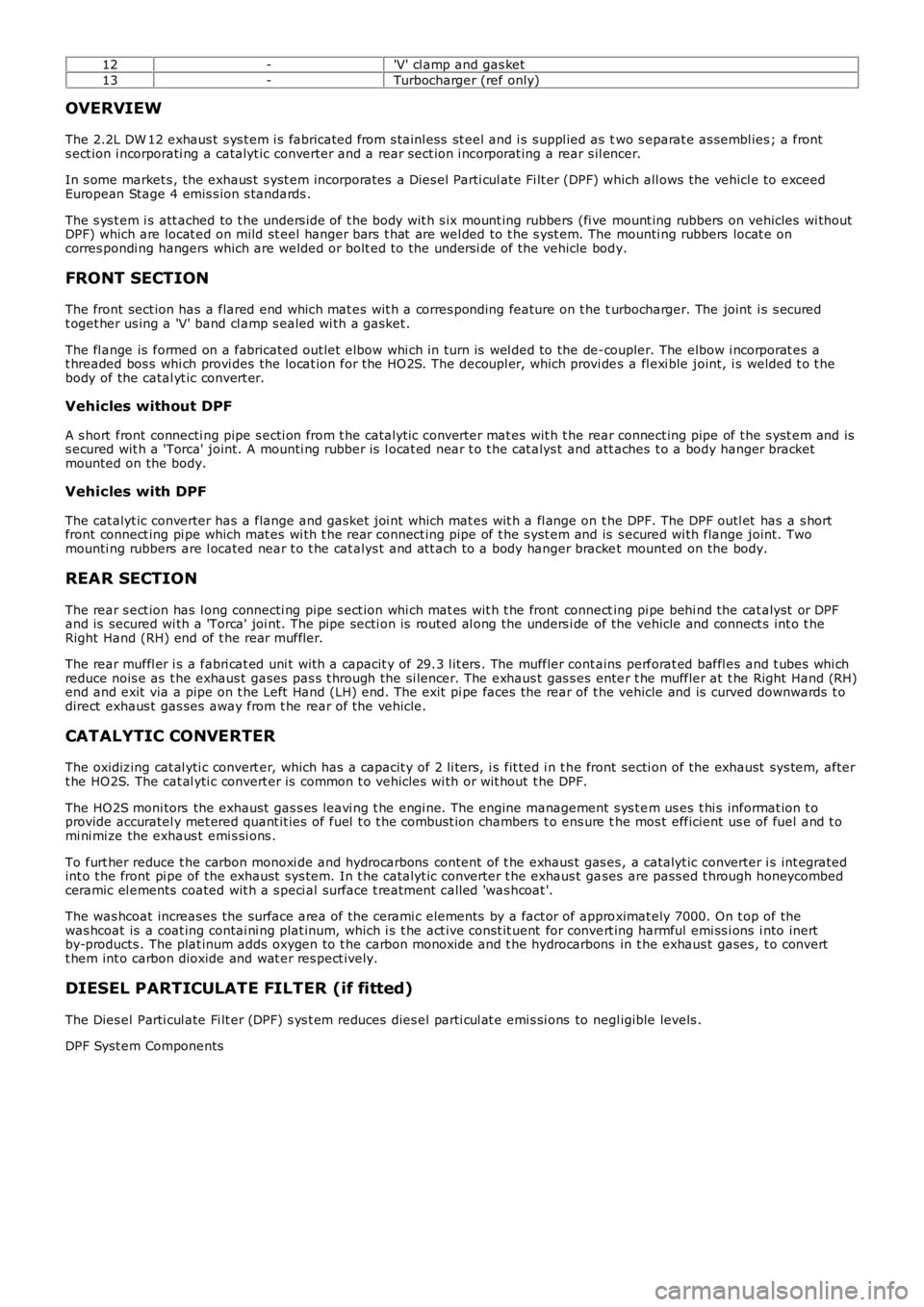
12-'V' cl amp and gas ket
13-Turbocharger (ref only)
OVERVIEW
The 2.2L DW 12 exhaus t s ys t em i s fabricated from s tainl ess st eel and i s s uppl ied as two s eparat e as sembl ies ; a fronts ect ion i ncorporati ng a catalyt ic converter and a rear sect ion i ncorporat ing a rear s il encer.
In s ome market s , the exhaus t s yst em incorporates a Dies el Parti cul ate Fi lt er (DPF) which all ows the vehicl e to exceedEuropean Stage 4 emis s ion s tandards .
The s ys t em i s att ached to t he unders ide of t he body wit h s ix mount ing rubbers (fi ve mount ing rubbers on vehicles wi thoutDPF) which are locat ed on mild st eel hanger bars t hat are wel ded to t he s yst em. The mounti ng rubbers locat e oncorres pondi ng hangers which are welded or bolt ed to the unders i de of the vehicle body.
FRONT SECTION
The front sect ion has a flared end which mat es wit h a corres ponding feature on t he turbocharger. The joint i s s ecuredt oget her us ing a 'V' band cl amp s ealed wi th a gasket .
The fl ange is formed on a fabricated out let elbow whi ch in turn is wel ded to the de-coupler. The elbow i ncorporat es at hreaded bos s whi ch provi des the locat ion for the HO2S. The decoupl er, which provi des a fl exi ble joint, i s welded t o t hebody of the catal yt ic convert er.
Vehicles without DPF
A s hort front connecti ng pipe s ecti on from t he catalyt ic converter mat es wit h t he rear connect ing pipe of t he s yst em and iss ecured wit h a 'Torca' joint. A mounti ng rubber is l ocat ed near t o t he cat alys t and att aches t o a body hanger bracketmounted on the body.
Vehicles with DPF
The cat alyt ic converter has a flange and gasket joi nt which mat es wit h a fl ange on the DPF. The DPF outl et has a s hortfront connect ing pi pe which mat es wi th t he rear connect ing pipe of t he s yst em and is s ecured wi th flange joint. Twomounti ng rubbers are l ocated near t o t he cat alys t and att ach to a body hanger bracket mount ed on the body.
REAR SECTION
The rear s ect ion has l ong connecti ng pipe s ect ion whi ch mat es wit h t he front connecting pi pe behi nd the cat alyst or DPFand is secured wi th a 'Torca' joi nt. The pipe secti on is routed al ong the unders i de of the vehicle and connect s int o t heRight Hand (RH) end of t he rear muffl er.
The rear muffl er i s a fabri cat ed uni t wit h a capacit y of 29.3 l it ers . The muffler cont ains perforat ed baffl es and t ubes whi chreduce nois e as t he exhaus t gases pas s t hrough the si lencer. The exhaus t gas s es enter t he muffler at t he Right Hand (RH)end and exit via a pipe on t he Left Hand (LH) end. The exit pi pe faces the rear of the vehicle and is curved downwards t odirect exhaus t gas ses away from t he rear of the vehicle.
CATALYTIC CONVERTER
The oxidizing cat al yti c convert er, which has a capacit y of 2 li ters, i s fit ted i n t he front secti on of the exhaust sys tem, aftert he HO2S. The cat al yti c convert er is common t o vehicles wi th or wit hout t he DPF.
The HO2S moni tors the exhaust gas s es leavi ng t he engi ne. The engine management s ys t em us es t hi s informat ion t oprovide accuratel y met ered quant it ies of fuel t o t he combus t ion chambers t o ens ure the mos t efficient us e of fuel and t omi ni mi ze the exhaus t emi s si ons .
To furt her reduce t he carbon monoxi de and hydrocarbons content of t he exhaus t gas es , a catalyt ic converter i s int egratedint o t he front pi pe of the exhaust sys tem. In t he catalyt ic converter t he exhaus t gases are pass ed t hrough honeycombedceramic el ements coated wit h a s peci al surface t reatment call ed 'was hcoat '.
The was hcoat increas es the surface area of t he cerami c elements by a fact or of approximat ely 7000. On t op of thewas hcoat is a coat ing contai ni ng plat inum, which i s t he act ive const it uent for convert ing harmful emi ss i ons i nto inertby-products . The plat inum adds oxygen to t he carbon monoxide and t he hydrocarbons in t he exhaus t gases , t o convertt hem int o carbon dioxide and wat er res pect ively.
DIESEL PARTICULATE FILTER (if fitted)
The Dies el Parti cul ate Fi lt er (DPF) s ys t em reduces dies el parti cul at e emi s si ons to negl igible levels .
DPF Syst em Components
Page 1549 of 3229
Publi s hed: 27-May-2011
Fuel System - General Information - Fuel Tank Draining
General Procedures
• W ARNINGS:
Place t he vehi cle i n a wel l vent ilat ed, quarant ined area and arrange ' No Smoki ng/Petrol Fumes ' si gns about t hevehi cl e.
Do not carry or operate cel lular phones when working on or near any fuel rel at ed component s. Hi ghl y flammablevapors are al ways pres ent and may ignit e. Fai lure to foll ow t hese ins truct ions may res ul t in pers onal injury.
Do not s moke or carry li ght ed t obacco or open flame of any type when worki ng on or near any fuel relat edcomponents . Hi ghl y fl ammable vapors are al ways present and may i gnit e. Fail ure t o foll ow t hes e i nst ructi ons may res ult inpers onal i njury.
The s pil ling of fuel is unavoi dabl e duri ng thi s operati on. Ens ure t hat all neces s ary precauti ons are t aken to preventfi re and expl os i on.
CAUTION: Before dis connecti ng or removing component s , ens ure the area around t he joint faces and connect ions areclean. Pl ug open connect ions t o prevent cont aminat ion.
• NOTE: It is pos s ible that up t o 18 l it res of fuel may be left i n t he tank after drai ning.
Open t he fuel fill er door and remove the cap.1.
Di sconnect t he bat t ery ground cable.
Refer t o: Specificati ons (414-01 Bat tery, Mount ing and Cables ,Speci fi cat ions ).
2.
Connect t he fuel t ank drain equipment ground cable t o t he vehi cle.3.
4. W ARNING: Fuel may s t ill be present i n t he fuel tank afterdrai ning.
Remove t he fuel from t he fuel t ank, via the fil ler neck, us ing t he fuelt ank draining equi pment . Fol low the manufact urer's operati ngi ns t ructi ons .
4.
To i nst all , revers e t he removal procedure.5.
Page 1550 of 3229
Publi s hed: 11-May-2011
Fuel System - General Information - Fuel System BleedingTD4 2.2L Diesel
General Procedures
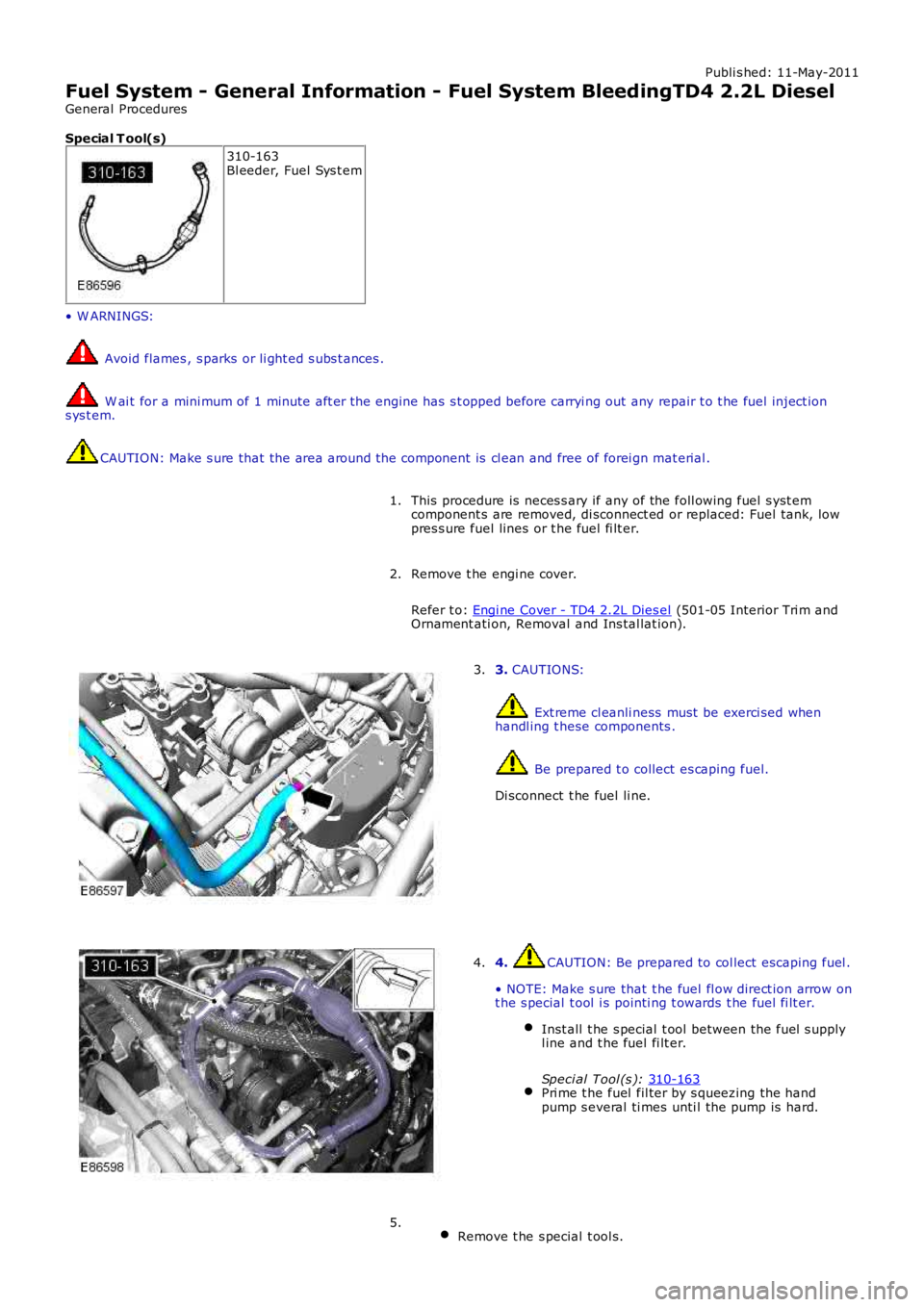
Special T ool(s) 310-163
Bl eeder, Fuel Sys t em
• W ARNINGS: Avoid flames , s parks or li ght ed s ubs t ances .
W ai t for a mini mum of 1 minute aft er the engine has s t opped before carryi ng out any
repair t o t he fuel inject ion
s ys t em. CAUTION: Make s ure that the area around t he component is cl ean and free of forei gn m
at erial .
This procedure is neces s ary if any of the foll owing fuel s yst em
component s are removed, di sconnect ed or replaced: Fuel tank, low
pres s ure fuel lines or t he fuel fi lt er.
1.
Remove t he engi ne cover.
Refer t o: Engi ne Cover - TD4 2.2L Dies el (501-05 Interior Tri m and
Ornament ati on, Removal and Ins tal lat ion).
2. 3.
CAUTIONS: Ext reme cl eanli ness must be exerci sed when
handl ing t hese components . Be prepared t o collect es caping fuel.
Di sconnect t he fuel li ne.
3. 4. CAUTION: Be prepared to col lect escaping fuel .
• NOTE: Make s ure that t he fuel fl ow direct ion arrow on
t he s pecial t ool i s pointi ng t owards t he fuel fi lt er.
Inst all t he s pecial t ool between the fuel s upply
l ine and t he fuel fi lt er.
Speci al Tool (s ): 310-163 Pri me t he fuel fil ter by s queezing the hand
pump s everal ti mes unti l the pump is hard. 4.
Remove t he s pecial t ool s. 5.
Page 1552 of 3229
Publi s hed: 11-May-2011
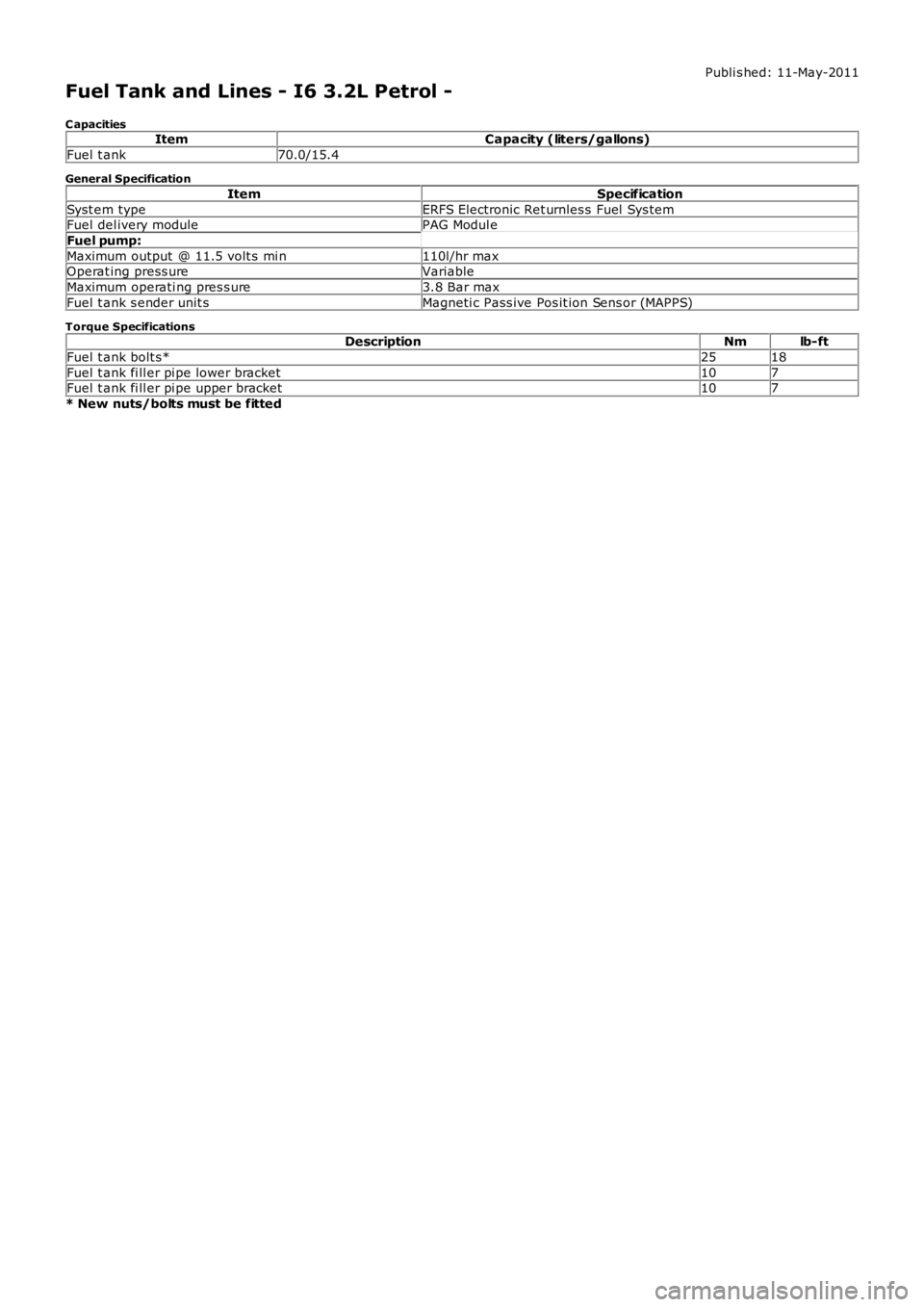
Fuel Tank and Lines - I6 3.2L Petrol -
C apacitiesItemCapacity (liters/gallons)
Fuel t ank70.0/15.4
General Specification
ItemSpecification
Syst em typeERFS Electronic Ret urnles s Fuel Sys temFuel del ivery modulePAG Modul e
Fuel pump:
Maximum output @ 11.5 volt s mi n110l/hr maxOperat ing press ureVariable
Maximum operati ng pres s ure3.8 Bar max
Fuel t ank s ender unit sMagneti c Pass ive Pos it ion Sens or (MAPPS)
Torque SpecificationsDescriptionNmlb-ft
Fuel t ank bolt s*2518
Fuel t ank fi ll er pi pe lower bracket107Fuel t ank fi ll er pi pe upper bracket107
* New nuts/bolts must be fitted
Page 1554 of 3229
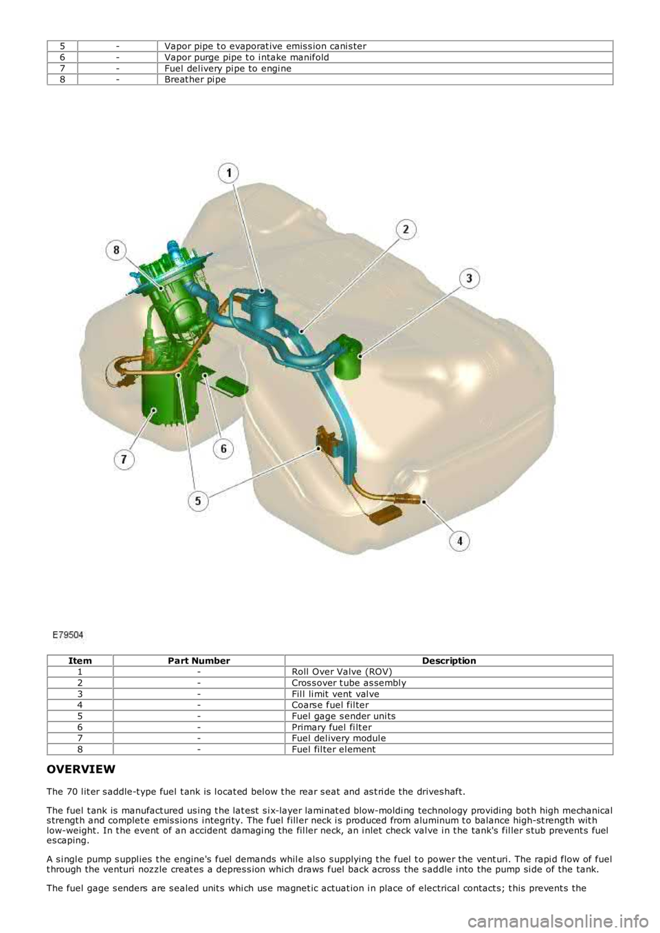
5-Vapor pipe t o evaporat ive emis s ion cani s ter
6-Vapor purge pipe t o i ntake manifold
7-Fuel del ivery pi pe to engi ne8-Breat her pi pe
ItemPart NumberDescription1-Roll Over Valve (ROV)
2-Cros s over t ube as sembl y
3-Fil l li mit vent val ve4-Coars e fuel fil ter
5-Fuel gage s ender uni ts
6-Primary fuel fi lt er7-Fuel del ivery modul e
8-Fuel fil ter el ement
OVERVIEW
The 70 l it er s addle-t ype fuel t ank is l ocat ed bel ow t he rear s eat and as t ri de the drives haft.
The fuel t ank is manufact ured us ing t he lat est s i x-layer lami nat ed blow-moldi ng technol ogy providing bot h high mechanicals trengt h and complet e emis s ions i ntegri ty. The fuel fill er neck i s produced from aluminum t o balance high-st rength wit hlow-weight. In t he event of an accident damagi ng the fil ler neck, an i nlet check valve i n t he tank's fil ler s tub prevent s fueles caping.
A s i ngl e pump s uppl ies t he engine's fuel demands whil e als o s upplying t he fuel t o power the vent uri. The rapi d flow of fuelt hrough the venturi nozzle creat es a depres s ion whi ch draws fuel back across the s addle i nto the pump si de of the tank.
The fuel gage s enders are s ealed unit s whi ch us e magnet ic actuat ion i n place of electrical contact s; t his prevent s the
Page 1555 of 3229

problem of chemi cal contami nat ion of el ect ri cal components .
To meet on-board refuel ing vapor recovery (ORVR) requi rements , t he fuel t ank and as soci ated component s are des i gned t omi ni mi ze fuel vapor los s duri ng refuel ing. This i s achi eved by prevent ing fuel vapor from t he fuel t ank vent ing direct ly tot he atmos phere. Ins t ead fuel vapor is di rected into the evaporati ve emis s ion (EVAP) canis t er where i t is s t ored beforebeing purged at i ntervals to the engine’s intake mani fold.For addit ional informat ion, refer t o: Evaporat ive Emi s si ons (303-13 Evaporat ive Emi ss ions , Descripti on and Operat ion).
Roll Over Valve (ROV)
The ROV i s connected vi a pipes t o a l iquid vapour separat or. The s eparator i s connected via a pipe to t he t ank breatheroutl et in t he pump module fl ange. The ROV contai ns a non-ret urn val ve, whi ch cl oses i n t he event of t he vehi cl eoverturning, prevent ing l iquid fuel escaping from the tank via the breat her pi pe.