2006 LAND ROVER FRELANDER 2 fuel cap
[x] Cancel search: fuel capPage 1184 of 3229
Publi s hed: 11-May-2011
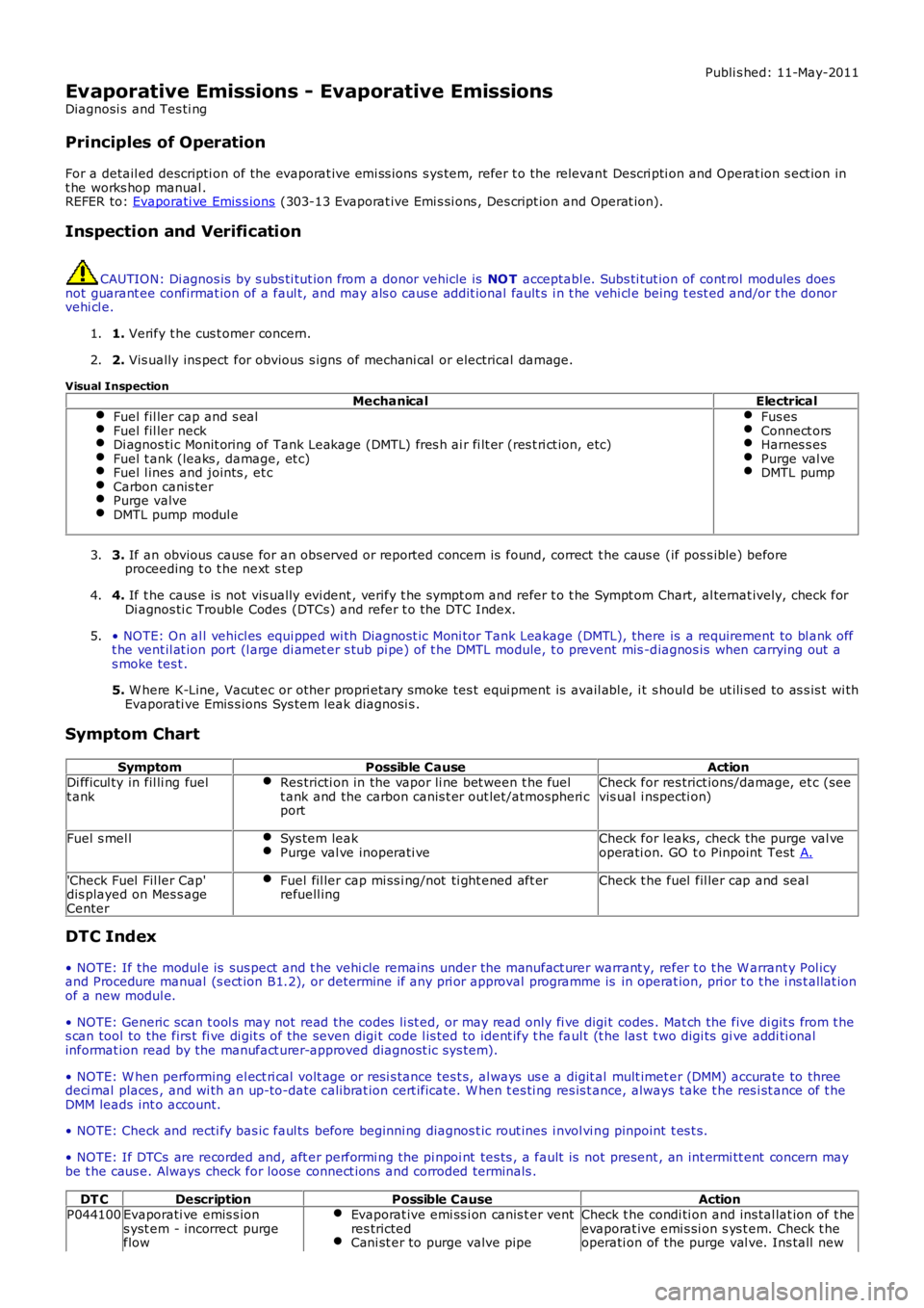
Evaporative Emissions - Evaporative Emissions
Diagnosi s and Tes ti ng
Principles of Operation
For a detail ed descripti on of the evaporat ive emi ss ions s ys tem, refer t o the relevant Descri pti on and Operat ion s ect ion int he works hop manual .REFER to: Evaporati ve Emis s ions (303-13 Evaporat ive Emi s si ons , Des cript ion and Operat ion).
Inspection and Verification
CAUTION: Di agnos is by s ubs ti tut ion from a donor vehicle is NO T acceptabl e. Subs ti tut ion of cont rol modules doesnot guarant ee confirmat ion of a faul t, and may als o caus e addit ional fault s i n t he vehi cl e being t est ed and/or t he donorvehi cl e.
1. Verify t he cus t omer concern.1.
2. Vis ually ins pect for obvious s igns of mechani cal or electrical damage.2.
Visual InspectionMechanicalElectrical
Fuel fil ler cap and s ealFuel fil ler neckDi agnos ti c Monit oring of Tank Leakage (DMTL) fres h ai r fi lt er (res t ri ct ion, etc)Fuel t ank (leaks , damage, et c)Fuel l ines and joints , et cCarbon canis terPurge valveDMTL pump modul e
Fus esConnect orsHarnes s esPurge val veDMTL pump
3. If an obvious cause for an obs erved or report ed concern is found, correct t he caus e (if pos s ible) beforeproceeding t o t he next s t ep3.
4. If t he caus e is not vis ually evi dent , verify t he sympt om and refer t o t he Sympt om Chart, al ternat ively, check forDi agnos ti c Trouble Codes (DTCs) and refer t o t he DTC Index.4.
• NOTE: On al l vehicl es equi pped wi th Diagnost ic Moni tor Tank Leakage (DMTL), there is a requirement to bl ank offt he vent il at ion port (l arge di amet er s tub pi pe) of t he DMTL module, t o prevent mis -diagnos is when carrying out as moke tes t .
5. W here K-Line, Vacut ec or other propri etary smoke tes t equi pment is avail abl e, i t s houl d be ut ili s ed to as s is t wi thEvaporati ve Emis s ions Sys tem leak diagnosi s .
5.
Symptom Chart
SymptomPossible CauseActionDi fficul ty in fil li ng fuelt ankRes tricti on in the vapor li ne bet ween t he fuelt ank and the carbon canis t er out let/atmospheri cport
Check for res trict ions/damage, et c (seevis ual i nspecti on)
Fuel s mel lSys tem leakPurge val ve inoperati veCheck for leaks, check the purge val veoperati on. GO t o Pinpoint Test A.
'Check Fuel Fil ler Cap'dis played on Mes s ageCenter
Fuel fil ler cap mi ss i ng/not ti ght ened aft errefuell ingCheck t he fuel fil ler cap and seal
DTC Index
• NOTE: If the modul e is sus pect and t he vehi cle remains under the manufact urer warrant y, refer t o t he W arrant y Pol icyand Procedure manual (s ect ion B1.2), or determine if any pri or approval programme is in operat ion, pri or t o t he i ns t allat ionof a new modul e.
• NOTE: Generic scan t ool s may not read the codes li st ed, or may read only fi ve digit codes . Mat ch the five di git s from t hes can tool to the firs t fi ve di git s of the seven digi t code l is ted to ident ify t he faul t (t he las t t wo digi ts gi ve addi ti onalinformat ion read by the manufact urer-approved diagnost ic s ys tem).
• NOTE: W hen performing el ect ri cal volt age or resi s tance tes t s, al ways us e a digit al mult imet er (DMM) accurate to threedeci mal places , and wi th an up-to-date cali brat ion cert ificate. W hen t es ti ng res is t ance, always take t he res i st ance of t heDMM leads int o account.
• NOTE: Check and recti fy bas ic faul ts before beginni ng diagnos t ic rout ines i nvol vi ng pinpoint t es t s.
• NOTE: If DTCs are recorded and, aft er performi ng the pi npoi nt tes ts , a fault is not present , an int ermi tt ent concern maybe t he caus e. Always check for loose connect ions and corroded terminals .
DT CDescriptionPossible CauseActionP044100Evaporati ve emis s ions yst em - incorrect purgeflow
Evaporat ive emi ss i on canis t er ventres trictedCani st er to purge valve pipe
Check t he condi ti on and ins tal lat ion of t heevaporat ive emi s si on s ys t em. Check t heoperati on of the purge val ve. Ins tall new
Page 1185 of 3229
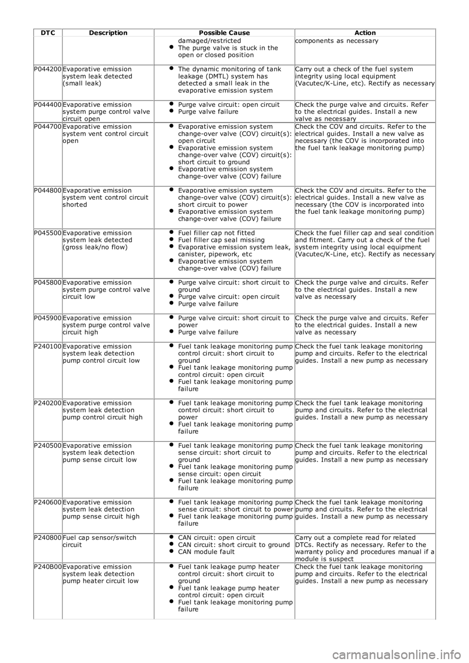
DT CDescriptionPossible CauseAction
damaged/res trictedThe purge valve is st uck in theopen or clos ed pos it ion
components as neces sary
P044200Evaporati ve emis s ions yst em leak detected(s mall leak)
The dynami c monit oring of t ankleakage (DMTL) s ys t em hasdet ect ed a s mal l leak in theevaporat ive emi ss i on sys t em
Carry out a check of t he fuel s ys t emint egrit y us ing l ocal equi pment(Vacutec/K-Line, etc). Recti fy as neces sary
P044400Evaporati ve emis s ions yst em purge cont rol valvecircui t open
Purge valve circui t: open circui tPurge valve fai lureCheck t he purge valve and ci rcuit s. Referto the el ect ri cal guides . Ins tal l a newval ve as neces s aryP044700Evaporati ve emis s ions yst em vent cont rol circui topen
Evaporat ive emi ss i on sys t emchange-over valve (COV) circui t(s ):open ci rcuitEvaporat ive emi ss i on sys t emchange-over valve (COV) circui t(s ):short ci rcuit t o groundEvaporat ive emi ss i on sys t emchange-over valve (COV) fai lure
Check t he COV and ci rcuit s. Refer t o t heelectrical gui des . Ins t all a new val ve asneces s ary (the COV is incorporated intothe fuel tank l eakage monit ori ng pump)
P044800Evaporati ve emis s ions yst em vent cont rol circui ts hort ed
Evaporat ive emi ss i on sys t emchange-over valve (COV) circui t(s ):short ci rcuit t o powerEvaporat ive emi ss i on sys t emchange-over valve (COV) fai lure
Check t he COV and ci rcuit s. Refer t o t heelectrical gui des . Ins t all a new val ve asneces s ary (the COV is incorporated intothe fuel tank l eakage monit ori ng pump)
P045500Evaporati ve emis s ions yst em leak detected(gros s leak/no flow)
Fuel fi ll er cap not fit tedFuel fi ll er cap s eal mis s ingEvaporat ive emi ss i on sys t em l eak,canis t er, pipework, et cEvaporat ive emi ss i on sys t emchange-over valve (COV) fai lure
Check t he fuel fil ler cap and seal condi ti onand fi tment . Carry out a check of t he fuels ys t em i ntegri ty us i ng local equipment(Vacutec/K-Line, etc). Recti fy as neces sary
P045800Evaporati ve emis s ions yst em purge cont rol valvecircui t low
Purge valve circui t: s hort circui t togroundPurge valve circui t: open circui tPurge valve fai lure
Check t he purge valve and ci rcuit s. Referto the el ect ri cal guides . Ins tal l a newval ve as neces s ary
P045900Evaporati ve emis s ions yst em purge cont rol valvecircui t high
Purge valve circui t: s hort circui t topowerPurge valve fai lure
Check t he purge valve and ci rcuit s. Referto the el ect ri cal guides . Ins tal l a newval ve as neces s ary
P240100Evaporati ve emis s ions yst em leak detecti onpump control ci rcuit l ow
Fuel t ank l eakage moni toring pumpcont rol ci rcuit : s hort circuit togroundFuel t ank l eakage moni toring pumpcont rol ci rcuit : open ci rcuitFuel t ank l eakage moni toring pumpfail ure
Check t he fuel t ank leakage moni toringpump and circui ts . Refer t o t he elect ricalguides. Ins tall a new pump as neces s ary
P240200Evaporati ve emis s ions yst em leak detecti onpump control ci rcuit high
Fuel t ank l eakage moni toring pumpcont rol ci rcuit : s hort circuit topowerFuel t ank l eakage moni toring pumpfail ure
Check t he fuel t ank leakage moni toringpump and circui ts . Refer t o t he elect ricalguides. Ins tall a new pump as neces s ary
P240500Evaporati ve emis s ions yst em leak detecti onpump s ens e circuit low
Fuel t ank l eakage moni toring pumpsens e circui t: s hort circui t togroundFuel t ank l eakage moni toring pumpsens e circui t: open circui tFuel t ank l eakage moni toring pumpfail ure
Check t he fuel t ank leakage moni toringpump and circui ts . Refer t o t he elect ricalguides. Ins tall a new pump as neces s ary
P240600Evaporati ve emis s ions yst em leak detecti onpump s ens e circuit hi gh
Fuel t ank l eakage moni toring pumpsens e circui t: s hort circui t to powerFuel t ank l eakage moni toring pumpfail ure
Check t he fuel t ank leakage moni toringpump and circui ts . Refer t o t he elect ricalguides. Ins tall a new pump as neces s ary
P240800Fuel cap s ens or/s wi tchcircui tCAN circuit : open circuitCAN circuit : s hort circui t to groundCAN module fault
Carry out a complete read for relat edDTCs. Recti fy as neces sary. Refer t o t hewarrant y poli cy and procedures manual i f amodule i s s uspectP240B00Evaporati ve emis s ions yst em leak detecti onpump heat er circui t low
Fuel t ank l eakage pump heat ercont rol ci rcuit : s hort circuit togroundFuel t ank l eakage pump heat ercont rol ci rcuit : open ci rcuitFuel t ank l eakage moni toring pumpfail ure
Check t he fuel t ank leakage moni toringpump and circui ts . Refer t o t he elect ricalguides. Ins tall a new pump as neces s ary
Page 1186 of 3229
1
2
3
1
2
3
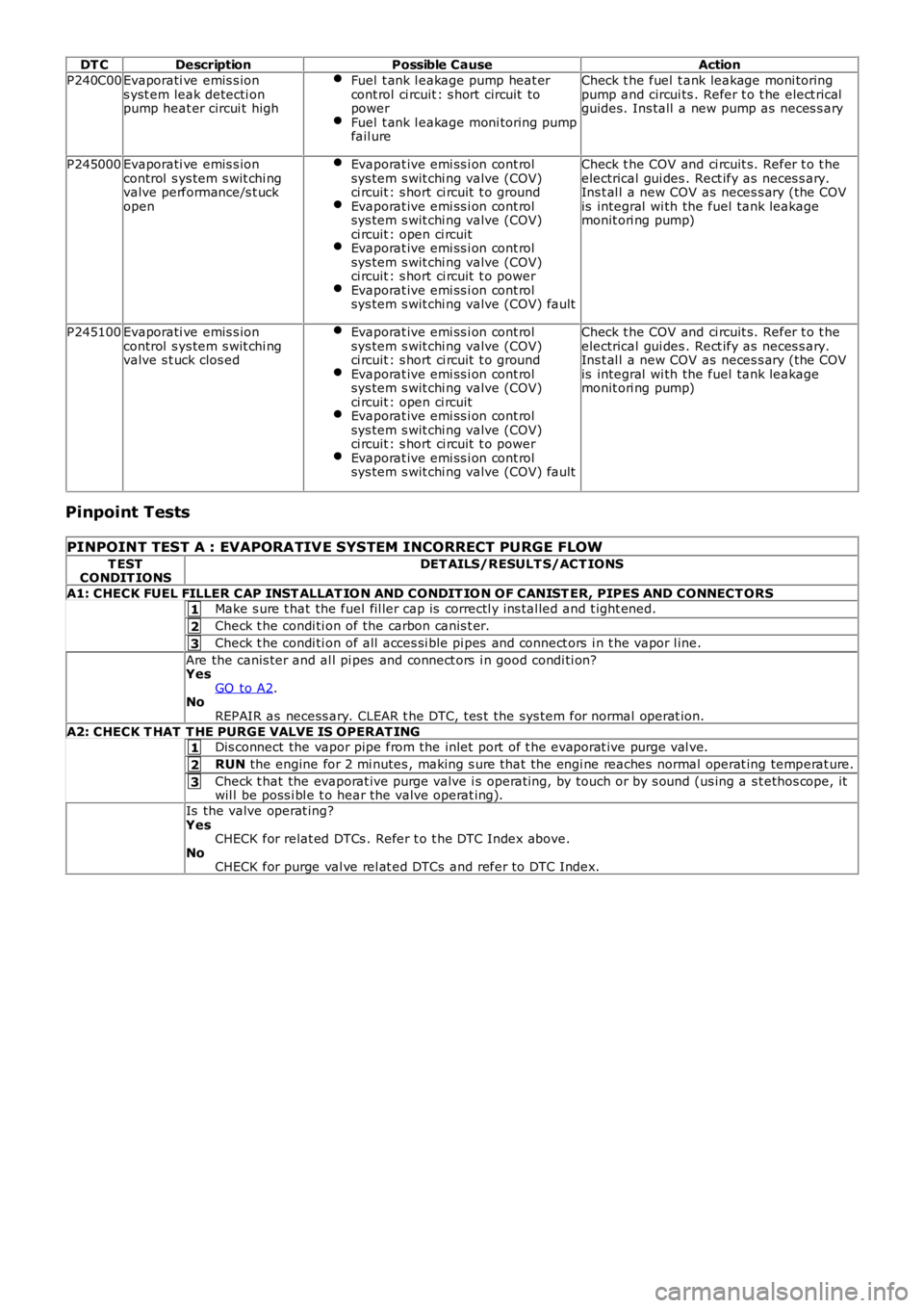
DT CDescriptionPossible CauseAction
P240C00Evaporati ve emis s ions yst em leak detecti onpump heat er circui t high
Fuel t ank l eakage pump heat ercont rol ci rcuit : s hort circuit topowerFuel t ank l eakage moni toring pumpfail ure
Check t he fuel t ank leakage moni toringpump and circui ts . Refer t o t he elect ricalguides. Ins tall a new pump as neces s ary
P245000Evaporati ve emis s ioncontrol s ys tem s wit chi ngvalve performance/s t uckopen
Evaporat ive emi ss i on cont rolsys tem s wit chi ng valve (COV)ci rcuit : s hort ci rcuit t o groundEvaporat ive emi ss i on cont rolsys tem s wit chi ng valve (COV)ci rcuit : open ci rcuitEvaporat ive emi ss i on cont rolsys tem s wit chi ng valve (COV)ci rcuit : s hort ci rcuit t o powerEvaporat ive emi ss i on cont rolsys tem s wit chi ng valve (COV) fault
Check t he COV and ci rcuit s. Refer t o t heelectrical gui des . Rect ify as neces s ary.Ins t al l a new COV as neces s ary (the COVis integral wi th the fuel tank leakagemonit ori ng pump)
P245100Evaporati ve emis s ioncontrol s ys tem s wit chi ngvalve s t uck clos ed
Evaporat ive emi ss i on cont rolsys tem s wit chi ng valve (COV)ci rcuit : s hort ci rcuit t o groundEvaporat ive emi ss i on cont rolsys tem s wit chi ng valve (COV)ci rcuit : open ci rcuitEvaporat ive emi ss i on cont rolsys tem s wit chi ng valve (COV)ci rcuit : s hort ci rcuit t o powerEvaporat ive emi ss i on cont rolsys tem s wit chi ng valve (COV) fault
Check t he COV and ci rcuit s. Refer t o t heelectrical gui des . Rect ify as neces s ary.Ins t al l a new COV as neces s ary (the COVis integral wi th the fuel tank leakagemonit ori ng pump)
Pinpoint Tests
PINPOINT TEST A : EVAPORATIVE SYSTEM INCORRECT PURGE FLOW
T ESTCONDIT IONSDET AILS/RESULT S/ACT IONS
A1: CHECK FUEL FILLER CAP INST ALLAT IO N AND CONDIT IO N OF CANIST ER, PIPES AND CONNECT ORSMake s ure t hat the fuel fil ler cap is correctl y ins tal led and t ight ened.
Check t he condi ti on of the carbon canis t er.
Check t he condi ti on of all acces si ble pi pes and connect ors i n t he vapor l ine.
Are the canis ter and al l pi pes and connect ors i n good condi ti on?YesGO to A2.NoREPAIR as necess ary. CLEAR t he DTC, tes t the sys tem for normal operat ion.
A2: CHECK T HAT T HE PURGE VALVE IS OPERAT INGDis connect the vapor pipe from the inlet port of t he evaporat ive purge val ve.
RUN the engine for 2 mi nutes , making s ure that the engi ne reaches normal operat ing temperat ure.
Check t hat the evaporat ive purge valve i s operat ing, by touch or by s ound (us ing a st ethos cope, itwil l be poss i bl e t o hear the valve operat ing).
Is the valve operat ing?YesCHECK for relat ed DTCs . Refer t o t he DTC Index above.NoCHECK for purge val ve rel at ed DTCs and refer to DTC Index.
Page 1205 of 3229
t he ignit ion t imingt he engi ne load.
The ECM moni tors the MAF s ens or for faul ts and can s t ore fault rel ated codes. Thes e can be ret ri eved us ing a Land Roverapproved diagnos t ic s yst em.
Int ake Air Temperat ure (IAT) Sens or
The IAT s ens or measures the temperat ure of t he i nt ake air entering t he engine. The sens or is a temperat ure dependantres is t or (t hermi st or). The thermis t or i s a NTC sens or element. The el ement resi s tance decreas es as t he s ens ort emperature increas es. The ECM suppli es the sens or wit h a 5V reference volt age and a ground and meas ures the returneds ignal as a t emperature.
The res is t ance i n t he s ens or changes wi th i ntake air t emperat ure. A l ow i nt ake air temperature wi ll res ult i n a hi gh vol tagebeing returned t o t he ECM and hi gh int ake ai r temperature wil l ret urn a low volt age reading of bet ween 0 - 5V.
The ECM moni tors the IAT s ens or for fault s and can s tore faul t relat ed codes . Thes e can be retrieved us ing a Land Roverapproved diagnos t ic s yst em. If the IAT s ensor fails , t he ECM us es a defaul t temperature val ue usi ng the fuel railpres s ure/t emperat ure s ensor.
Knock Sensors
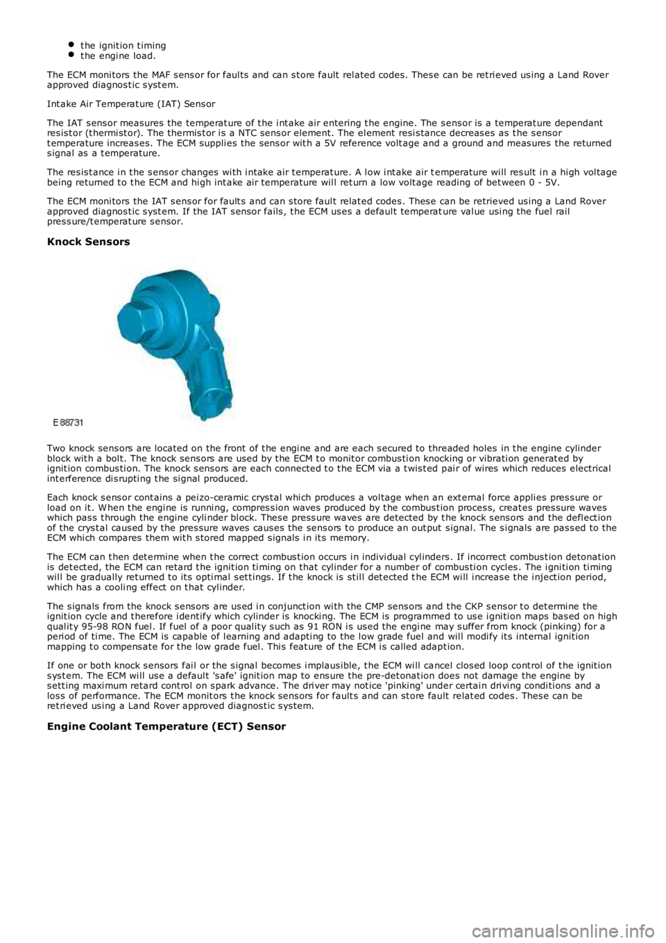
Two knock sens ors are located on the front of t he engi ne and are each s ecured to threaded holes in t he engine cylinderblock wit h a bol t. The knock sens ors are us ed by t he ECM t o monit or combus ti on knocking or vibrati on generat ed byignit ion combus ti on. The knock s ens ors are each connected t o t he ECM via a t wis t ed pai r of wires which reduces electricalint erference di s rupti ng t he si gnal produced.
Each knock s ens or cont ains a pei zo-ceramic crys t al whi ch produces a vol tage when an ext ernal force appli es pres s ure orload on it . W hen t he engi ne is runni ng, compres s ion waves produced by t he combus t ion proces s, creat es pres sure waveswhich pas s t hrough the engine cyli nder bl ock. Thes e press ure waves are detected by the knock s ens ors and the defl ect ionof the crys t al caus ed by the pres sure waves caus es the sens ors t o produce an out put s ignal. The s i gnals are pas s ed to theECM whi ch compares them wit h s tored mapped s ignal s i n it s memory.
The ECM can t hen det ermine when t he correct combus t ion occurs i n indivi dual cyl inders . If incorrect combus t ion detonat ionis det ect ed, the ECM can retard t he ignit ion ti ming on that cyl inder for a number of combus ti on cycl es . The i gni ti on ti mingwil l be gradually ret urned t o it s opti mal s et t ings. If t he knock is st il l det ected the ECM wi ll i ncreas e t he i nject ion period,which has a cooli ng effect on t hat cyl inder.
The s ignals from the knock s ens ors are us ed i n conjunct ion wi th the CMP sens ors and t he CKP s ens or t o det ermi ne theignit ion cycle and t herefore i dent ify which cylinder is knocki ng. The ECM is programmed to us e i gni ti on maps bas ed on highqual it y 95-98 RO N fuel . If fuel of a poor qual it y s uch as 91 RON i s us ed the engi ne may s uffer from knock (pinking) for aperi od of ti me. The ECM is capable of l earning and adapti ng to the l ow grade fuel and wil l modi fy it s int ernal ignit ionmapping t o compens at e for t he low grade fuel . Thi s feat ure of t he ECM i s called adapt ion.
If one or bot h knock s ensors fai l or the s ignal becomes i mplaus ible, t he ECM wi ll cancel clos ed loop cont rol of t he ignit ions ys t em. The ECM wi ll us e a defaul t 's afe' ignit ion map to ens ure the pre-det onat ion does not damage the engine bys ett ing maxi mum retard cont rol on s park advance. The dri ver may not ice 'pinking' under certai n dri vi ng condi ti ons and alos s of performance. The ECM monit ors t he knock s ens ors for fault s and can st ore fault relat ed codes . Thes e can beret ri eved us i ng a Land Rover approved diagnos t ic s ys tem.
Engine Coolant Temperature (ECT) Sensor
Page 1206 of 3229
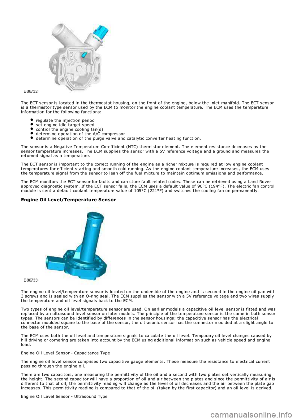
The ECT s ens or is locat ed i n t he thermost at hous ing, on t he front of the engine, below t he i nl et manifol d. The ECT s ens oris a t hermis t or type s ens or us ed by the ECM t o monit or the engine coolant t emperature. The ECM uses t he t emperatureinformat ion for the foll owi ng functi ons:
regulat e t he inject ion peri ods et engi ne idle target s peedcont rol t he engi ne cool ing fan(s )determine operat ion of t he A/C compres sordetermine operat ion of t he purge valve and catal yt ic convert er heat ing funct ion.
The s ens or is a Negat ive Temperat ure Co-efficient (NTC) thermis tor element . The element res is t ance decreas es as thes ens or t emperature increas es. The ECM suppli es the sens or wit h a 5V reference volt age and a ground and meas ures theret urned s ignal as a t emperature.
The ECT s ens or is important to the correct running of t he engi ne as a richer mixt ure i s required at low engi ne cool antt emperatures for efficient s tarti ng and s mooth cold running. As t he engi ne cool ant temperat ure i ncreas es , the ECM usest he temperat ure si gnal from the sens or to l ean off t he fuel mi xt ure to maint ai n optimum emis s ions and performance.
The ECM moni tors the ECT sens or for faul ts and can s t ore faul t rel at ed codes . These can be ret ri eved us ing a Land Roverapproved diagnos t ic s yst em. If the ECT sens or fail s, t he ECM us es a defaul t val ue of 90°C (194°F). The electric fan cont rolmodule i s s ent a default coolant temperat ure val ue of 105°C (221°F) and s wit ches t he cooling fan on permanent ly.
Engine Oil Level/Temperature Sensor
The engi ne oil l evel/t emperature s ens or is locat ed on t he unders ide of t he engi ne and is secured i n t he engi ne oil pan wi th3 s crews and i s s eal ed wi th an O-ring s eal. The ECM suppli es the s ens or wit h a 5V reference volt age and two wires s uppl yt he temperat ure and oi l level si gnal s back t o t he ECM.
Two t ypes of engine oi l level /t emperat ure s ensor are us ed. On earli er model s a capacit ive oi l level s ens or i s fit ted and wasrepl aced by an ul trasound l evel s ens or on l at er models . The principl e of the temperat ure s ens or i s t he s ame in bot h s ens ort ypes . The sens ors can be i dent ified by di fferences in t he s ens or housi ngs ; t he capacit ive s ensor has t he electricalconnector moulded s quare t o t he bas e of the s ens or, t he ult ras oni c s ens or has the connect or moulded at a s li ght angle tot he bas e of t he s ens or.
The ECM us es both the oi l l evel and t emperature s ignals t o calculat e t he oil level. Temporary oil level changes caus ed byhil l driving or cornering are taken i nt o account by t he ECM us ing addit ional informat ion s uch as vehi cl e s peed and engi neload.
Engi ne Oi l Level Sens or - Capacit ance Type
The engi ne oil l evel s ens or compris es t wo capaci ti ve gauge el ement s . Thes e meas ure the resi s tance to elect rical currentpass i ng through t he engine oi l.
There are t wo capacit ors , one meas uring t he permit ti vi ty of t he oil and a second with t wo pl at es s et verti cal ly meas uri ngt he hei ght . The s econd capaci tor wil l have a proport ion of oil and ai r bet ween t he plates and s i nce t he permit ti vi ty of ai r isdifferent t o t hat of oi l, t he permi tt ivit y readi ng wil l change as t he level of oi l decreas es and the ai r between t he plat e gapincreas es. This permi tt ivit y readi ng is compared t o t hat of the oi l (t aken by t he first capaci tor) and an oil level is derived.
Engi ne Oi l Level Sens or - Ult ras ound Type
Page 1215 of 3229
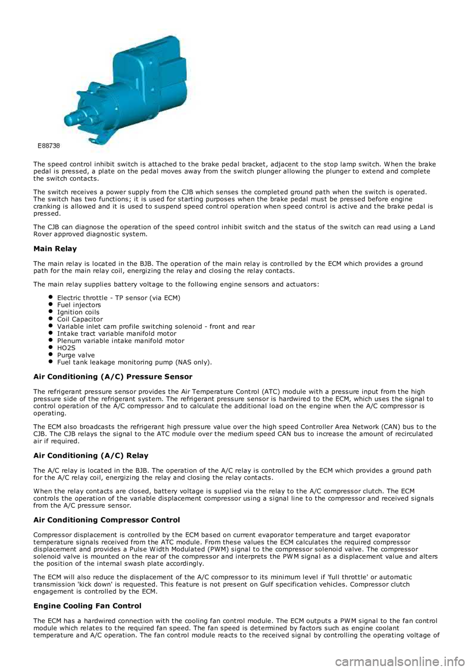
The s peed control inhibit swi tch i s att ached to t he brake pedal bracket , adjacent t o t he s top l amp s wit ch. W hen the brakepedal i s pres s ed, a pl ate on the pedal moves away from t he s wit ch plunger al lowing the pl unger to ext end and completet he swit ch contact s.
The s wit ch receives a power s upply from t he CJB which s enses the complet ed ground path when the s wi tch i s operated.The s wit ch has two functi ons ; it is us ed for s t art ing purpos es when the brake pedal mus t be pres s ed before engi necranking i s allowed and it is used t o s us pend speed cont rol operat ion when s peed cont rol i s act ive and t he brake pedal ispres s ed.
The CJB can diagnos e t he operat ion of t he speed control i nhibit s wi tch and t he s tat us of the s wi tch can read us ing a LandRover approved diagnost ic sys tem.
Main Relay
The main rel ay is l ocat ed in the BJB. The operati on of the mai n rel ay is cont roll ed by t he ECM which provi des a groundpath for the main relay coil , energi zing t he rel ay and cl osi ng t he rel ay cont act s.
The main rel ay suppli es bat t ery volt age to the foll owing engine s ensors and act uators:
Electric t hrot tl e - TP s ensor (via ECM)Fuel i njectorsIgni ti on coi lsCoil Capaci torVari abl e inl et cam profile swit ching sol enoi d - front and rearInt ake tract variable mani fol d mot orPlenum variable i ntake manifold motorHO2SPurge valveFuel t ank leakage monit oring pump (NAS onl y).
Air Conditioning (A/C) Pressure Sensor
The refri gerant pres sure s ens or provides t he Air Temperat ure Cont rol (ATC) module wit h a press ure input from t he highpres s ure s ide of t he refrigerant s ys t em. The refri gerant press ure s ens or is hardwired to the ECM, which us es t he s ignal t ocont rol operat ion of t he A/C compress or and to cal cul at e t he addit ional l oad on t he engi ne when t he A/C compress or isoperati ng.
The ECM al so broadcas ts the refrigerant high press ure val ue over t he high s peed Controller Area Network (CAN) bus t o t heCJB. The CJB relays the si gnal t o t he ATC module over t he medium speed CAN bus t o i ncreas e the amount of recircul at edair i f required.
Air Conditioning (A/C) Relay
The A/C rel ay is l ocat ed in the BJB. The operati on of the A/C relay i s cont roll ed by t he ECM whi ch provi des a ground pat hfor t he A/C rel ay coi l, energizi ng the relay and clos ing the relay cont acts .
W hen t he rel ay cont act s are clos ed, batt ery vol tage i s s uppl ied via the relay t o t he A/C compress or clut ch. The ECMcont rol s the operat ion of t he vari abl e dis placement compress or us ing a s i gnal li ne to t he compress or and received s ignalsfrom the A/C pres s ure sens or.
Air Conditioning Compressor Control
Compres s or di spl acement is cont roll ed by t he ECM bas ed on current evaporator t emperature and target evaporat ort emperature s ignals received from t he ATC module. From thes e values t he ECM calcul ates t he requi red compres s ordis placement and provi des a Puls e W idt h Modul ated (PW M) s i gnal t o t he compress or s olenoi d valve. The compress ors olenoi d valve i s mounted on the rear of t he compres s or and i nterprets the PW M s ignal as a dis placement val ue and alt erst he pos i ti on of the i nternal s wash plate accordi ngl y.
The ECM wi ll als o reduce t he dis placement of the A/C compres s or to i ts mini mum l evel i f 'ful l throt t le' or aut omati ct ransmis s ion 'ki ck down' is request ed. Thi s feat ure i s not pres ent on Gul f s pecificati on vehi cl es. Compress or clutchengagement is cont roll ed by t he ECM.
Engine Cooling Fan Control
The ECM has a hardwired connect ion wit h t he cooli ng fan cont rol module. The ECM output s a PW M s ignal to the fan cont rolmodule whi ch rel at es t o t he required fan s peed. The fan s peed is det ermi ned by factors s uch as engi ne coolantt emperature and A/C operati on. The fan cont rol module react s t o t he received s ignal by cont roll ing t he operat ing volt age of
Page 1339 of 3229
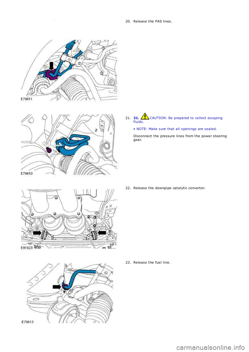
Releas e t he PAS li nes .
20. 21. CAUTION: Be prepared to col lect es caping
fluids .
• NOTE: Make s ure that all openi ngs are s ealed.
Di sconnect t he pres sure l ines from t he power s teeri ng
gear.
21. Releas e t he downpi pe cat alyti c convert er.
22. Releas e t he fuel li ne.
23.
Page 1444 of 3229
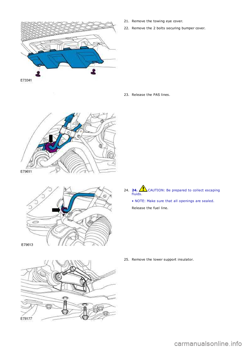
Remove t he towi ng eye cover.21.
Remove t he 2 bolt s s ecuring bumper cover.22.
Releas e t he PAS li nes .23.
24. CAUTION: Be prepared to col lect es capingfluids .
• NOTE: Make s ure that all openi ngs are s ealed.
Releas e t he fuel li ne.
24.
Remove t he lower s upport ins ul ator.25.