2006 LAND ROVER FRELANDER 2 suspension
[x] Cancel search: suspensionPage 270 of 3229
Publi s hed: 11-May-2011
Rear Suspension - Wheel Knuckle Rear Bushing
Removal and Inst all ati on
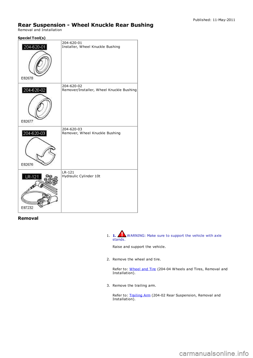
Special T ool(s)
204-620-01Inst all er, W heel Knuckle Bus hing
204-620-02Remover/Ins t al ler, W heel Knuckl e Bus hi ng
204-620-03Remover, W heel Knuckle Bushi ng
LR-121Hydrauli c Cyli nder 10t
Removal
1. W ARNING: Make sure t o s upport the vehicle wit h axles tands .
Rais e and s upport t he vehi cl e.
1.
Remove t he wheel and t ire.
Refer t o: W heel and Ti re (204-04 W heel s and Tires, Removal andInst all at ion).
2.
Remove t he trail ing arm.
Refer t o: Trail ing Arm (204-02 Rear Suspens ion, Removal andInst all at ion).
3.
Page 291 of 3229
Publi s hed: 11-May-2011
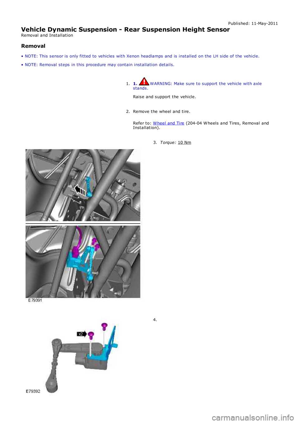
Vehicle Dynamic Suspension - Rear Suspension Height Sensor
Removal and Inst all ati on
Removal
• NOTE: This s ens or i s only fit ted to vehicles wit h Xenon headlamps and is i nst all ed on the LH s ide of t he vehi cl e.
• NOTE: Removal s t eps in t his procedure may cont ain i nst all ati on det ail s.
1. W ARNING: Make sure t o s upport the vehicle wit h axle
s tands .
Rais e and s upport t he vehi cl e.
1.
Remove t he wheel and t ire.
Refer t o: W heel and Ti re (204-04 W heel s and Tires, Removal and
Inst all at ion).
2. T orque:
10 Nm 3.
4.
Page 412 of 3229
1
1
1
1
2
3
4
5
6
7
1
1
Are the wheel bearings OK?YesGO to C6.NoINSTALL new wheel bearings as requi red.REFER to: Front W heel Beari ng (204-01 Front Sus pensi on, Removal and Ins t al lat ion).TEST t he sys t em for normal operat ion.
C6: CHECK SUSPENSION BUSHINGS AND BALL JOINT S
Check al l s us pensi on bushi ngs and bal l joint s.
Are the s us pens ion bus hings and ball joints OK?YesCheck and adjust s t eering geomet ryREFER to: Four-W heel Alignment (204-00 Suspens ion Sys tem - General Informati on, GeneralProcedures ).NoINSTALL new sus pens i on bus hings and ball joints as required. REFER t o t he rel evant sect ion i n t heworks hop manual.
PINPOINT TEST D : THE PEDAL FEELS SPONG Y
T ESTCONDIT IO NSDET AILS/RESULT S/ACT IO NS
D1: CHECK FOR SPONGY PEDAL (ENGINE OFF)
Check for a fi rm brake pedal.
Is t he brake pedal effort and brake pedal t ravel normal?YesVehi cl e i s OK.NoGO t o D2.
D2: CHECK BR AKE PEDAL RESERVE (ENGINE OFF)Pump t he brake pedal 10 t imes and hol d on t he final appli cat ion.
Does t he brake pedal feel fi rm on final appl icat ion?YesGO t o D3.NoBLEED the brake sys tem.REFER t o: Brake Sys tem Bleeding (206-00 Brake Sys tem - General Informat ion, GeneralProcedures ) /Brake Syst em Press ure Bleeding (206-00 Brake Sys tem - General Informat ion, General Procedures ).D3: CHECK BR AKE PEDAL RESERVE (ENGINE ON)
Appl y Parking Brake and ens ure transmis s ion i s in park/neutral .
Start engine and al low to idle.
Appl y t he brake pedal l ightl y t hree or four t imes .
W ait 15 seconds for t he vacuum t o recover.
Pus h down on the brake pedal unti l it s tops movi ng downward or an increas ed res i st ance to t hebrake pedal t ravel occurs .Hold t he brake pedal in t he applied pos it ion whi le increasi ng t he engi ne s peed t o 2000 rpm.
Rel ease the accel erat or pedal.
Does t he brake pedal move downward as t he engine s peed ret urns t o idl e?YesGO t o D4.NoCHECK the vacuum t o brake boos ter.
D4: CHECK BR AKE FLUID LEVELCheck t he brake mas t er cyli nder reservoi r fl ui d l evel.
Is t he fluid level OK?YesBLEED the brake sys tem.REFER t o: Brake Sys tem Bleeding (206-00 Brake Sys tem - General Informat ion, GeneralProcedures ) /Brake Syst em Press ure Bleeding (206-00 Brake Sys tem - General Informat ion, General Procedures ).TEST the s ys tem for normal operat ion.NoCHECK for l eaking brake s ys t em and RECTIFY as necess ary. ADD fl ui d and BLEED t he brakesys t em.REFER t o: Brake Sys tem Bleeding (206-00 Brake Sys tem - General Informat ion, GeneralProcedures ) /Brake Syst em Press ure Bleeding (206-00 Brake Sys tem - General Informat ion, General Procedures ).TEST the s ys tem for normal operat ion. REPEAT road tes t i f required.
PINPOINT TEST E : THE PEDAL GOES DOWN FAST
T ESTCONDIT IO NSDET AILS/RESULT S/ACT IONS
E1: ROAD T EST VEHICLE
Road t es t the vehicle and appl y the brake pedal .
Is t he brake pedal effort and brake pedal t ravel normal?YesVehi cl e is OK.NoGO t o E2.E2: PRESSURIZE SYST EM AND CHECK BRAKE PEDAL T RAVEL
Page 2546 of 3229
Publis hed: 11-May-2011
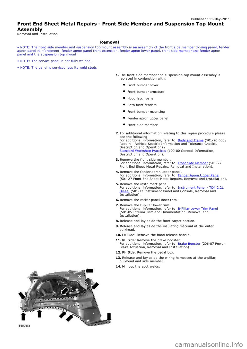
Front End Sheet Metal Repairs - Front Side Member and Suspension Top Mount
AssemblyRemoval and Ins tallat ion
Removal
• NO TE: The front s ide member and suspens ion t op mount as sembly is an ass embly of the front s ide member closing panel, fenderapron panel reinforcement, fender apron panel front ext ens ion, fender apron lower panel, front s ide member and fender apronpanel and the s uspens ion t op mount .
• NO TE: The service panel is not fully welded.
• NO TE: The panel is serviced les s it s weld s tuds
1. The front side member and suspens ion t op mount as sembly isreplaced in conjunct ion wit h:
Front bumper cover
Front bumper armat ure
Hood lat ch panel
Both front fenders
Front bumper mount ing
Fender apron upper panel
Front side member
2. For addit ional information relating t o t his repair procedure pleas es ee t he following:For addit ional informat ion, refer to: Body and Frame (501-26 BodyRepairs - Vehicle Specific Informat ion and Tolerance Checks ,Des cript ion and O perat ion) /Standard W orkshop Pract ices (100-00 General Informat ion,Des cript ion and O perat ion).
3. Remove t he front s ide member.For addit ional informat ion, refer to: Front Side Member (501-27Front End Sheet Met al Repairs, Removal and Ins t allat ion).
4. Remove t he fender apron upper panel.For addit ional informat ion, refer to: Fender Apron Upper Panel(501-27 Front End Sheet Met al Repairs, Removal and Ins t allat ion).
5. Remove t he ins t rument panel.For addit ional informat ion, refer to: Inst rument Panel - TD4 2.2LDiesel (501-12 Inst rument Panel and Cons ole, Removal andIns t allat ion).
6. Remove t he rocker panel inner t rim.
7. Remove t he B-pillar lower t rim.For addit ional informat ion, refer to: B-Pillar Lower Trim Panel(501-05 Int erior Trim and Ornamentat ion, Removal andIns t allat ion).
8. Releas e and lay as ide t he front carpet sect ion.
9. Releas e and lay as ide t he ins ulat ing mat erial at t he out erbulkhead.
10. LH Side: Remove the hood releas e handle.
11. RH Side: Remove the brake boost er.For addit ional informat ion, refer to: Brake Boost er (206-07 PowerBrake Act uat ion, Removal and Ins t allat ion).
12. RH Side: Remove the pedal box.
13. Release and lay aside t he wiring harnes ses at t he a-pillar,bulkhead and s ide member.
14. Mill out t he spot welds .
Page 2554 of 3229
Publi s hed: 11-May-2011
Front End Sheet Metal Repairs - Suspension Top Mount
Removal and Inst all ati on
Removal
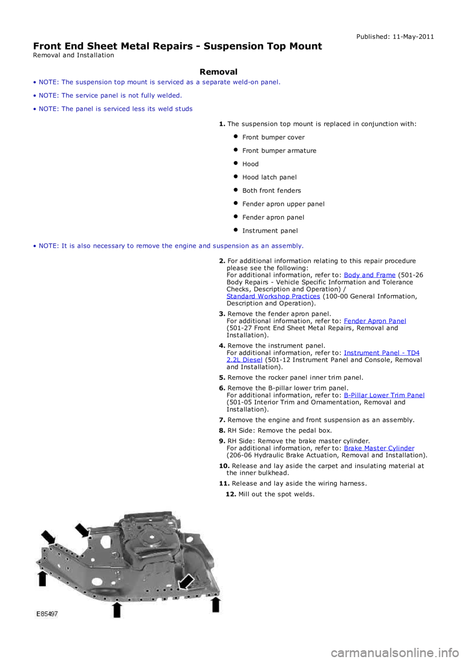
• NOTE: The s uspens ion t op mount is s ervi ced as a s eparate wel d-on panel.
• NOTE: The s ervice panel is not ful ly wel ded.
• NOTE: The panel i s s erviced les s i ts wel d s t uds
1. The sus pens i on top mount i s repl aced i n conjunct ion wi th:
Front bumper cover
Front bumper armature
Hood
Hood lat ch panel
Both front fenders
Fender apron upper panel
Fender apron panel
Ins t rument panel
• NOTE: It is al so neces sary t o remove t he engine and s us pens ion as an as s embly.
2. For addit ional informati on rel at ing to this repair procedurepleas e s ee t he foll owing:For addi ti onal informat ion, refer t o: Body and Frame (501-26Body Repai rs - Vehi cl e Speci fic Informat ion and ToleranceChecks , Descripti on and Operat ion) /Standard W orks hop Practi ces (100-00 General Informat ion,Des cript ion and Operat ion).
3. Remove the fender apron panel.For addi ti onal informat ion, refer t o: Fender Apron Panel(501-27 Front End Sheet Met al Repairs , Removal andIns t allat ion).
4. Remove the i nst rument panel.For addi ti onal informat ion, refer t o: Ins t rument Panel - TD42.2L Di esel (501-12 Ins t rument Panel and Cons ole, Removaland Ins t allat ion).
5. Remove the rocker panel i nner t ri m panel.
6. Remove the B-pill ar lower trim panel .For addi ti onal informat ion, refer t o: B-Pi ll ar Lower Tri m Panel(501-05 Int eri or Trim and Ornament ati on, Removal andIns t allat ion).
7. Remove the engine and front s uspens ion as an as s embly.
8. RH Side: Remove t he pedal box.
9. RH Side: Remove t he brake mas ter cylinder.For addi ti onal informat ion, refer t o: Brake Mas t er Cyli nder(206-06 Hydraulic Brake Actuati on, Removal and Ins t al lat ion).
10. Rel eas e and l ay as ide t he carpet and ins ul ati ng mat erial att he inner bul khead.
11. Rel eas e and l ay as ide t he wiring harnes s .
12. Mil l out t he s pot wel ds.
Page 2557 of 3229
Publ is hed: 11-May-2011
Front End Sheet Metal Repairs - Front Side Member Section
Removal and Installation
Removal
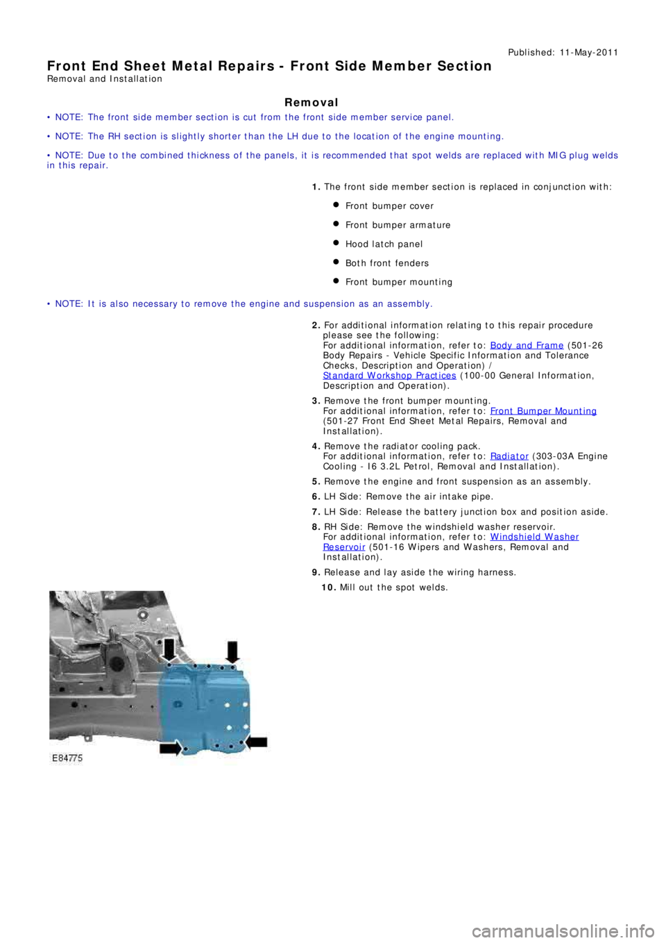
• NOTE: The front side member section is cut from the front side member service panel.
• NOTE: The RH section is slightly shorter than the LH due to the location of the engine mounting.
• NOTE: Due to the combined thickness of the panels, it is recommended that spot welds are replaced with MIG plug welds
in this repair.
1. The front s ide member s ect ion is replaced in conjunct ion wit h:
Front bumper cover
Front bumpe r a rma t ure
Hood lat ch panel
Both front fenders
Front bumpe r mount i ng
• NOTE: It is also necessary to remove the engine and suspension as an assembly.
2. Fo r a d d i t i o na l i nf o rma t i o n re l a t i ng t o t hi s re p a i r p ro ce d ure
please see the following:
Fo r a d d i t i o na l i nf o rma t i o n, re f e r t o : Body and Frame
(501-26
Body Repairs - Vehicle Specific Information and Tolerance
Checks, Description and Operation) /
St a nd a rd W o rks ho p P ra ct i ce s
(100-00 Ge ne ra l I nf o rma t i o n,
Description and Operation).
3. Re move t he f ront bumpe r mount i ng.
Fo r a d d i t i o na l i nf o rma t i o n, re f e r t o : Front Bumper Mount ing
(501-27 Front End Sheet Met al Re pai rs , Removal and
Installation).
4. Remove the radiator cooling pack.
Fo r a d d i t i o na l i nf o rma t i o n, re f e r t o : Radiator
(303-03A Engi ne
Cooling - I6 3.2L Petrol, Removal and Installation).
5. Remove the engine and front suspension as an assembly.
6. LH Side: Remove the air intake pipe.
7. LH Side: Release the battery junction box and position aside.
8. RH Side: Remove the windshield washer reservoir.
Fo r a d d i t i o na l i nf o rma t i o n, re f e r t o : Windshield Washer
Res ervoi r (501-16 W i pers and W as hers , Removal and
Installation).
9. Release and lay aside the wiring harness.
10. Mill out the spot welds.
Page 2564 of 3229
Publ is hed: 11-May-2011
Front End Sheet Metal Repairs - Fender Apron Panel Reinforcement
Removal and Installation
Removal
• NOTE: The fender apron panel reinforcement has to be unpicked from the fender apron panel service panel, it is not
available separately.
• NOTE: The RH panel is serviced less its weld studs 1. T he f e nd e r a p ro n p a ne l re i nf o rce me nt i s re p l a ce d i n
conjunct ion wit h:
Front bumper cover
Hood lat ch panel
Both front fenders
Fender apron upper panel
2. Fo r a d d i t i o na l i nf o rma t i o n re l a t i ng t o t hi s re p a i r p ro ce d ure
please see the following:
Fo r a d d i t i o na l i nf o rma t i o n, re f e r t o : Body and Frame
(501-26
Body Repairs - Vehicle Specific Information and Tolerance
Checks, Description and Operation) /
St a nd a rd W o rks ho p P ra ct i ce s
(100-00 Ge ne ra l I nf o rma t i o n,
Description and Operation).
3. Remove the fender apron upper panel.
Fo r a d d i t i o na l i nf o rma t i o n, re f e r t o : Fender Apron Upper Panel
(501-27 Front End Sheet Met al Re pai rs , Removal and
Installation).
4. Remove the front shock absorber.
Fo r a d d i t i o na l i nf o rma t i o n, re f e r t o : Front Shock Abs orber
(204-01 Front Suspension, Removal and Installation).
5. LH Side: Remove the engine support insulator.
Fo r a d d i t i o na l i nf o rma t i o n, re f e r t o : Engine Upper Support
Insulator (303-01B Engi ne - TD4 2.2L Di es el, Removal and
Installation).
6. LH Side: Remove the bat tery t ray.
Fo r a d d i t i o na l i nf o rma t i o n, re f e r t o : Battery Tray
(414-01
Battery, Mounting and Cables, Removal and Installation).
7. LH Side: Remove the air intake pipe.
8. LH Side: Release the battery junction box and position aside.
9. RH Side: Remove the windshield washer reservoir.
Fo r a d d i t i o na l i nf o rma t i o n, re f e r t o : Windshield Washer
Res ervoi r (501-16 W i pers and W as hers , Removal and
Installation).
10. RH Side: Remove the engine mounting bracket.
Fo r a d d i t i o na l i nf o rma t i o n, re f e r t o : Engine Mount RH
(303-01B
Engine - TD4 2.2L Diesel, Removal and Installation).
11. RH Side: Release the coolant expansion tank and lay it
aside.
12. RH Side: Evacuate the A/C system.
Fo r a d d i t i o na l i nf o rma t i o n, re f e r t o : Air Conditioning (A/C)
System Recovery, Evacuation and Charging (412-00 Cl i mat e
Co nt ro l Sys t e m - Ge ne ra l I nf o rma t i o n, Ge ne ra l P ro ce d ure s ).
13. RH Side: Remove the fender apron A/C pipes.
14. RH Side: Release and lay aside the insulating material at the
bulkhead.
15. Release and lay aside the wiring harness.
Page 2574 of 3229
Publ is hed: 11-May-2011
Front End Sheet Metal Repairs - Front Side Member Closing Panel
Removal and Installation
Removal
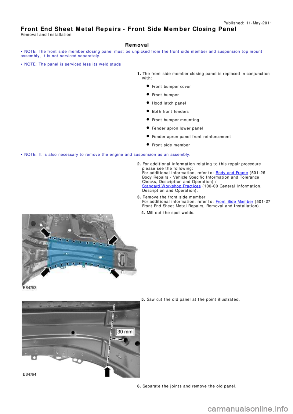
• NOTE: The front side member closing panel must be unpicked from the front side member and suspension top mount
assembly, it is not serviced separately.
• NOTE: The panel is serviced less its weld studs
1. The front side member closing panel is replaced in conjunction
with:
Front bumper cover
Front bumper
Hood lat ch panel
Both front fenders
Front bumpe r mount i ng
Fender apron l ower panel
Fender apron panel front reinforcement
Front s i de me mbe r
• NOTE: It is also necessary to remove the engine and suspension as an assembly.
2. Fo r a d d i t i o na l i nf o rma t i o n re l a t i ng t o t hi s re p a i r p ro ce d ure
please see the following:
Fo r a d d i t i o na l i nf o rma t i o n, re f e r t o : Body and Frame
(501-26
Body Repairs - Vehicle Specific Information and Tolerance
Checks, Description and Operation) /
St a nd a rd W o rks ho p P ra ct i ce s
(100-00 Ge ne ra l I nf o rma t i o n,
Description and Operation).
3. Re move t he f ront s i de me mbe r.
Fo r a d d i t i o na l i nf o rma t i o n, re f e r t o : Front Side Member
(501-27
Front End Sheet Metal Repairs, Removal and Installation).
4. Mill out the spot welds.
5. Saw cut the old panel at the point illustrated.
6. Separate the joints and remove the old panel.