2006 LAND ROVER FRELANDER 2 clutch
[x] Cancel search: clutchPage 1286 of 3229
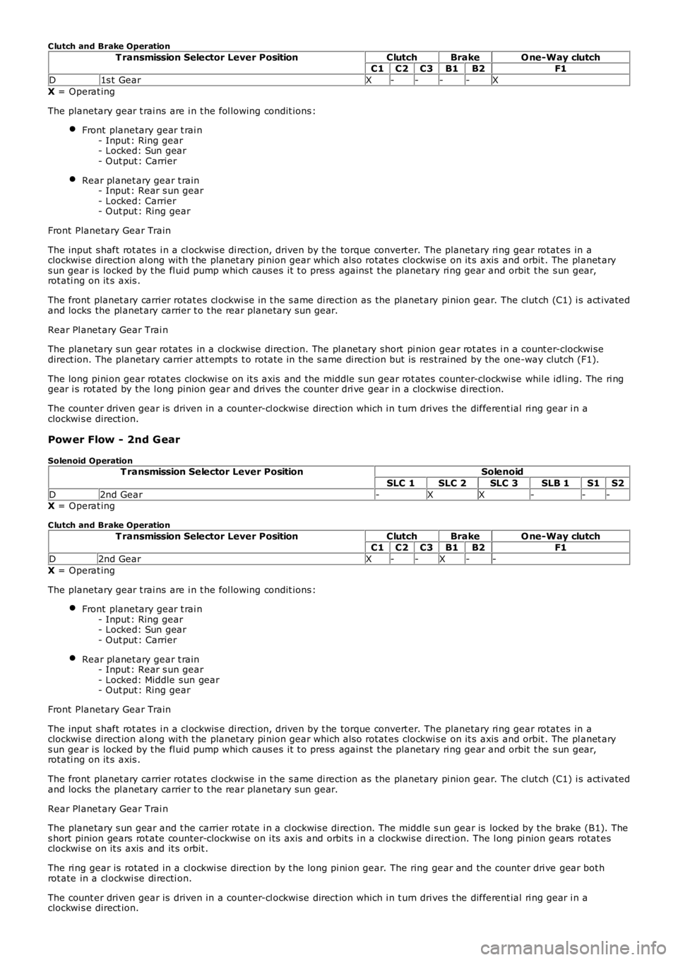
C lutch and Brake Operation
T ransmission Selector Lever PositionClutchBrakeO ne-Way clutchC1C2C3B1B2F1
D1s t GearX----X
X = Operat ing
The planetary gear t rai ns are i n t he fol lowing condit ions :
Front planetary gear t rai n- Input : Ring gear- Locked: Sun gear- Out put : Carrier
Rear pl anet ary gear t rain- Input : Rear s un gear- Locked: Carrier- Out put : Ring gear
Front Planetary Gear Train
The input s haft rot ates i n a cl ockwis e di recti on, driven by t he torque convert er. The planetary ri ng gear rotat es in aclockwi s e direct ion al ong wit h t he planet ary pi nion gear which als o rotat es clockwi se on it s axis and orbit . The pl anet arys un gear i s locked by t he fl ui d pump whi ch caus es it t o press agains t t he planetary ri ng gear and orbit t he s un gear,rot ati ng on it s axis .
The front planet ary carri er rotat es cl ockwi se in t he s ame di recti on as the pl anet ary pi nion gear. The clut ch (C1) i s act ivatedand locks the pl anet ary carrier t o t he rear planetary s un gear.
Rear Pl anet ary Gear Trai n
The planetary s un gear rotat es in a cl ockwi se direct ion. The pl anet ary short pi nion gear rot at es i n a count er-clockwi sedirect ion. The planetary carri er at t empt s t o rotat e in the s ame di recti on but is rest rai ned by the one-way clutch (F1).
The long pi ni on gear rotat es clockwi s e on it s axis and the middle s un gear rot ates count er-clockwi se whil e idl ing. The ri nggear i s rot ated by the l ong pinion gear and dri ves the counter dri ve gear i n a clockwis e di recti on.
The count er driven gear is driven in a count er-cl ockwi se direct ion which i n t urn drives t he different ial ri ng gear i n aclockwi s e direct ion.
Power Flow - 2nd G ear
Solenoid OperationT ransmission Selector Lever PositionSolenoid
SLC 1SLC 2SLC 3SLB 1S1S2
D2nd Gear-XX---X = Operat ing
C lutch and Brake Operation
T ransmission Selector Lever PositionClutchBrakeO ne-Way clutchC1C2C3B1B2F1
D2nd GearX--X--
X = Operat ing
The planetary gear t rai ns are i n t he fol lowing condit ions :
Front planetary gear t rai n- Input : Ring gear- Locked: Sun gear- Out put : Carrier
Rear pl anet ary gear t rain- Input : Rear s un gear- Locked: Middle sun gear- Out put : Ring gear
Front Planetary Gear Train
The input s haft rot ates i n a cl ockwis e di recti on, driven by t he torque convert er. The planetary ri ng gear rotat es in aclockwi s e direct ion al ong wit h t he planet ary pi nion gear which als o rotat es clockwi se on it s axis and orbit . The pl anet arys un gear i s locked by t he fl ui d pump whi ch caus es it t o press agains t t he planetary ri ng gear and orbit t he s un gear,rot ati ng on it s axis .
The front planet ary carri er rotat es cl ockwi se in t he s ame di recti on as the pl anet ary pi nion gear. The clut ch (C1) i s act ivatedand locks the pl anet ary carrier t o t he rear planetary s un gear.
Rear Pl anet ary Gear Trai n
The planetary s un gear and t he carrier rot ate i n a cl ockwis e di recti on. The middle sun gear is locked by t he brake (B1). Thes hort pinion gears rot ate counter-clockwis e on i ts axi s and orbit s i n a clockwis e direct ion. The l ong pi nion gears rotat esclockwi s e on it s axis and it s orbit .
The ri ng gear is rotat ed in a cl ockwi se direct ion by t he long pi ni on gear. The ring gear and the counter dri ve gear bot hrot ate in a cl ockwi se di recti on.
The count er driven gear is driven in a count er-cl ockwi se direct ion which i n t urn drives t he different ial ri ng gear i n aclockwi s e direct ion.
Page 1287 of 3229

• NOTE: Engine braking is avail abl e when t hi s gear is s elected.
Power Flow - 3rd Gear
Solenoid Operation
T ransmission Selector Lever PositionSolenoid
SLC 1SLC 2SLC 3SLB 1S1S2D3rd Gear-X-X--
X = Operat ing
C lutch and Brake OperationT ransmission Selector Lever PositionClutchBrakeO ne-Way clutch
C1C2C3B1B2F1
D3rd GearX--X--X = Operat ing
The planetary gear t rai ns are i n t he fol lowing condit ions :
Front planetary gear t rai n- Input : Ring gear- Locked: Sun gear- Out put : Carrier
Rear pl anet ary gear t rain- Input : Middle sun gear- Locked: -- Out put : Ring gear
Front Planetary Gear Train
The input s haft rot ates i n a cl ockwis e di recti on, driven by t he torque convert er. The planetary ri ng gear rotat es in aclockwi s e direct ion al ong wit h t he planet ary pi nion gear which als o rotat es clockwi se on it s axis and orbit . The pl anet arys un gear i s locked by t he fl ui d pump whi ch caus es it t o press agains t t he planetary ri ng gear and orbit t he s un gear,rot ati ng on it s axis .
The front planet ary carri er rotat es cl ockwi se in t he s ame di recti on as the pl anet ary pi nion gear. The clut ch (C1) i s act ivatedand locks the pl anet ary carrier t o t he rear planetary s un gear. Clut ch (C3) i s als o acti vat ed and locks the carri er t o t hemi ddl e s un gear.
Rear Pl anet ary Gear Trai n
The planetary s hort pinion gear and t he long pini on gear are engaged whi ch caus es both pi nion gears t o l ock due t o t hedifferent rotat ional di recti ons . Torque from the sun gear and mi ddl e s un gear is t rans mit t ed to the pl anet ary ring gearwhich rotat es cl ockwi se in t he s ame di recti on as the pl anet ary carrier.
The count er drive gear rot ates i n a clockwis e di recti on wit h t he ri ng gear.
The count er driven gear is rotat ed in a count er-cl ockwis e di recti on which i n t urn drives the di fferenti al ri ng gear i n aclockwi s e direct ion.
• NOTE: Engine braking is avail abl e when t hi s gear is s elected.
Power Flow - 4th Gear
Solenoid OperationT ransmission Selector Lever PositionSolenoid
SLC 1SLC 2SLC 3SLB 1S1S2
D4t h Gear--XX--X = Operat ing
C lutch and Brake Operation
T ransmission Selector Lever PositionClutchBrakeO ne-Way clutchC1C2C3B1B2F1
D4t h GearXX----
X = Operat ing
The planetary gear t rai ns are i n t he fol lowing condit ions :
Front planetary gear t rai n- Input : Ring gear- Locked: Sun gear- Out put : Carrier
Rear pl anet ary gear t rain- Input : Rear s un gear, Carrier- Locked: -- Out put : Ring gear
Front Planetary Gear Train
The input s haft rot ates i n a cl ockwis e di recti on, driven by t he torque convert er. The planetary ri ng gear rotat es in aclockwi s e direct ion al ong wit h t he planet ary pi nion gear which als o rotat es clockwi se on it s axis and orbit . The pl anet arys un gear i s locked by t he fl ui d pump whi ch caus es it t o press agains t t he planetary ri ng gear and orbit t he s un gear,rot ati ng on it s axis .
Page 1288 of 3229

The front planet ary carri er rotat es cl ockwi se in t he s ame di recti on as the pl anet ary pi nion gear. The clut ch (C1) i s act ivatedand locks the pl anet ary carrier t o t he rear planetary s un gear. The int ermediat e s haft rotat es in t he s ame di recti on as theinput s haft. Cl utch (C2) is al so act ivated rotat es in the s ame di recti on as t he int ermediat e s haft .
Rear Pl anet ary Gear Trai n
The planetary carri er rot at es in a clockwis e direct ion wit h the intermediat e s haft. The s hort pi ni on gear rotat es clockwi s eon i ts axis and orbit s at a fast er s peed t han t he sun gear. The long pini on gear rotat es counter-clockwis e on i ts axi s andorbi t. The rot ati on of the ri ng gear i s in a clockwi s e direct ion and i s s lower than t he rotat ion of t he carri er due t o t he l ongpinion gear's rotat ion i s count eract ed by t he planetary carri er.
The count er drive gear rot ates i n a clockwis e di recti on wit h t he ri ng gear.
The count er driven gear is rotat ed in a count er-cl ockwis e di recti on which i n t urn drives the di fferenti al ri ng gear i n aclockwi s e direct ion.
• NOTE: Engine braking is avail abl e when t hi s gear is s elected.
Power Flow - 5th Gear
Solenoid Operation
T ransmission Selector Lever PositionSolenoid
SLC 1SLC 2SLC 3SLB 1S1S2D5t h GearX--X--
X = Operat ing
C lutch and Brake Operation
T ransmission Selector Lever PositionClutchBrakeO ne-Way clutchC1C2C3B1B2F1
D5t h Gear-XX---
X = Operat ing
The planetary gear t rai ns are i n t he fol lowing condit ions :
Front planetary gear t rai n- Input : Ring gear- Locked: Sun gear- Out put : Carrier
Rear pl anet ary gear t rain- Input : Middle sun gear- Locked: -- Out put : Ring gear
Front Planetary Gear Train
The input s haft rot ates i n a cl ockwis e di recti on, driven by t he torque convert er. The planetary ri ng gear rotat es in aclockwi s e direct ion al ong wit h t he planet ary pi nion gear which als o rotat es clockwi se on it s axis and orbit . The pl anet arys un gear i s locked by t he fl ui d pump whi ch caus es it t o press agains t t he planetary ri ng gear and orbit t he s un gear,rot ati ng on it s axis .
The front planet ary carri er rotat es cl ockwi se in t he s ame di recti on as the pl anet ary pi nion gear. The clut ch (C3) i s act ivatedand locks the pl anet ary carrier t o t he rear planetary mi ddl e s un gear. The int ermediat e s haft rotat es in t he s ame di recti onas t he input s haft. Cl ut ch (C2) i s als o act ivated and rotat es in t he s ame di recti on as the intermediat e s haft.
Rear Pl anet ary Gear Trai n
The mi ddl e s un gear rotat es clockwi se in the s ame di recti on as clutch (C3). The decelerat ion of t he front pl anet ary gears lows t he s peed of t he i nput s haft . The int ermediat e s haft rot ates clockwis e i n t he s ame direct ion as t he i nput s haft . Theplanetary carri er al s o rot ates clockwis e i n t he s ame direct ion as t he i nt ermedi ate shaft .
The long pi ni on gear rotat es clockwi s e on it s axis and orbit . The carri er rotat es fas t er t han t he middle s un gear whi chcaus es t he mi ddl e pinion gear t o be cancell ed out by the speed difference. The mi ddle pini on gear orbi ts and rot at es on i tsaxis i n a clockwis e direct ion.
The planetary ri ng gear rotat es in a clockwi s e direct ion. The s peed of t he ri ng gear is fast er than t he planetary carri erbecaus e t he long pini on gear's rotat ion i s combined wi th t he planet ary carrier's s peed. The count er drive gear rot ates i n aclockwi s e direct ion wi th the ring gear.
The count er driven gear is rotat ed in a count er-cl ockwis e di recti on which i n t urn drives the di fferenti al ri ng gear i n aclockwi s e direct ion.
• NOTE: Engine braking is avail abl e when t hi s gear is s elected.
Power Flow - 6th Gear
Solenoid OperationT ransmission Selector Lever PositionSolenoid
SLC 1SLC 2SLC 3SLB 1S1S2
D6t h GearX-X---X = Operat ing
C lutch and Brake Operation
T ransmission Selector Lever PositionClutchBrakeO ne-Way clutchC1C2C3B1B2F1
Page 1289 of 3229
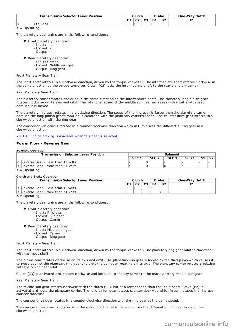
T ransmission Selector Lever PositionClutchBrakeO ne-Way clutch
C1C2C3B1B2F1
D6t h Gear-X-X--X = Operat ing
The planetary gear t rai ns are i n t he fol lowing condit ions :
Front planetary gear t rai n- Input : -- Locked: -- Out put : -
Rear pl anet ary gear t rain- Input : Carrier- Locked: Middle sun gear- Out put : Ring gear
Front Planetary Gear Train
The input s haft rot ates i n a cl ockwis e di recti on, driven by t he torque convert er. The int ermedi at e s haft rotat es cl ockwi se int he same direct ion as t he t orque convert er. Cl utch (C2) locks t he i nt ermedi ate s haft t o t he rear pl anet ary carrier.
Rear Pl anet ary Gear Trai n
The planetary carri er rot at es clockwi s e in the s ame di recti on as t he int ermediat e s haft . The pl anet ary long pinion gearrot ates clockwis e on i ts axi s and orbi t. The rot ati onal s peed of the middle sun gear increas es wit h i nput s haft s peedbecaus e it is l ocked.
The planetary ri ng gear rotat es in a clockwi s e direct ion. The s peed of t he ri ng gear is fast er than t he planetary carri erbecaus e t he long pini on gear's rotat ion i s combined wi th t he planet ary carrier's s peed. The count er drive gear rot ates i n aclockwi s e direct ion wi th the ring gear.
The count er driven gear is rotat ed in a count er-cl ockwis e di recti on which i n t urn drives the di fferenti al ri ng gear i n aclockwi s e direct ion.
• NOTE: Engine braking is avail abl e when t hi s gear is s elected.
Power Flow - Reverse Gear
Solenoid OperationT ransmission Selector Lever PositionSolenoid
SLC 1SLC 2SLC 3SLB 1S1S2
RRevers e Gear - Less than 11 volt sXX-X--RRevers e Gear - More than 11 vol tsXXXX--
X = Operat ing
C lutch and Brake Operation
T ransmission Selector Lever PositionClutchBrakeO ne-Way clutchC1C2C3B1B2F1
RReverse Gear - Les s t han 11 vol ts-X-X--
RReverse Gear - More t han 11 volt s----X-X = Operat ing
The planetary gear t rai ns are i n t he fol lowing condit ions :
Front planetary gear t rai n- Input : Ring gear- Locked: Sun gear- Out put : Carrier
Rear pl anet ary gear t rain- Input : Middle sun gear- Locked: Carrier- Out put : Ring gear
Front Planetary Gear Train
The input s haft rot ates i n a cl ockwis e di recti on, driven by t he torque convert er. The planetary ri ng gear rotat es clockwi s ewit h t he i nput s haft .
The pinion gear rot ates cl ockwis e on it s axi s and orbi t. The pl anet ary s un gear is locked by t he fl uid pump which caus es i tt o pres s agains t the pl anet ary ring gear and orbit the s un gear, rotat ing on i ts axis. The pl anet ary carrier rot ates clockwis ewit h t he pini on gear orbi t.
Clut ch (C3) i s act ivated and rot at es clockwi s e and locks the pl anet ary carrier t o t he rear planetary mi ddl e s un gear.
Rear Pl anet ary Gear Trai n
The mi ddl e s un gear rotat es clockwi se wit h t he clutch (C3), but at a l ower speed t han the i nput s haft . Brake (B2) isact ivat ed and locks the pl anet ary carrier. The long pini on gear rotat es counter-clockwis e whi ch in t urn rotat es t he ri ng gearcount er-cl ockwis e.
The count er drive gear rot ates i n a counter-clockwi s e direct ion wi th the ring gear at t he s ame s peed.
The count er driven gear is rotat ed in a clockwi s e direct ion whi ch in t urn drives t he different ial ri ng gear in a counter-clockwi s e direct ion.
Page 1290 of 3229
• NOTE: Engine braking is avail abl e when t hi s gear is s elected.
Power Flow Neutral
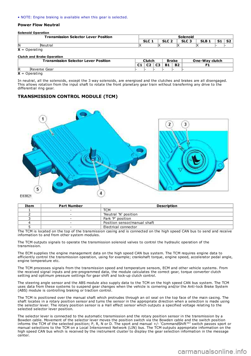
Solenoid Operation
T ransmission Selector Lever PositionSolenoid
SLC 1SLC 2SLC 3SLB 1S1S2NNeutralXXXX--
X = Operat ing
C lutch and Brake OperationT ransmission Selector Lever PositionClutchBrakeO ne-Way clutch
C1C2C3B1B2F1
RRevers e Gear------X = Operat ing
In neut ral , all the sol enoi ds , except t he 3 way s olenoids , are energi s ed and the cl ut ches and brakes are all di sengaged.This al lows rot ati on from the i nput s haft t o rotat e t he front pl anet ary gear train wit hout t rans ferring any drive t o t hedifferent ial ri ng gear.
TRANSMISSION CONTROL MODULE (TCM)
ItemPart NumberDescription1-TCM
2-'Neutral 'N' pos it ion
3-Park 'P' posi ti on4-Pos it ion sens or/manual s haft
5-El ect ri cal connector
The TCM i s located on the t op of t he trans mi s si on cas i ng and is connect ed on t he high s peed CAN bus t o s end and receiveinformat ion t o and from other s ys t em modules .
The TCM out put s s ignals t o operat e t he transmis si on s olenoid valves t o cont rol t he hydraulic operat ion of t het ransmis s ion.
The ECM s upplies t he engine management dat a on t he high speed CAN bus s ys tem. The TCM requires engi ne dat a t oefficient ly control t he t rans mis s ion operat ion, usi ng for example; cranks haft torque, engine s peed, accel erat or pedal angl e,engi ne t emperature etc.
The TCM proces ses si gnal s from t he t rans mis s ion s peed and t emperature s ens ors , ECM and ot her vehicl e s ys t ems . Fromt he received s ignal i nput s and pre-programmed data, t he module calculat es the correct gear, t orque converter clut chs ett ing and opt imum pres sure s ett ings for gear s hift and lock-up clut ch control.
The s teeri ng angle s ensor and t he ABS module als o s uppl y data to t he TCM on the hi gh s peed CAN bus sys t em. The TCMus es dat a from thes e s yst ems t o s us pend gear changes when t he vehi cl e is cornering and/or t he Anti -l ock Brake Syst em(ABS) module is controll ing braking or t ract ion control .
The TCM i s posi ti oned over t he manual s haft whi ch protrudes through an oi l seal on the t op face of the main cas ing. Thes haft locates i n a rotary posi ti on s ens or and t urns t he sens or in t he appropri ate directi on when a s electi on is made us ingt he sel ect or lever. The rot ary pos it ion s ens or i s a Hal l effect s ens or which out put s a s pecifi ed volt age relat ing t o t hes elect ed s elector l ever posi ti on.
The s elect or lever is connect ed to the aut omati c transmis si on and t he rot ary pos it ion s ensor i n t he transmis si on by aBowden cabl e. Movement of the s elect or l ever moves t he posi ti on s wit ch vi a t he Bowden cabl e and the swi tch pos it ioninforms the TCM of t he s elected pos it ion; P, R, N or D. The s port and manual +/- 'CommandShi ft ™' s wit ch pas s es s port ormanual s elect ions to the TCM on a Local Interconnect Net work (LIN) bus . The TCM out put s appropri at e i nformati on on thehigh s peed CAN bus whi ch is received by t he i ns t rument clus ter t o dis play t he gear sel ect ion i nformati on in t he mes s agecent er.
Page 1390 of 3229
Publi s hed: 11-May-2011
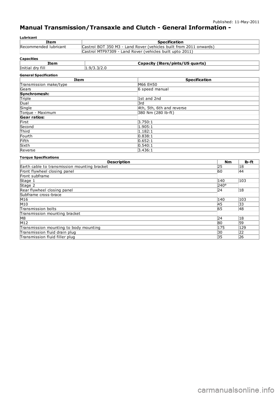
Manual Transmission/Transaxle and Clutch - General Information -
LubricantItemSpecification
Recommended lubri cantCas trol BOT 350 M3 - Land Rover (vehicles buil t from 2011 onwards )
Cas trol MTF97309 - Land Rover (vehi cl es bui lt upt o 2011)
C apacities
ItemCapacity (liters/pints/US quarts)Init ial dry fil l1.9/3.3/2.0
General Specification
ItemSpecification
Trans mi ss ion make/typeM66 EH50Gears6 s peed manual
Synchromesh:
Tri ple1s t and 2ndDual3rd
Single4t h, 5th, 6t h and revers e
Torque - Maximum380 Nm (280 lb-ft )Gear ratios:
Firs t3.750:1
Second1.905:1Third1.182:1
Fourt h0.838:1
Fifth0.652:1Sixt h0.540:1
Revers e3.436:1
Torque Specifications
DescriptionNmlb-ftEart h cable t o t rans mis s ion mount ing bracket2518
Front flywheel clos ing panel6044
Front s ubframeSt age 1140103
St age 2240°
Rear fl ywheel clos ing panel2418Subframe cros s -brace
M16140103
M104533Trans mi ss ion bol ts6548
Trans mi ss ion mount ing bracket
M82418M128059
Trans mi ss ion mount ing to body mount ing175129
Trans mi ss ion fl ui d drai n plug3022Trans mi ss ion fl ui d fill er plug3526
Page 1391 of 3229
Publi s hed: 11-May-2011
Manual Transmission/Transaxle and Clutch - General Information - Manual
Transmission and Clutch
Des cript ion and Operat ion
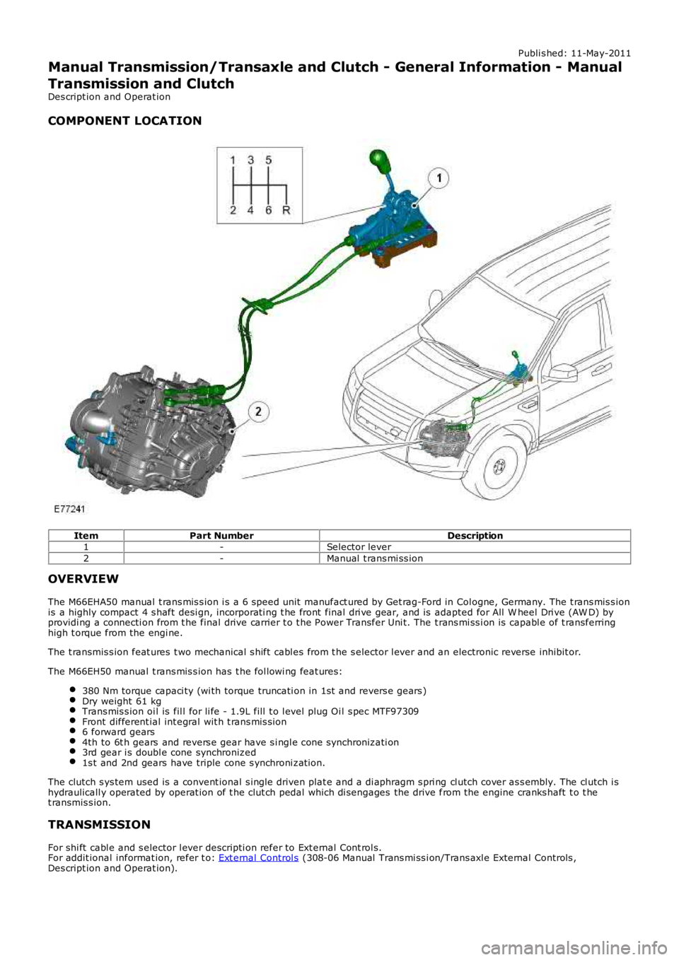
COMPONENT LOCATION
ItemPart NumberDescription1-Selector lever
2-Manual t rans mi ss ion
OVERVIEW
The M66EHA50 manual t rans mis s ion i s a 6 speed unit manufact ured by Get rag-Ford in Col ogne, Germany. The t rans mis s ionis a highly compact 4 s haft desi gn, incorporati ng t he front final dri ve gear, and is adapted for All W heel Dri ve (AW D) byprovidi ng a connecti on from t he final drive carrier t o t he Power Transfer Uni t. The t rans mi ss i on is capabl e of t ransferringhigh t orque from the engi ne.
The t ransmis s ion feat ures t wo mechanical s hift cabl es from t he s elector l ever and an electronic reverse inhibit or.
The M66EH50 manual t rans mis s ion has t he fol lowi ng feat ures:
380 Nm torque capaci ty (wi th torque truncati on in 1st and revers e gears )Dry weight 61 kgTrans mis s ion oi l is fil l for li fe - 1.9L fill t o l evel plug Oi l s pec MTF97309Front different ial int egral wit h t rans mis s ion6 forward gears4th to 6t h gears and revers e gear have s i ngl e cone synchronizati on3rd gear i s doubl e cone synchronized1s t and 2nd gears have triple cone s ynchroni zat ion.
The clutch s ys tem used is a convent ional s ingle driven plat e and a di aphragm s pri ng cl utch cover as s embly. The cl utch i shydraulicall y operated by operat ion of t he clut ch pedal which di sengages the drive from the engine cranks haft t o t het ransmis s ion.
TRANSMISSION
For shi ft cabl e and s elector l ever descripti on refer to Ext ernal Cont rol s.For addit ional informat ion, refer t o: Ext ernal Control s (308-06 Manual Trans mi ss i on/Trans axl e External Controls ,Des cript ion and Operat ion).
Page 1400 of 3229
s ynchronizi ng hub towards the revers e gear i dler gear.
The coupl ing s leeve and s ynchronizi ng hub lock t he revers e gear idler gear at the revers e s haft.
The t orque of the engine is t rans ferred via the cl ut ch t o the input shaft. The 1s t gear on t he i nput s haft t rans fers power t ot he 1st gear idl er gear. The power is then t rans ferred t o t he revers e gear idl er gear and then t o t he reverse gear coupl ings leeve. From t here power is trans ferred to t he i nt ermedi ate s haft 1s t - 2nd and 5t h - 6th and to the final dri ve which i nt urn t rans fers power t o t he ring gear. The ring gear is connect ed to the drive s hafts t hrough the di fferenti al.
Differential
The different ial dis t ribut es dri ve from t he t ransmis s ion equally bet ween t he LH and RH front half s haft s and als o provi desdri ve torque to the rear di fferenti al vi a t he power t rans fer unit .
The different ial is locat ed at t he rear of the trans mi ss i on hous ing. Both s ides of the di fferenti al are connected to t he LHand RH drive s haft s, s upplying t orque t o t he front wheel s The different ial is als o connected t o t he Power Transfer Unit viaa s pli ned shaft to the RH s ide of t he trans mi s si on, s upplying t orque t o t he rear driveline.
Reverse Switch
The revers e s wi tch i s located i n t he front of the t rans mis s ion cas ing, above t he 1s t gear det ect ion s wi tch. The swi tch i sus ed by the Ant i-lock Brake Sys tem (ABS) module for Hil l Descent Cont rol (HDC) and als o for revers ing l amp operati on.
1st Gear Position Switch
The 1s t gear s wit ch is locat ed on t he front of the t rans mi ss ion cas ing, below t he reverse swit ch. The s wit ch is us ed by t heABS module for HDC.
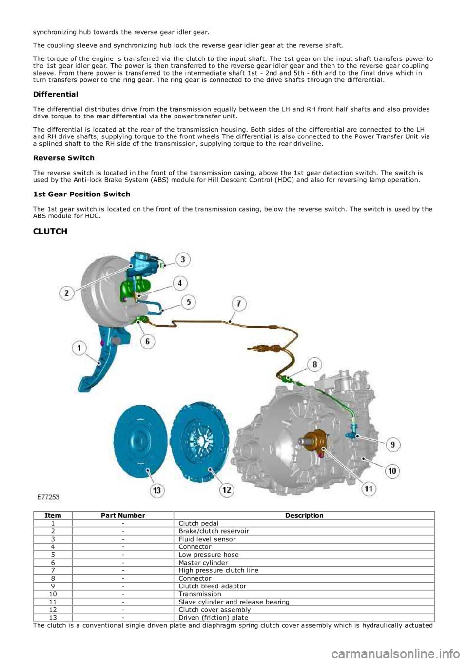
CLUTCH
ItemPart NumberDescription1-Clutch pedal
2-Brake/clut ch res ervoir
3-Fl uid l evel s ensor4-Connector
5-Low pres s ure hos e
6-Mast er cyl inder7-High pres s ure cl utch l ine
8-Connector
9-Clutch bl eed adapt or10-Transmis s ion
11-Slave cyl inder and releas e beari ng
12-Clutch cover as s embly13-Dri ven (fri ct ion) plat e
The clutch i s a convent ional si ngl e driven plat e and diaphragm spring clut ch cover ass embly which is hydraul ically act uat ed