2006 LAND ROVER FRELANDER 2 transmission
[x] Cancel search: transmissionPage 1290 of 3229
• NOTE: Engine braking is avail abl e when t hi s gear is s elected.
Power Flow Neutral
Solenoid Operation
T ransmission Selector Lever PositionSolenoid
SLC 1SLC 2SLC 3SLB 1S1S2NNeutralXXXX--
X = Operat ing
C lutch and Brake OperationT ransmission Selector Lever PositionClutchBrakeO ne-Way clutch
C1C2C3B1B2F1
RRevers e Gear------X = Operat ing
In neut ral , all the sol enoi ds , except t he 3 way s olenoids , are energi s ed and the cl ut ches and brakes are all di sengaged.This al lows rot ati on from the i nput s haft t o rotat e t he front pl anet ary gear train wit hout t rans ferring any drive t o t hedifferent ial ri ng gear.
TRANSMISSION CONTROL MODULE (TCM)
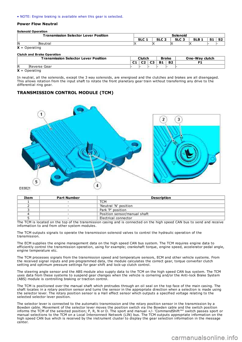
ItemPart NumberDescription1-TCM
2-'Neutral 'N' pos it ion
3-Park 'P' posi ti on4-Pos it ion sens or/manual s haft
5-El ect ri cal connector
The TCM i s located on the t op of t he trans mi s si on cas i ng and is connect ed on t he high s peed CAN bus t o s end and receiveinformat ion t o and from other s ys t em modules .
The TCM out put s s ignals t o operat e t he transmis si on s olenoid valves t o cont rol t he hydraulic operat ion of t het ransmis s ion.
The ECM s upplies t he engine management dat a on t he high speed CAN bus s ys tem. The TCM requires engi ne dat a t oefficient ly control t he t rans mis s ion operat ion, usi ng for example; cranks haft torque, engine s peed, accel erat or pedal angl e,engi ne t emperature etc.
The TCM proces ses si gnal s from t he t rans mis s ion s peed and t emperature s ens ors , ECM and ot her vehicl e s ys t ems . Fromt he received s ignal i nput s and pre-programmed data, t he module calculat es the correct gear, t orque converter clut chs ett ing and opt imum pres sure s ett ings for gear s hift and lock-up clut ch control.
The s teeri ng angle s ensor and t he ABS module als o s uppl y data to t he TCM on the hi gh s peed CAN bus sys t em. The TCMus es dat a from thes e s yst ems t o s us pend gear changes when t he vehi cl e is cornering and/or t he Anti -l ock Brake Syst em(ABS) module is controll ing braking or t ract ion control .
The TCM i s posi ti oned over t he manual s haft whi ch protrudes through an oi l seal on the t op face of the main cas ing. Thes haft locates i n a rotary posi ti on s ens or and t urns t he sens or in t he appropri ate directi on when a s electi on is made us ingt he sel ect or lever. The rot ary pos it ion s ens or i s a Hal l effect s ens or which out put s a s pecifi ed volt age relat ing t o t hes elect ed s elector l ever posi ti on.
The s elect or lever is connect ed to the aut omati c transmis si on and t he rot ary pos it ion s ensor i n t he transmis si on by aBowden cabl e. Movement of the s elect or l ever moves t he posi ti on s wit ch vi a t he Bowden cabl e and the swi tch pos it ioninforms the TCM of t he s elected pos it ion; P, R, N or D. The s port and manual +/- 'CommandShi ft ™' s wit ch pas s es s port ormanual s elect ions to the TCM on a Local Interconnect Net work (LIN) bus . The TCM out put s appropri at e i nformati on on thehigh s peed CAN bus whi ch is received by t he i ns t rument clus ter t o dis play t he gear sel ect ion i nformati on in t he mes s agecent er.
Page 1292 of 3229
4-TCM
5-Selector l ever
6-Selector l ever PRND and M/S Li ght Emi tt ing Diode (LED) dis plays7-Hi gh s peed CAN bus to ot her vehi cl e s ys t ems
8-Inst rument clus t er
9-St eering angle sens or10-ABS modul e
11-ECM
INSTRUMENT CLUSTER
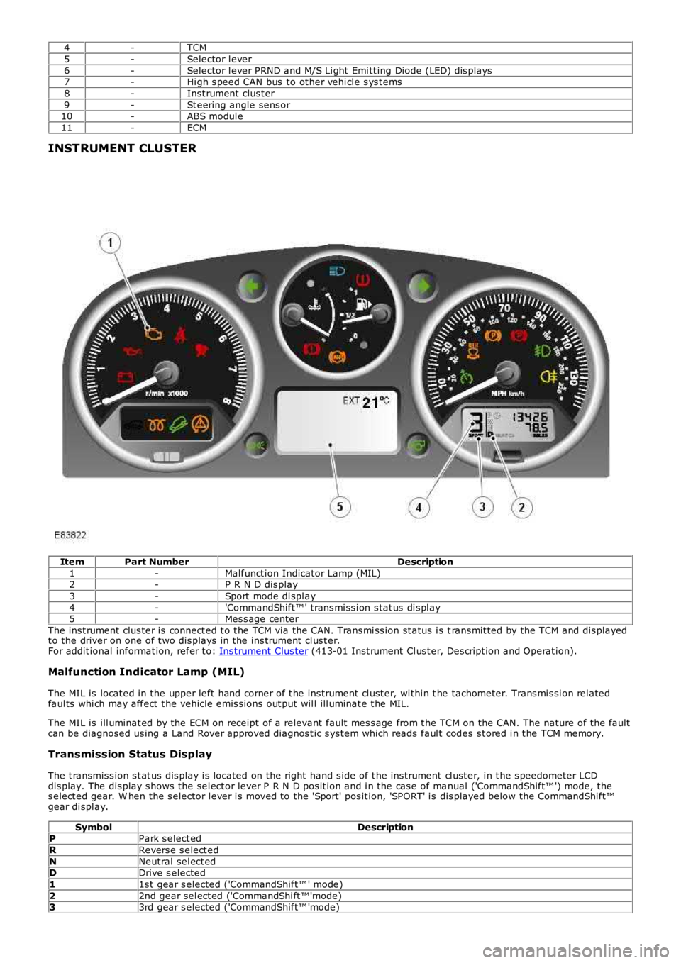
ItemPart NumberDescription
1-Malfunct ion Indicator Lamp (MIL)2-P R N D dis play
3-Sport mode di spl ay
4-'CommandShift™ ' trans mi ss i on s tat us di s pl ay5-Mes s age center
The ins t rument clus ter is connect ed t o t he TCM via the CAN. Trans mi ss ion st atus i s trans mit ted by the TCM and dis playedt o the driver on one of t wo dis plays in the ins trument cl us t er.For addit ional informat ion, refer t o: Ins t rument Clus ter (413-01 Inst rument Cl us t er, Des cript ion and Operat ion).
Malfunction Indicator Lamp (MIL)
The MIL is locat ed in the upper left hand corner of t he ins trument cl ust er, wi thi n the tachometer. Trans mi s si on rel atedfaul ts whi ch may affect t he vehicle emis si ons out put wil l ill uminat e t he MIL.
The MIL is ill uminat ed by the ECM on receipt of a relevant fault mes s age from t he TCM on the CAN. The nature of the faultcan be diagnosed us ing a Land Rover approved diagnos t ic s ys tem which reads faul t codes s t ored i n t he TCM memory.
Transmission Status Display
The t ransmis s ion s t at us dis play i s located on the right hand s ide of t he ins trument cl ust er, i n t he s peedometer LCDdis play. The dis play s hows the sel ect or lever P R N D pos it ion and i n the cas e of manual ('CommandShift™ ') mode, thes elect ed gear. W hen the s elector l ever i s moved to the 'Sport' pos it ion, 'SPORT' i s dis played below the CommandShift™gear di spl ay.
SymbolDescriptionPPark s elect ed
RRevers e s elect ed
NNeutral sel ect edDDrive s elected
11s t gear s elected ('CommandShift™ ' mode)
22nd gear sel ect ed ('CommandShi ft ™'mode)33rd gear s elected ('CommandShift™ 'mode)
Page 1294 of 3229
W hen movi ng from a st andst il l, ups hi ft s can be pre-s el ect ed by making '+' s el ect ions wi th the s elect or l ever for thenumber of ups hifts requi red. The TCM t hen performs t he reques ted number of upshi ft s when appropri at e s hift points arereached. For exampl e; when moving off in 1s t gear, if 3 '+' s elect ions are made i n quick s ucces si on, t he TCM willautomat ically ups hift t hrough the gears to 4t h gear as t he vehi cl e accelerates , wit hout any furt her s electi ons bei ng made.
Cooling
Cooling mode is act ivated when t he TCM det ect s exces s ively hi gh trans mi s si on fl uid or engine coolant temperatures . W hent hi s mode i s act ive torque converter l ock-up is acti vat ed earl ier t o mi ni mi ze a further ris e in fl uid and/or engine coolantt emperature and ass i st flui d cool ing.
Hill Descent Control (HDC)
The HDC mode as s is t s t he ABS module i n cont rol li ng the downhil l speed of t he vehi cl e. W hen HDC i s acti ve, t he TCMs elect s t he mos t appropri at e gear for t he descent to maxi mi ze engi ne braking.
Maximum engi ne braking i s applied us i ng a s hift map which i nit iat es later ups hift s and earl y downshi ft s .
Cruise
W hen s peed cont rol i s act ivated, t he TCM receives a speed control acti ve mes s age on the hi gh s peed CAN bus . The TCMact ivat es a s peed cont rol map whi ch minimizes up and down s hifts .
Crui se mode is act ive when s peed cont rol is sel ect ed on and t he transmis s ion i s in drive 'D', s port 'S', HDC or Terrai nRespons e Gras s /gravel /s now program. Unique cruis e maps overri de the current mode t o provide a smoot h driving feel andmode resel ect ion.
Limp Home
If a transmis s ion faul t is det ect ed by t he TCM, the TCM adopt s a l imp home s trategy and a mes s age 'TRANSMISSIONFAULT LIMITED GEARS AVAILABLE' i s dis played in the mes s age cent er. If the fault has an effect on engi ne emis s ions , theMIL in the i nst rument clus t er wi ll als o be il luminat ed.
In li mp home mode, P, R and N functi ons operate normall y (i f the fault al lows t hes e s elect ions) and t he TCM locks t het ransmis s ion i n 3rd gear t o all ow t he dri ver t o t ake the vehicle to a Land Rover deal er or approved repai rer. Torqueconvert er lock-up i s dis abled and reverse-lock-out wil l not funct ion.
If the vehicle is s t opped and s ubsequentl y res tarted in t he li mp home mode condi ti on, t he TCM operat es normall y unti l thefaul t which caus ed t he condi ti on is det ect ed agai n.
Coast
Coast mode provides earli er downs hifts during coast ing dependant on out put shaft decelerat ion rate to improve driveabili tyand refinement by avoi ding negati ve to pos it ive driveli ne torque revers als t rans mi ssion during t he downshi ft s .
Fast Off Recognition
Fast off recogni ti on is act ivated when t he TCM det ect s t hat t he dri ver has releas ed the accel erat or pedal qui ckl y. This isdetected by the TCM monit oring for a high level of negat ive pedal angl e from ECM s ignals on t he high speed CAN bus . Ift hi s condi ti on is det ect ed, t he TCM hol ds the current gear rati o to allow the driver t o compl ete the manoeuvre wi thout t heneed for a downs hift. The mode can remain acti ve for a predet ermined lengt h of ti me or i f the driving s t yl e remainspass i ve.
Fast off recogni ti on mode as si s ts vehicle st abili ty and is us ed i n conjunct ion a lateral accel erat ion i nput duri ng corneri ng tomaint ain t he current gear unti l the corner is negot iated.
Uphill and Trailer
Uphill and t rai ler mode can be acti ve when the trans mi s si on is operat ing in normal, s port or Terrai n Res pons e modes .W hen t he vehicle i s pull ing a t rai ler or dri vi ng up an i ncl ine, the TCM det ects t he i ncreas ed res i st ance by monit oring enginet orque and s peed s i gnal s received from the ECM on the hi gh s peed CAN bus and als o t rans mis s ion out put s haft s peeds ens or s ignals . Uphi ll and t rai ler mode wi ll provide downs hift s t o prevent a drop in t rans mi ss i on torque out put andmaint ain driving force.
Downhill
Downhill mode can be act ive when t he t ransmis s ion i s operati ng in normal, s port or Terrain Res pons e modes . W hen t hevehi cl e i s descendi ng an i ncl ine t he TCM detect s a reducti on in res is t ance by moni toring engine t orque and s peed si gnal sreceived from the ECM on t he high s peed CAN bus and als o t rans mis s ion out put shaft speed s ensor s ignals . Downhill modeas si st s engine braki ng by s elect ing an appropriat e gear reduci ng the load required on t he brakes .
Wide Throttle
W i de open thrott le mode operates for part thrott le ups hifts and ki ck-down ups hifts . It provides cons i st ent wide opent hrott le ups hift performance under all driving condit ions. The full engine s peed range is used i n all driving modes ; normal ,s port, hi ll modes and Commands hi ft . Compens at ion i s used for delays (hydrauli c and electroni c) in gear change reques t togear change s tart to provi de s mooth changes and correct shi ft point correct ion.
Terrain Response
The Terrai n Res pons e s ys tem has a unique s et of shi ft maps for each of t he Terrai n Res pons e programs . Thes e programsoverri de exis ti ng modes; for exampl e when HDC is acti ve and the 'Sand', 'Mud and Ruts ' or 'Grass /Gravel/Snow' programsare sel ect ed, a specific Terrain Res ponse map is used, not the HDC mode s hift map detai led previ ous ly.
Page 1295 of 3229
Reverse Lock-Out
If the s elector l ever is moved from N to R and t he vehi cl e i s travel li ng forwards , revers e s electi on is prevent ed if t hevehi cl e s peed is 11 km/h (6.8 mph) or more. W hen revers e lock-out is act ivated, t he cl utch (C3) is released wit houtenergizing sol enoid (SLC3), preventi ng t he transmis si on from sel ect ing reverse gear.
TRANSMISSION FAULT STATUS
If the TCM det ect s a fault wi th the t rans mi ss ion sys tem, it wi ll enter a defaul t (l imp home) mode to prevent furt herdamage to the trans mi ss i on and allow the vehicl e to be dri ven. If pos s ibl e revers e gear wil l be avai lable and al s o 3rd gearonly.
W hen a fault i s detected a high s peed CAN mes s age is s ent from the TCM and is recei ved by the i nst rument clus ter. Theins t rument clus ter il lumi nat es t he MIL (i f required) and di spl ays an appl icabl e mes sage in t he mes s age cent er.For addit ional informat ion, refer t o: Informat ion and Mes s age Cent er (413-08 Informat ion and Mes s age Cent er, Des cript ionand Operat ion).
Some t rans mis s ion fault s may not il lumi nat e t he MIL or dis play a fault mes s age, but t he driver may not ice a reduct ion i ns hift quali ty.
ENGINE SPEED AND TORQUE MONITORING
The ECM const antl y s uppl ies t he TCM wi th informati on on engine s peed and torque through mes s ages on the CAN bus. TheTCM us es t hi s informat ion t o calculat e the correct and appropriat e t imi ng of shi ft changes .
If the mes s ages are not received by t he ECM, the TCM wil l impl ement a back-up st rat egy to prot ect t he transmis s ion fromdamage and all ow t he vehi cl e t o be dri ven.
In the event of an engi ne s peed or t orque s i gnal fai lure, t he t rans mis s ion wi ll adopt the el ect ri cal li mp home mode wit ht he trans mi s si on operati ng in a fixed gear.
TOWING FOR RECOVERY
W ARNING: Ens ure that t he remot e hands et remains docked whi ls t the vehicl e is bei ng towed. Removing t he remot ehands et wil l engage t he s teering l ock, which wi ll prevent the vehicle from s t eering correct ly.
If the engine cannot be run whi ls t the vehicl e is bei ng towed, t here wi ll be no power ass i st ance for the st eeri ng or brakes .This wi ll res ult in great er effort being requi red t o s t eer or s low the vehicle, and great ly i ncreas ed s t oppi ng dis tances.
CAUTION: The vehicle s hould only be towed wit h four wheels on the ground. Towing wi th two wheel s on t he groundwil l res ult i n s erious damage t o t he t ransmis s ion.
The vehi cl e s houl d only be towed for a maximum of 80 km (50 miles ), at a maximum s peed of 80 km/h (50 mph). Towi ngfor a greater dis t ance, or at a higher speed may res ul t in serious damage t o t he trans mi s si on.
• NOTE: The recommended recovery met hod is by trailer or recovery vehicle.
Secure t he towi ng att achment from the recovery vehicl e to the front t owing eye.
Ins ert the remote hands et in t he s tart cont rol module and swi tch on the i gni ti on by pres s ing t he s tart/s top but ton once.
• NOTE: Leavi ng the ignit ion s wit ched on for extended peri ods will cause the bat tery t o drain.
Apply t he foot brake, and move t he s el ect or lever to the neutral 'N' pos i ti on. W it h t he foot brake s ti ll appl ied, rel eas e t hepark brake. If elect rical power t o the sel ect or is not avai lable, t he emergency releas e l ever on t he s elect or lever can beus ed to releas e t he int erlock s olenoid.
The vehi cl e can be t owed a maximum of 80 km (50 mil es ) at a maxi mum speed of 80 km/h (50 mph).
Park t he vehicle on firm, l evel ground. Appl y the park brake and move t he s elector lever t o the park 'P' posi ti on.
Swit ch off t he ignit ion and remove t he remot e handset .
CAUTION: The vehicle cannot be towed i n a revers e direct ion.
Page 1296 of 3229
Publi s hed: 11-May-2011
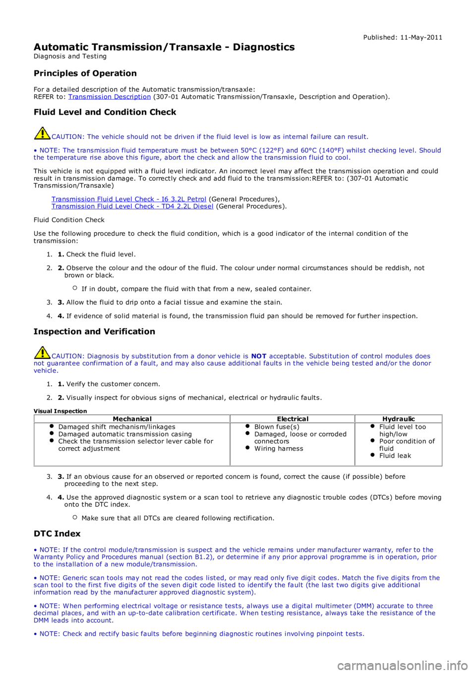
Automatic Transmission/Transaxle - Diagnostics
Diagnosi s and Tes ti ng
Principles of Operation
For a detail ed descripti on of the Aut omati c t ransmis s ion/t rans axl e:REFER to: Trans mi ss i on Descri pti on (307-01 Aut omat ic Trans mi ss ion/Transaxle, Des cript ion and O perati on).
Fluid Level and Condition Check
CAUTION: The vehicle s hould not be driven if t he fluid level i s low as int ernal failure can resul t.
• NOTE: The t rans mis s ion fluid temperat ure mus t be bet ween 50°C (122°F) and 60°C (140°F) whil s t checki ng level. Shouldt he temperat ure ri se above t his figure, abort t he check and al low t he t rans mis s ion flui d to cool .
This vehicle is not equi pped wit h a flui d level indicator. An incorrect l evel may affect the t rans mi ss i on operati on and couldres ult i n t rans mis s ion damage. To correct ly check and add flui d t o the trans mi s si on:REFER to: (307-01 Automat icTrans mis s ion/Transaxle)
Transmis s ion Flui d Level Check - I6 3.2L Petrol (General Procedures ),Transmis s ion Flui d Level Check - TD4 2.2L Di es el (General Procedures ).
Fluid Condi ti on Check
Us e t he fol lowing procedure to check the flui d condi ti on, whi ch is a good i ndicat or of the i nternal condi ti on of thet ransmis s ion:
1. Check t he fluid level .1.
2. Observe the col our and t he odour of t he fl uid. The col our under normal circums t ances s houl d be reddi sh, notbrown or black.
If in doubt, compare t he fluid wit h t hat from a new, s ealed cont ainer.
2.
3. All ow t he fl ui d t o dri p onto a faci al t is s ue and examine t he s tai n.3.
4. If evidence of sol id materi al is found, t he transmis s ion fluid pan should be removed for furt her ins pecti on.4.
Inspection and Verification
CAUTION: Di agnos is by s ubs ti tut ion from a donor vehicle is NO T acceptabl e. Subs ti tut ion of cont rol modules doesnot guarant ee confirmat ion of a faul t, and may als o caus e addit ional fault s i n t he vehi cl e being t est ed and/or t he donorvehi cl e.
1. Verify t he cus t omer concern.1.
2. Vis ually ins pect for obvious s igns of mechani cal , el ect ri cal or hydrauli c fault s .2.
Visual Inspection
MechanicalElectricalHydraulicDamaged s hift mechanis m/li nkagesDamaged automat ic t rans mi ss ion cas ingCheck the t rans mi ss ion sel ect or lever cable forcorrect adjus t ment
Bl own fus e(s)Damaged, loos e or corrodedconnect orsW iring harnes s
Fluid level t oohigh/l owPoor condit ion offl uidFluid leak
3. If an obvious cause for an obs erved or report ed concern is found, correct t he caus e (if pos s ible) beforeproceeding t o t he next s t ep.3.
4. Us e the approved di agnos ti c s ys t em or a s can t ool t o ret rieve any diagnos t ic t rouble codes (DTCs ) before movingont o t he DTC index.
Make s ure t hat all DTCs are cl eared fol lowing recti fi cat ion.
4.
DTC Index
• NOTE: If the control modul e/t rans mis s ion i s s uspect and the vehicle remai ns under manufacturer warrant y, refer t o t heW arranty Pol icy and Procedures manual (s ect ion B1.2), or determine i f any pri or approval programme is in operat ion, pri ort o the ins tall ati on of a new module/transmis s ion.
• NOTE: Generic scan t ool s may not read the codes li st ed, or may read only fi ve digit codes . Mat ch the five di git s from t hes can tool to the firs t fi ve di git s of the seven digi t code l is ted to ident ify t he faul t (t he las t t wo digi ts gi ve addi ti onalinformat ion read by the manufact urer approved diagnos t ic s ys tem).
• NOTE: W hen performing el ect ri cal volt age or resi s tance tes t s, al ways us e a digit al mult imet er (DMM) accurate to threedeci mal places , and wi th an up-to-date cali brat ion cert ificate. W hen t es ti ng res is t ance, always take t he res i st ance of t heDMM leads int o account.
• NOTE: Check and recti fy bas ic faul ts before beginni ng diagnos t ic rout ines i nvol vi ng pinpoint t es t s.
Page 1298 of 3229
Publi s hed: 11-May-2011
Automatic Transmission/Transaxle - Transmission Fluid Level CheckI6 3.2L
Petrol
General Procedures W ARNING: Observe due care when drai ning, as the flui d can be very hot .
Ens ure t hat the aut omat ic trans mi s si on is in 'P' and t he handbrake is
ful ly appli ed.
1.
Remove t he air cleaner hous ing.
Refer t o: Air Cleaner (303-12B Intake Ai r Dis tribut ion and Fil tering -
TD4 2.2L Dies el, Removal and Inst all ati on).
2.
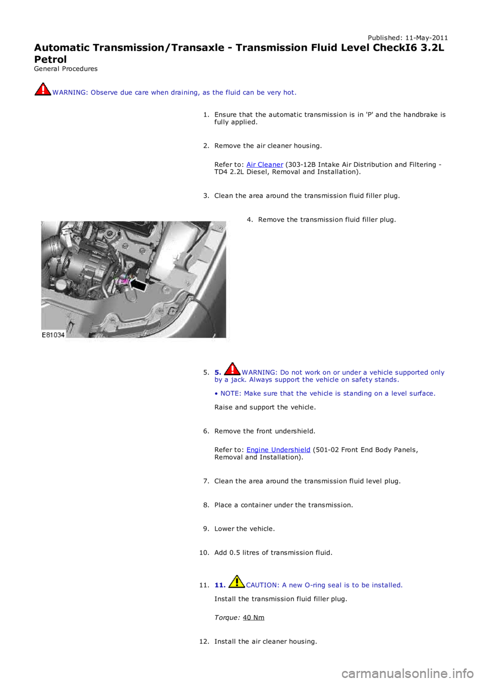
Clean t he area around the trans mi s si on fl uid fil ler plug.
3. Remove t he transmis si on fluid fil ler plug.
4.
5. W ARNING: Do not work on or under a vehi cle s upported onl y
by a jack. Al ways support t he vehi cl e on s afet y s tands .
• NOTE: Make s ure that t he vehi cl e is st andi ng on a level s urface.
Rais e and s upport t he vehi cl e.
5.
Remove t he front unders hiel d.
Refer t o: Engi ne Unders hi eld (501-02 Front End Body Panel s ,
Removal and Ins tall ati on).
6.
Clean t he area around the trans mi s si on fl uid l evel plug.
7.
Place a contai ner under the t rans mi ss i on.
8.
Lower the vehicle.
9.
Add 0.5 li tres of trans mi s si on fl uid.
10.
11. CAUTION: A new O-ring s eal is t o be ins tall ed.
Inst all t he transmis si on fluid fil ler plug.
T orque: 40 Nm 11.
Inst all t he air cleaner hous ing.
12.
Page 1300 of 3229
Publi s hed: 11-May-2011
Automatic Transmission/Transaxle - Transmission Fluid Drain and RefillI6
3.2L Petrol
General Procedures W ARNING: Observe due care when drai ning, as the flui d can be very hot .
Ens ure t hat the aut omat ic trans mi s si on is in 'P' and t he handbrake is
ful ly appli ed.
1.
Remove t he air cleaner hous ing.
Refer t o: Air Cleaner (303-12B Intake Ai r Dis tribut ion and Fil tering -
TD4 2.2L Dies el, Removal and Inst all ati on).
2.
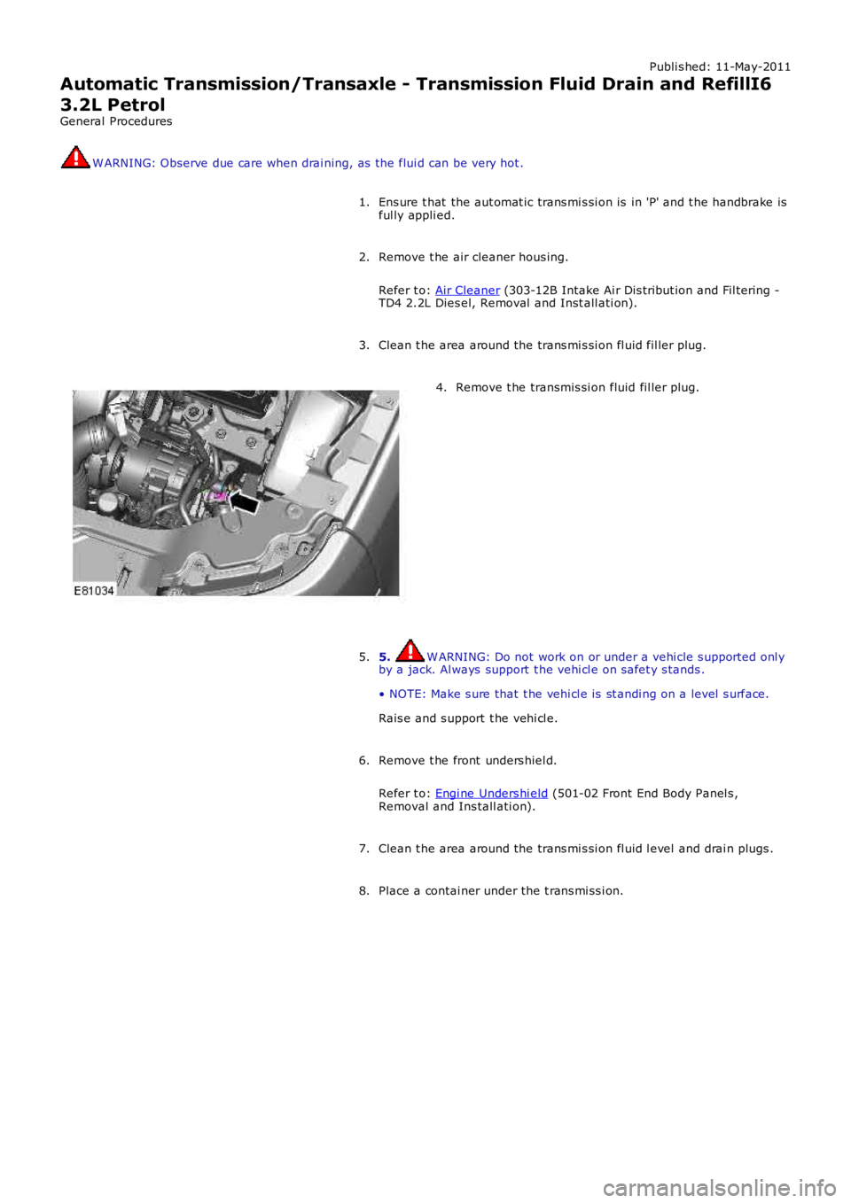
Clean t he area around the trans mi s si on fl uid fil ler plug.
3. Remove t he transmis si on fluid fil ler plug.
4.
5. W ARNING: Do not work on or under a vehi cle s upported onl y
by a jack. Al ways support t he vehi cl e on s afet y s tands .
• NOTE: Make s ure that t he vehi cl e is st andi ng on a level s urface.
Rais e and s upport t he vehi cl e.
5.
Remove t he front unders hiel d.
Refer t o: Engi ne Unders hi eld (501-02 Front End Body Panel s ,
Removal and Ins tall ati on).
6.
Clean t he area around the trans mi s si on fl uid l evel and drai n plugs .
7.
Place a contai ner under the t rans mi ss i on.
8.
Page 1303 of 3229
Publi s hed: 11-May-2011
Automatic Transmission/Transaxle - Transmission Fluid Level CheckTD4
2.2L Diesel
General Procedures W ARNING: Observe due care when drai ning, as the flui d can be very hot .
Ens ure t hat the aut omat ic trans mi s si on is in 'P' and t he handbrake is
ful ly appli ed.
1.
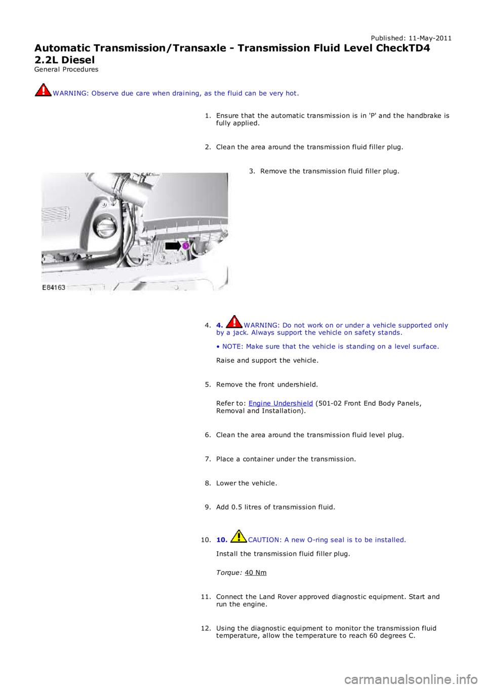
Clean t he area around the trans mi s si on fl uid fil ler plug.
2. Remove t he transmis si on fluid fil ler plug.
3.
4. W ARNING: Do not work on or under a vehi cle s upported onl y
by a jack. Al ways support t he vehi cl e on s afet y s tands .
• NOTE: Make s ure that t he vehi cl e is st andi ng on a level s urface.
Rais e and s upport t he vehi cl e.
4.
Remove t he front unders hiel d.
Refer t o: Engi ne Unders hi eld (501-02 Front End Body Panel s ,
Removal and Ins tall ati on).
5.
Clean t he area around the trans mi s si on fl uid l evel plug.
6.
Place a contai ner under the t rans mi ss i on.
7.
Lower the vehicle.
8.
Add 0.5 li tres of trans mi s si on fl uid.
9.
10. CAUTION: A new O-ring s eal is t o be ins tall ed.
Inst all t he transmis si on fluid fil ler plug.
T orque: 40 Nm 10.
Connect t he Land Rover approved diagnos t ic equipment. St art and
run the engine.
11.
Us ing t he diagnos ti c equi pment t o moni tor t he transmis s ion fluid
t emperature, al low the t emperat ure t o reach 60 degrees C.
12.