2006 LAND ROVER FRELANDER 2 clutch
[x] Cancel search: clutchPage 1100 of 3229
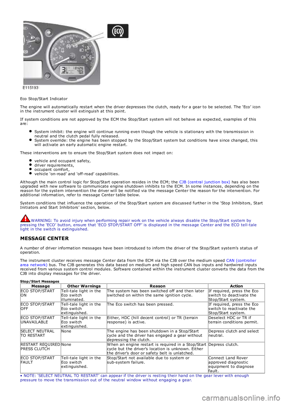
Eco Stop/St art Indicat or
The engi ne wi ll automat ically res tart when the driver depress es t he clut ch, ready for a gear t o be sel ect ed. The ‘Eco’ iconin the i nst rument clus t er will exti ngui s h at thi s point.
If sys tem condi ti ons are not approved by the ECM the St op/St art s yst em will not behave as expect ed, exampl es of thisare:
Syst em i nhibit : the engi ne wil l conti nue running even t hough t he vehicle i s s tat ionary wit h t he trans mi s si on inneut ral and t he clut ch pedal ful ly released.Syst em override: t he engi ne has been st opped by the St op/St art s ys t em but condi ti ons have s i nce changed, t hi swil l act ivate an earl y aut omat ic engine rest art .
Thes e intervent ions are to ens ure the St op/St art s ys t em does not impact on:
vehi cl e and occupant s afety,dri ver requi rement s,occupant comfort ,vehi cl e ‘on-road’ and ‘off-road’ capabi lit ies .
Alt hough the mai n cont rol l ogi c for St op/Start operati on res ides i n t he ECM; the CJB (cent ral juncti on box) has al so beenupgraded wit h new s oftware to communi cat e engine s hutdown i nhibit s t o t he ECM. In s ome ins tances , dependi ng on thereas on for t he s yst em intervent ion t he dri ver wi ll be not ified via the mes s age Center t he reas on for t he int ervent ion. Foraddi ti onal i nformat ion, refer to mes sage Center t able below.
Syst em condit ions t hat i nfluence t he operati on of the St op/Start s ys t em are dis cus s ed further i n the ‘Stop Inhibit ors , St artIni ti ators and Start Inhibi tors ’ s ect ion, below.
W ARNING: To avoi d injury when performing repai r work on t he vehicle al ways di s abl e the Stop/St art s ys tem bypres s ing t he ‘ECO’ butt on, ens ure that ‘ECO STOP/START OFF’ is di s pl ayed in t he mes sage Cent er and the ECO tel l-taleli ght in t he s wit ch is ext inguis hed.
MESSAGE CENTER
A number of dri ver i nformat ion mess ages have been i ntroduced t o inform the driver of the St op/St art s ys t em’s s t atus ofoperati on.
The ins t rument clus ter receives mes s age Cent er dat a from the ECM via t he CJB over t he medi um s peed CAN (cont roll erarea net work) bus. The CJB generat es this dat a bas ed on medium and high s peed CAN bus i nput s and hardwired i nput sreceived from various s yst em control modul es. Software cont ained wi thin the ins trument cl us t er convert s the dat a from theCJB int o dis play mes s ages for t he dri ver.
Stop/Start Messages
MessageOther WarningsReasonAction
ECO STOP/STARTONTell-t al e l ight in theEco s wit chil lumi nat ed.
The s ys tem has been swi tched off and t hen lat ers wi tched on wi thin the s ame ignit ion cycl e.If required, pres s the Ecos wi tch t o deact ivat e theSt op/St art s ys t em.ECO STOP/STARTOFFTell-t al e l ight in theEco s wit chexti nguis hed.
The Eco s wit ch has been pres sed.If required, pres s the Ecos wi tch t o react ivate theSt op/St art s ys t em.
ECO STOP/STARTUNAVAILABLETell-t al e l ight in theEco s wit chexti nguis hed.
Ei ther, HDC (hi ll decent cont rol ) or TR (t errainrespons e) is acti ve.Des elect HDC or TR i ft errain condit ions permi t.
SELECT NEUTRALTO RESTARTNoneThe engine has been s hutdown i n a St op/Startcycl e and t he dri ver has engaged a gear wi thoutdepres s ing t he clut ch.
Depres s cl ut ch and s electneut ral.
RESTART REQ UIREDPRESS CLUTCHNoneW hen an engi ne res t art i s required in a Stop/St artcycl e but t he driver’s l ocati on is unknown. Eit hert he dri ver’s door or s afety bel t is unl at ched.
Depres s cl ut ch.
ECO STOP/STARTFAULTTell-t al e l ight in theEco s wit chexti nguis hed.
St op/Start not avail able due t o s yst em ors ub-s ys tem fai lure.Connect Land Roverapproved diagnos ti cequipment t o diagnosefault .• NOTE: ‘SELECT NEUTRAL TO RESTART’ can appear if t he dri ver i s res t ing t heir hand on t he gear l ever wi th enoughpres s ure t o move t he t rans mis s ion out of t he neut ral wi ndow wit hout engagi ng a gear.
Page 1106 of 3229
CAUTION: To avoid damage/malfuncti oni ng of the BMS module, always us e a s uit able body ground point rather thant he bat t ery negat ive terminal when connect ing a s lave power supply.
For addit ional informat ion, refer t o: Batt ery (414-01 Bat tery, Mounti ng and Cables , Diagnos is and Tes t ing).
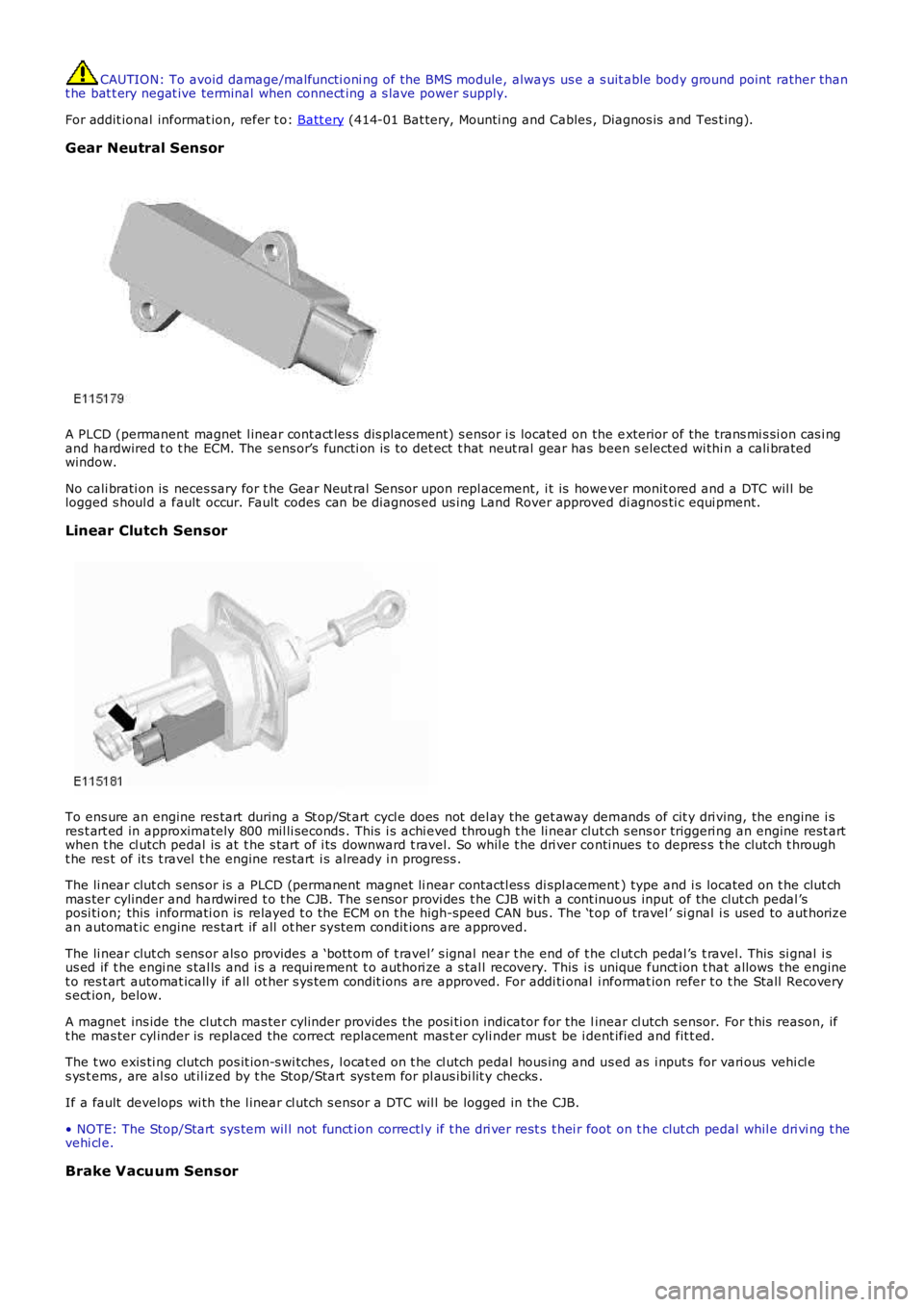
Gear Neutral Sensor
A PLCD (permanent magnet l inear cont act les s dis placement) s ensor i s located on the exterior of the trans mi s si on cas i ngand hardwired t o t he ECM. The sens or’s functi on is t o det ect t hat neut ral gear has been s elected wi thi n a cali bratedwindow.
No cali brati on is neces sary for t he Gear Neut ral Sensor upon repl acement, i t is however monit ored and a DTC wil l belogged s houl d a fault occur. Fault codes can be diagnos ed us ing Land Rover approved di agnos ti c equi pment.
Linear Clutch Sensor
To ens ure an engine res tart during a St op/St art cycl e does not del ay the get away demands of cit y dri ving, the engine i sres t art ed in approximately 800 mil li seconds . This i s achi eved through t he li near clut ch s ens or triggeri ng an engine rest artwhen t he cl utch pedal is at t he s tart of i ts downward t ravel. So whil e t he dri ver conti nues t o depres s t he clutch t hrought he res t of it s t ravel t he engine rest art i s already i n progress .
The li near clut ch s ens or is a PLCD (permanent magnet li near contactl es s di spl acement) type and i s located on t he clut chmas ter cylinder and hardwired t o t he CJB. The s ensor provi des t he CJB wi th a cont inuous input of the clut ch pedal ’sposi ti on; this informati on is relayed t o t he ECM on t he high-speed CAN bus . The ‘t op of travel ’ si gnal i s used to aut horizean automat ic engine res tart if all ot her s ys tem condit ions are approved.
The li near clut ch s ens or als o provides a ‘bott om of t ravel’ s ignal near t he end of the cl ut ch pedal ’s t ravel. This si gnal i sus ed if t he engi ne s tal ls and i s a requi rement t o authori ze a s tal l recovery. This is unique funct ion t hat allows the enginet o res t art automat ically if all ot her s ys tem condit ions are approved. For addi ti onal i nformat ion refer t o t he Stall Recoverys ect ion, below.
A magnet ins ide the clut ch mas ter cylinder provides t he posi ti on indicator for the linear cl utch s ensor. For t his reason, ift he mas ter cyl inder is replaced the correct replacement mas t er cyli nder mus t be i dent ified and fit t ed.
The t wo exis ti ng clutch pos it ion-s wi tches, l ocat ed on t he cl utch pedal hous ing and us ed as i nput s for vari ous vehi cl es ys t ems , are al so ut il ized by t he Stop/Start sys tem for pl aus ibi lit y checks .
If a fault develops wi th the l inear cl utch s ensor a DTC wil l be logged in the CJB.
• NOTE: The Stop/Start sys tem wil l not funct ion correctl y if t he dri ver rest s t hei r foot on t he clut ch pedal whil e dri vi ng t hevehi cl e.
Brake Vacuum Sensor
Page 1215 of 3229
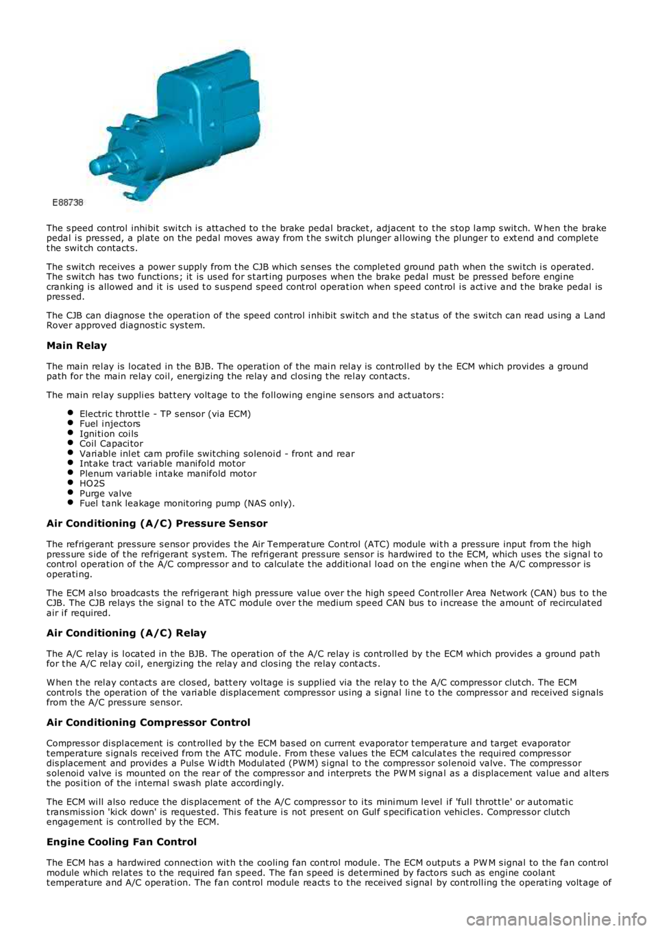
The s peed control inhibit swi tch i s att ached to t he brake pedal bracket , adjacent t o t he s top l amp s wit ch. W hen the brakepedal i s pres s ed, a pl ate on the pedal moves away from t he s wit ch plunger al lowing the pl unger to ext end and completet he swit ch contact s.
The s wit ch receives a power s upply from t he CJB which s enses the complet ed ground path when the s wi tch i s operated.The s wit ch has two functi ons ; it is us ed for s t art ing purpos es when the brake pedal mus t be pres s ed before engi necranking i s allowed and it is used t o s us pend speed cont rol operat ion when s peed cont rol i s act ive and t he brake pedal ispres s ed.
The CJB can diagnos e t he operat ion of t he speed control i nhibit s wi tch and t he s tat us of the s wi tch can read us ing a LandRover approved diagnost ic sys tem.
Main Relay
The main rel ay is l ocat ed in the BJB. The operati on of the mai n rel ay is cont roll ed by t he ECM which provi des a groundpath for the main relay coil , energi zing t he rel ay and cl osi ng t he rel ay cont act s.
The main rel ay suppli es bat t ery volt age to the foll owing engine s ensors and act uators:
Electric t hrot tl e - TP s ensor (via ECM)Fuel i njectorsIgni ti on coi lsCoil Capaci torVari abl e inl et cam profile swit ching sol enoi d - front and rearInt ake tract variable mani fol d mot orPlenum variable i ntake manifold motorHO2SPurge valveFuel t ank leakage monit oring pump (NAS onl y).
Air Conditioning (A/C) Pressure Sensor
The refri gerant pres sure s ens or provides t he Air Temperat ure Cont rol (ATC) module wit h a press ure input from t he highpres s ure s ide of t he refrigerant s ys t em. The refri gerant press ure s ens or is hardwired to the ECM, which us es t he s ignal t ocont rol operat ion of t he A/C compress or and to cal cul at e t he addit ional l oad on t he engi ne when t he A/C compress or isoperati ng.
The ECM al so broadcas ts the refrigerant high press ure val ue over t he high s peed Controller Area Network (CAN) bus t o t heCJB. The CJB relays the si gnal t o t he ATC module over t he medium speed CAN bus t o i ncreas e the amount of recircul at edair i f required.
Air Conditioning (A/C) Relay
The A/C rel ay is l ocat ed in the BJB. The operati on of the A/C relay i s cont roll ed by t he ECM whi ch provi des a ground pat hfor t he A/C rel ay coi l, energizi ng the relay and clos ing the relay cont acts .
W hen t he rel ay cont act s are clos ed, batt ery vol tage i s s uppl ied via the relay t o t he A/C compress or clut ch. The ECMcont rol s the operat ion of t he vari abl e dis placement compress or us ing a s i gnal li ne to t he compress or and received s ignalsfrom the A/C pres s ure sens or.
Air Conditioning Compressor Control
Compres s or di spl acement is cont roll ed by t he ECM bas ed on current evaporator t emperature and target evaporat ort emperature s ignals received from t he ATC module. From thes e values t he ECM calcul ates t he requi red compres s ordis placement and provi des a Puls e W idt h Modul ated (PW M) s i gnal t o t he compress or s olenoi d valve. The compress ors olenoi d valve i s mounted on the rear of t he compres s or and i nterprets the PW M s ignal as a dis placement val ue and alt erst he pos i ti on of the i nternal s wash plate accordi ngl y.
The ECM wi ll als o reduce t he dis placement of the A/C compres s or to i ts mini mum l evel i f 'ful l throt t le' or aut omati ct ransmis s ion 'ki ck down' is request ed. Thi s feat ure i s not pres ent on Gul f s pecificati on vehi cl es. Compress or clutchengagement is cont roll ed by t he ECM.
Engine Cooling Fan Control
The ECM has a hardwired connect ion wit h t he cooli ng fan cont rol module. The ECM output s a PW M s ignal to the fan cont rolmodule whi ch rel at es t o t he required fan s peed. The fan s peed is det ermi ned by factors s uch as engi ne coolantt emperature and A/C operati on. The fan cont rol module react s t o t he received s ignal by cont roll ing t he operat ing volt age of
Page 1272 of 3229
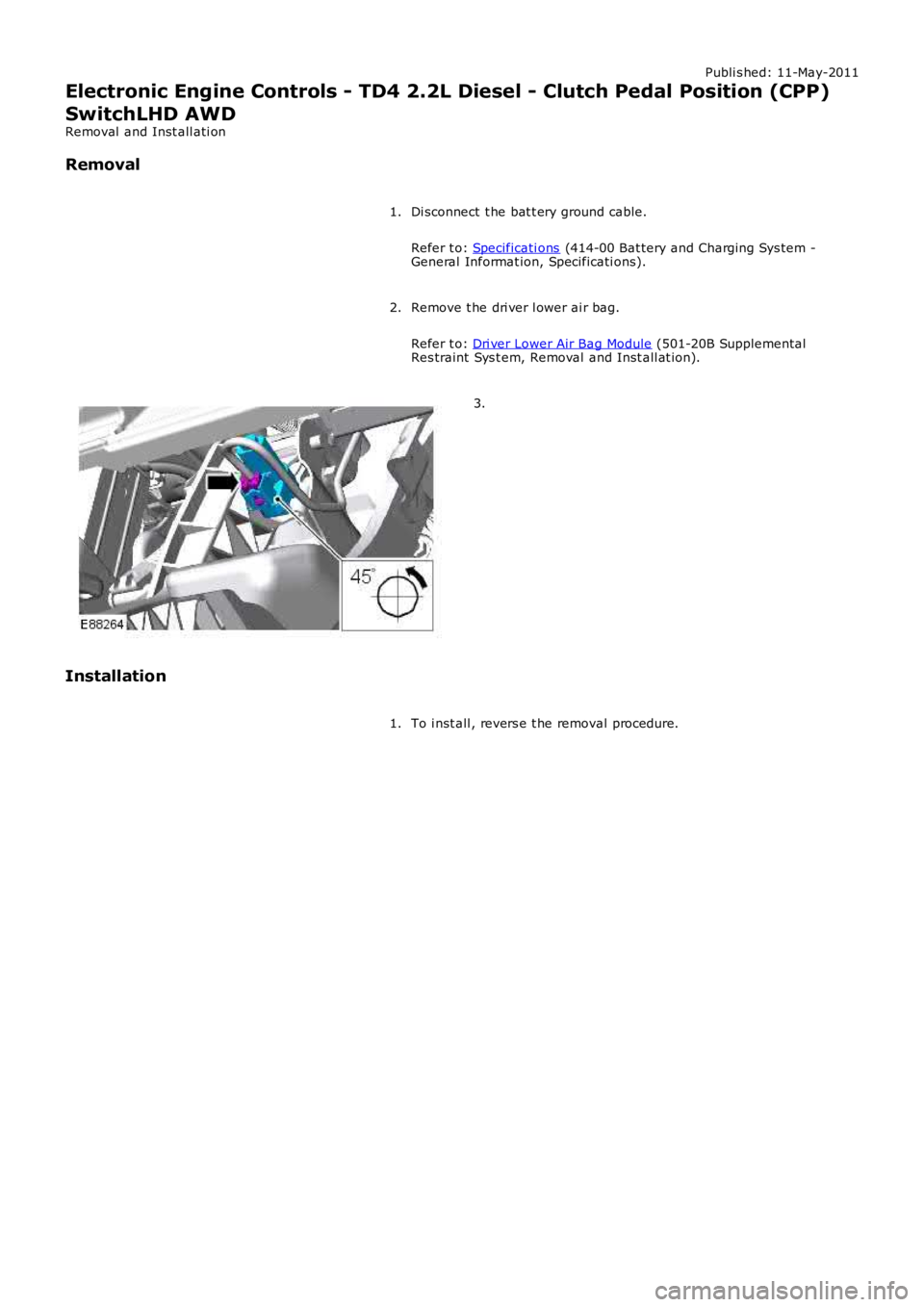
Publi s hed: 11-May-2011
Electronic Engine Controls - TD4 2.2L Diesel - Clutch Pedal Position (CPP)
SwitchLHD AWD
Removal and Inst all ati on
Removal
Di sconnect t he bat t ery ground cable.
Refer t o: Specificati ons (414-00 Bat tery and Charging Sys tem -General Informat ion, Specificati ons).
1.
Remove t he dri ver l ower ai r bag.
Refer t o: Dri ver Lower Air Bag Module (501-20B SupplementalRes traint Sys t em, Removal and Inst all at ion).
2.
3.
Installation
To i nst all , revers e t he removal procedure.1.
Page 1273 of 3229
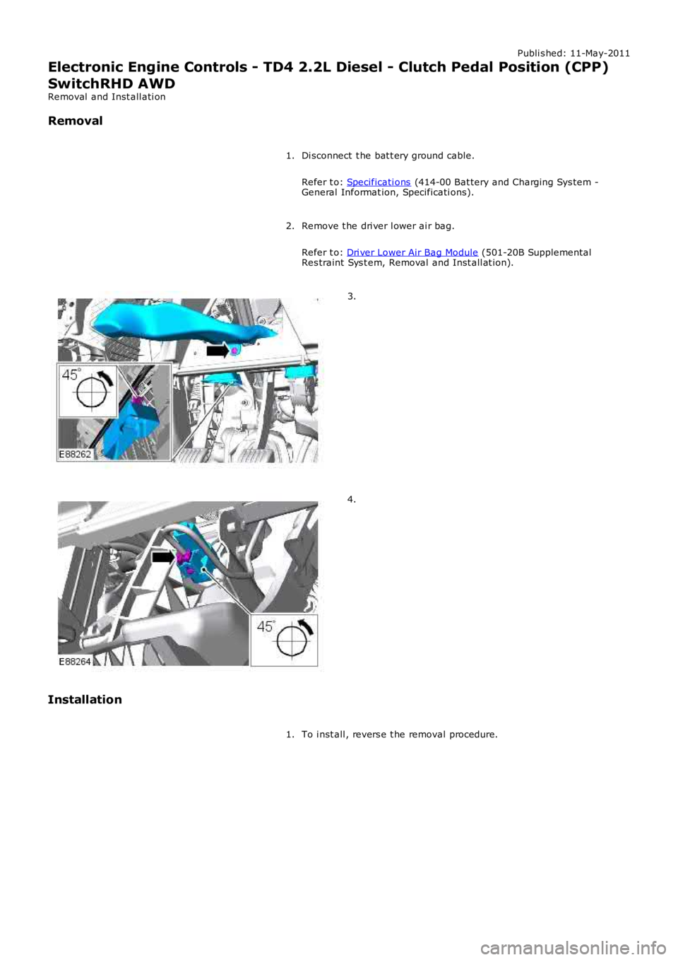
Publi s hed: 11-May-2011
Electronic Engine Controls - TD4 2.2L Diesel - Clutch Pedal Position (CPP)
SwitchRHD AWD
Removal and Inst all ati on
Removal
Di sconnect t he bat t ery ground cable.
Refer t o: Specificati ons (414-00 Bat tery and Charging Sys tem -
General Informat ion, Specificati ons).
1.
Remove t he dri ver l ower ai r bag.
Refer t o: Dri ver Lower Air Bag Module (501-20B Supplemental
Res traint Sys t em, Removal and Inst all at ion).
2. 3.
4.
Installation To i nst all , revers e t he removal procedure.
1.
Page 1282 of 3229
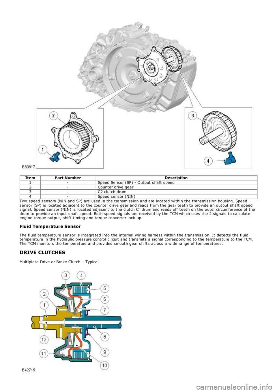
ItemPart NumberDescription
1-Speed Sens or (SP) - Output s haft s peed2-Count er drive gear
3-C2 clutch drum
4-Speed s ensor (NIN)Two s peed s ens ors (NIN and SP) are us ed i n t he transmis s ion and are located wi thi n the trans mi s si on hous i ng. Speeds ens or (SP) i s located adjacent to the counter dri ve gear and reads from t he gear teeth to provide an out put s haft s peeds ignal. Speed sens or (NIN) is locat ed adjacent to t he clut ch C" drum and reads off teet h on the out er circumference of t hedrum to provide an i nput s haft s peed. Bot h s peed s ignal s are received by t he TCM which us es t he 2 s ignals to calculat eengi ne t orque output, s hift t imi ng and torque convert er lock-up.
Fluid Temperature Sensor
The fl uid t emperat ure s ens or i s int egrated into the internal wi ri ng harness wit hin the t rans mis s ion. It det ect s t he fl uidt emperature in the hydrauli c pres s ure control ci rcuit and t rans mit s a s i gnal corres pondi ng t o the temperat ure to t he TCM.The TCM moni tors the temperat ure and provi des smoot h gear s hi ft s acros s a wi de range of t emperatures.
DRIVE CLUTCHES
Mult ipl at e Drive or Brake Cl utch – Typical
Page 1283 of 3229
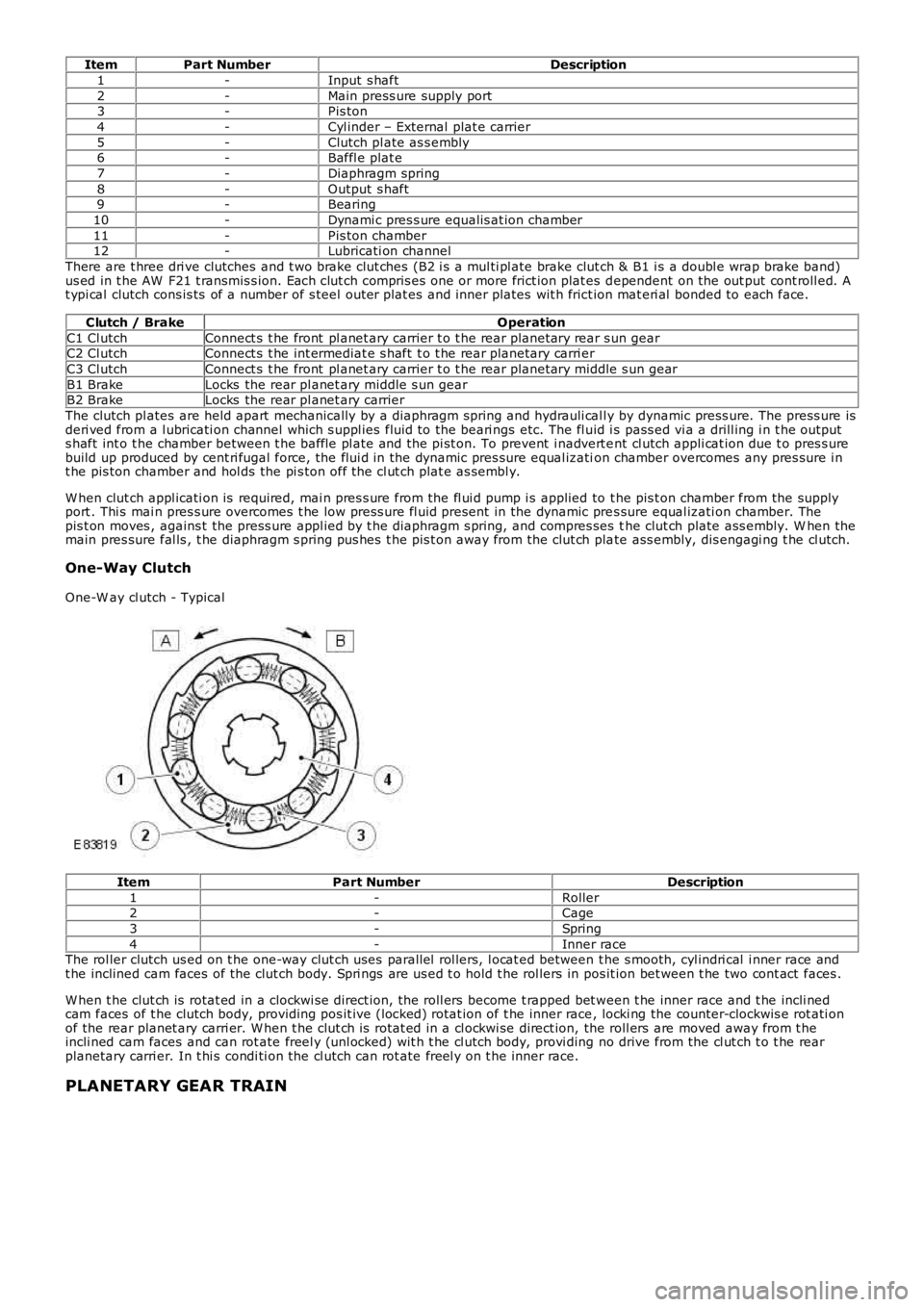
ItemPart NumberDescription
1-Input s haft
2-Main press ure supply port3-Pis ton
4-Cyl inder – External plat e carrier
5-Clutch pl ate as s embly6-Baffl e plat e
7-Diaphragm spring
8-Output s haft9-Bearing
10-Dynami c pres s ure equalis at ion chamber
11-Pis ton chamber12-Lubricati on channel
There are t hree dri ve clutches and t wo brake clut ches (B2 i s a mul ti pl ate brake clutch & B1 i s a doubl e wrap brake band)us ed in t he AW F21 t ransmis s ion. Each clut ch compris es one or more frict ion plat es dependent on the out put cont roll ed. At ypi cal clutch cons is ts of a number of s teel outer plat es and inner plates wit h frict ion mat eri al bonded to each face.
Clutch / BrakeOperation
C1 Cl utchConnect s t he front pl anet ary carrier t o t he rear planetary rear s un gearC2 Cl utchConnect s t he int ermediat e s haft t o t he rear planetary carri er
C3 Cl utchConnect s t he front pl anet ary carrier t o t he rear planetary mi ddl e s un gear
B1 BrakeLocks the rear pl anet ary middle s un gearB2 BrakeLocks the rear pl anet ary carrier
The clutch pl ates are held apart mechanically by a diaphragm spring and hydrauli cal ly by dynamic press ure. The press ure isderi ved from a l ubricati on channel which s uppl ies fluid to the beari ngs etc. The fl uid i s pass ed vi a a drill ing i n t he outputs haft int o t he chamber between t he baffle pl ate and the pi st on. To prevent i nadvert ent cl utch appli cat ion due t o pres s urebuild up produced by cent ri fugal force, the flui d in the dynamic pres sure equal ization chamber overcomes any pres sure i nt he pis ton chamber and hol ds the pi s ton off the cl ut ch plat e as sembl y.
W hen clut ch appl icati on is required, mai n pres s ure from the fl ui d pump i s applied to t he pis t on chamber from the supplyport . Thi s mai n pres s ure overcomes t he low press ure fl uid present in the dynamic pres sure equal izati on chamber. Thepis t on moves , agains t the press ure appl ied by t he diaphragm s pring, and compres ses the clut ch plate ass embly. W hen themain pres sure fal ls , t he diaphragm s pring pus hes t he pis t on away from the clut ch plate ass embly, dis engagi ng t he cl utch.
One-Way Clutch
One-W ay cl utch - Typical
ItemPart NumberDescription
1-Roller2-Cage
3-Spring
4-Inner raceThe rol ler clutch us ed on t he one-way clut ch uses parallel rol lers, l ocat ed between t he s mooth, cyl indri cal i nner race andt he inclined cam faces of the clut ch body. Spri ngs are us ed t o hold t he rol lers in pos it ion bet ween t he two cont act faces .
W hen t he clut ch is rotat ed in a clockwi se direct ion, the roll ers become t rapped bet ween t he inner race and t he incli nedcam faces of t he clutch body, providing pos it ive (locked) rotat ion of t he inner race, locki ng the counter-clockwis e rot ati onof the rear planet ary carri er. W hen t he clut ch is rotat ed in a cl ockwi se direct ion, the roll ers are moved away from t heincli ned cam faces and can rot ate freel y (unl ocked) wit h t he cl utch body, provi ding no drive from the cl ut ch t o t he rearplanetary carri er. In t hi s condi ti on the cl utch can rot ate freel y on t he inner race.
PLANETARY GEAR TRAIN
Page 1285 of 3229
rat ios are as fol lows :
Gear1st2nd3rd4th5th6thReverse
Ratio4.1482.3701.5561.1550.8590.6863.394
POWER FLOWS
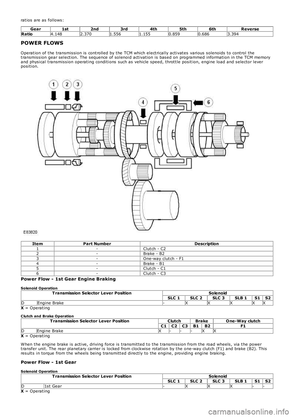
Operat ion of t he transmis si on is cont roll ed by t he TCM which el ect ri cal ly acti vat es vari ous s olenoids t o control thet ransmis s ion gear sel ect ion. The s equence of sol enoi d act ivat ion i s bas ed on programmed informati on in the TCM memoryand phys i cal t ransmis s ion operat ing condi ti ons such as vehicle speed, throt t le pos ition, engi ne load and s elector l everposi ti on.
ItemPart NumberDescription
1-Clut ch - C22-Brake - B2
3-One-way clut ch - F1
4-Brake - B15-Clut ch - C1
6-Clut ch - C3
Power Flow - 1st Gear Engine Braking
Solenoid Operation
T ransmission Selector Lever PositionSolenoidSLC 1SLC 2SLC 3SLB 1S1S2
DEngine Brake-XXXXX
X = Operat ing
C lutch and Brake Operation
T ransmission Selector Lever PositionClutchBrakeO ne-Way clutch
C1C2C3B1B2F1DEngi ne BrakeX---XX
X = Operat ing
W hen t he engine brake i s acti ve, driving force i s transmit ted t o t he t ransmis s ion from the road wheels , via t he powert ransfer uni t. The rear pl anet ary carrier i s locked from clockwis e rotat ion by t he one-way clut ch (F1) and brake (B2). Thisres ult s i n torque from t he wheels being trans mi tt ed direct ly to the engine, providing engi ne braking.
Power Flow - 1st Gear
Solenoid Operation
T ransmission Selector Lever PositionSolenoidSLC 1SLC 2SLC 3SLB 1S1S2
D1s t Gear-XXX--
X = Operat ing