2006 INFINITI M35 ipdm relays
[x] Cancel search: ipdm relaysPage 189 of 5621

AT-110
DTC P0615 START SIGNAL CIRCUIT
Revision: 2006 January2006 M35/M45
TCM terminals and data are reference value. Measured between each terminal and ground.
Diagnostic ProcedureNCS001KV
1. CHECK STARTER RELAY
With CONSULT-II
1. Turn ignition switch ON. (Do not start engine.)
2. Select “SELECTION FROM MENU” in “DATA MONITOR” mode
for “A/T” with CONSULT-II and check monitor “STARTER
RELAY” ON/OFF.
Without CONSULT-II
1. Turn ignition switch ON. (Do not start engine.)
2. Check voltage between the IPDM E/R connector and ground.
OK or NG
OK >> GO TO 5.
NG >> GO TO 2.
2. CHECK HARNESS BETWEEN A/T ASSEMBLY HARNESS CONNECTOR AND IPDM E/R CONNEC-
TOR
1. Turn ignition switch OFF.
2. Disconnect A/T assembly harness connector and IPDM E/R connector.
3. Check continuity between A/T assembly harness connector and
IPDM E/R connector.
4. If OK, check harness for short to ground and short to power.
5. Reinstall any part removed.
OK or NG
OK >> GO TO 3.
NG >> Repair open circuit or short to ground or short to power in harness or connectors.
Terminal Item Condition Data (Approx.)
9 Starter relaySelector lever in “N”, “P” positions. Battery voltage
Selector lever in “R”, “D” positions. 0V
Item name Condition Display value
STARTER RELAYSelector lever in “N”, “P” positions. ON
Selector lever in “R”, “D” positions. OFF
Item Connector Terminal Shift position Voltage (Approx.)
Starter
relayE9 53 Ground“N”, “P” Battery voltage
“R”, “D” 0V
PCIA0056E
SCIA2103E
Item Connector Terminal Continuity
A/T assembly harness con-
nectorF42 9
Ye s
IPDM E/R connector E9 53
SCIA5439E
Page 1087 of 5621

BL-148
INTELLIGENT KEY SYSTEM/ENGINE START FUNCTION
Revision: 2006 January2006 M35/M45
Terminals and Reference Value for PDUNIS001YI
Te r -
minal
No.Wire
colorItemCondition
Voltage (V)
(Approx.) Push-
button
ignition
switch
positionOperation or conditions
1 P Wake up signalLOCKSleep condition (30 seconds or more
after all doors are closed under the con-
dition that the power supply position is in
the LOCK position)Battery voltage
— Wake-up condition (Open driver door) 0
2 G Starter control signalON At starter motor cranking 0
— Any condition other than above Battery voltage
3GRSteering lock unit
power sourceLOCKPush-button ignition switch is pressed
under the condition that Intelligent Key is
in the vehicle or Intelligent Key is inserted0
Battery voltage 0
— Any condition other than above 0
6VSteering lock control
signal-1—Push-button ignition switch is pressed
under the condition that Intelligent Key is
in the vehicle or Intelligent Key is insertedBattery voltage
LOCKPower supply position is in LOCK posi-
tion
(Steering lock activated)Battery voltage
0 Battery volt-
age
(Battery voltage is detected when
activating the steering lock)
7LGSteering lock control
signal-2—Push-button ignition switch is pressed
under the condition that Intelligent Key is
in the vehicle or Intelligent Key is insertedBattery voltage
LOCKPower supply position is in LOCK posi-
tion
(Steering lock activated)Battery voltage
0 Battery volt-
age
(Battery voltage is detected when
activating the steering lock)
9OSteering lock feed
back signal— Steering lock: Lock 0
LOCK Steering lock: Unlock 8
10 B Ground — — 0
11 YIPDM E/R current sig-
nalSTART At starter motor cranking 5
LOCK Any condition other than above 2
12 R Feed back signalLOCKSleep condition (30 seconds or more
after all doors are closed under the con-
dition that the power supply position is in
the LOCK position)1
—Wake-up condition (any condition other
than above)0
13 R Starter relaySTART At starter motor cranking Battery voltage
— Any condition other than above 4
14 SB Power source (fuse) — — Battery voltage
15 LPower source (fusible
link)— — Battery voltage
17 GPower source (fusible
link)— — Battery voltage
Page 1114 of 5621
INTELLIGENT KEY SYSTEM/ENGINE START FUNCTION
BL-175
C
D
E
F
G
H
J
K
L
MA
B
BL
Revision: 2006 January2006 M35/M45
TERMINALS AND REFERENCE VALUE
Intelligent Key Unit
PDU (Power Distribution Unit)
SELF-DIAGNOSTIC LOGIC
DIAGNOSTIC PROCEDURE
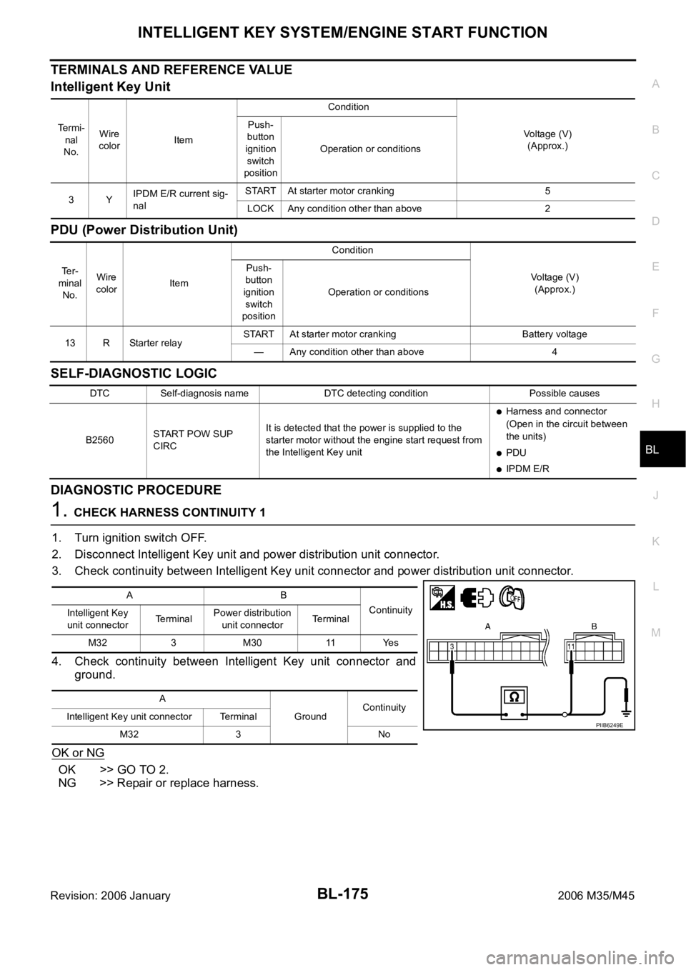
1. CHECK HARNESS CONTINUITY 1
1. Turn ignition switch OFF.
2. Disconnect Intelligent Key unit and power distribution unit connector.
3. Check continuity between Intelligent Key unit connector and power distribution unit connector.
4. Check continuity between Intelligent Key unit connector and
ground.
OK or NG
OK >> GO TO 2.
NG >> Repair or replace harness.
Te r m i -
nal
No.Wire
colorItemCondition
Voltage (V)
(Approx.) Push-
button
ignition
switch
positionOperation or conditions
3YIPDM E/R current sig-
nalSTART At starter motor cranking 5
LOCK Any condition other than above 2
Te r -
minal
No.Wire
colorItemCondition
Voltage (V)
(Approx.) Push-
button
ignition
switch
positionOperation or conditions
13 R Starter relaySTART At starter motor cranking Battery voltage
— Any condition other than above 4
DTC Self-diagnosis name DTC detecting condition Possible causes
B2560START POW SUP
CIRCIt is detected that the power is supplied to the
starter motor without the engine start request from
the Intelligent Key unit
Harness and connector
(Open in the circuit between
the units)
PDU
IPDM E/R
AB
Continuity
Intelligent Key
unit connectorTerminalPower distribution
unit connectorTerminal
M32 3 M30 11 Yes
A
GroundContinuity
Intelligent Key unit connector Terminal
M32 3 No
PIIB6249E
Page 1207 of 5621

BL-268
IVIS (INFINITI VEHICLE IMMOBILIZER SYSTEM-NATS)
Revision: 2006 January2006 M35/M45
CONSULT-IINIS0020N
CONSULT-II INSPECTION PROCEDURE
1. Turn ignition switch OFF.
2. Insert IVIS (NATS) program card into CONSULT-II.
3. Connect CONSULT-II and CONSULT-II CONVERTER to data
link connector (1).
6VSteering lock control
signal-1—Push-button ignition switch is pressed
under the condition that Intelligent Key is
in the vehicle or Intelligent Key is insertedBattery voltage
LOCKPower supply position is in LOCK posi-
tion
(Steering lock activated)Battery voltage 0 Battery volt-
age
(Battery voltage is detected when
activating the steering lock)
7LGSteering lock control
signal-2—Push-button ignition switch is pressed
under the condition that Intelligent Key is
in the vehicle or Intelligent Key is insertedBattery voltage
LOCKPower supply position is in LOCK posi-
tion
(Steering lock activated)Battery voltage
0 Battery volt-
age
(Battery voltage is detected when
activating the steering lock)
9OSteering lock feed
back signal—Power supply position is in ACC or ON
position0
LOCKPower supply position is in LOCK posi-
tion0
8 0
(0V is detected when activating the
steering lock)
10 B Ground — — 0
11 YIPDM E/R current sig-
nalSTART At starter motor cranking 5
LOCK Any condition other than above 2
12 R Feed back signalLOCKSleep condition (30 seconds or more
after all doors are closed under the con-
dition that the power supply position is in
the LOCK position)1
—Wake-up condition (any condition other
than above)0
13 R Starter relaySTART At starter motor cranking Battery voltage
— Any condition other than above 4
14 SB Power source (fuse) — — Battery voltage
15 LPower source (fusible
link)— — Battery voltage
17 GPower source (fusible
link)— — Battery voltage Te r -
minal
No.Wire
colorItemCondition
Voltage (V)
(Approx.) Push-
button
ignition
switch
positionOperation or conditions
Program card : NATS (AEN04D)
PBIB2712E
Page 4435 of 5621
LT-8
HEADLAMP (FOR USA) - CONVENTIONAL TYPE -
Revision: 2006 January2006 M35/M45
HEADLAMP (FOR USA) - CONVENTIONAL TYPE -PFP:26010
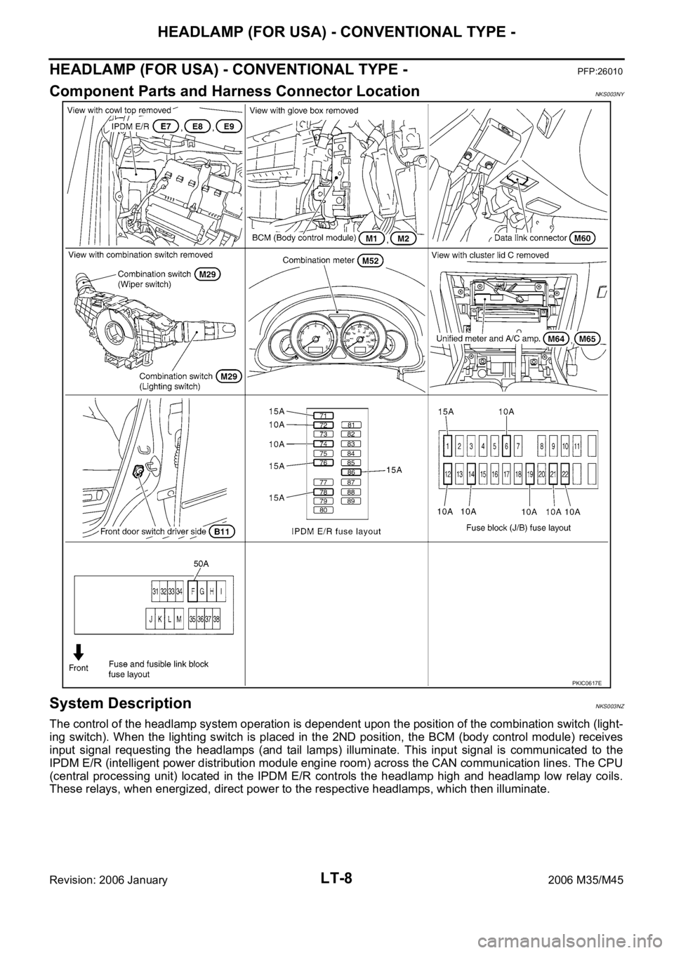
Component Parts and Harness Connector LocationNKS003NY
System DescriptionNKS003NZ
The control of the headlamp system operation is dependent upon the position of the combination switch (light-
ing switch). When the lighting switch is placed in the 2ND position, the BCM (body control module) receives
input signal requesting the headlamps (and tail lamps) illuminate. This input signal is communicated to the
IPDM E/R (intelligent power distribution module engine room) across the CAN communication lines. The CPU
(central processing unit) located in the IPDM E/R controls the headlamp high and headlamp low relay coils.
These relays, when energized, direct power to the respective headlamps, which then illuminate.
PKIC0617E
Page 4470 of 5621
HEADLAMP (FOR USA) - XENON TYPE -
LT-43
C
D
E
F
G
H
I
J
L
MA
B
LT
Revision: 2006 January2006 M35/M45
HEADLAMP (FOR USA) - XENON TYPE -PFP:26010
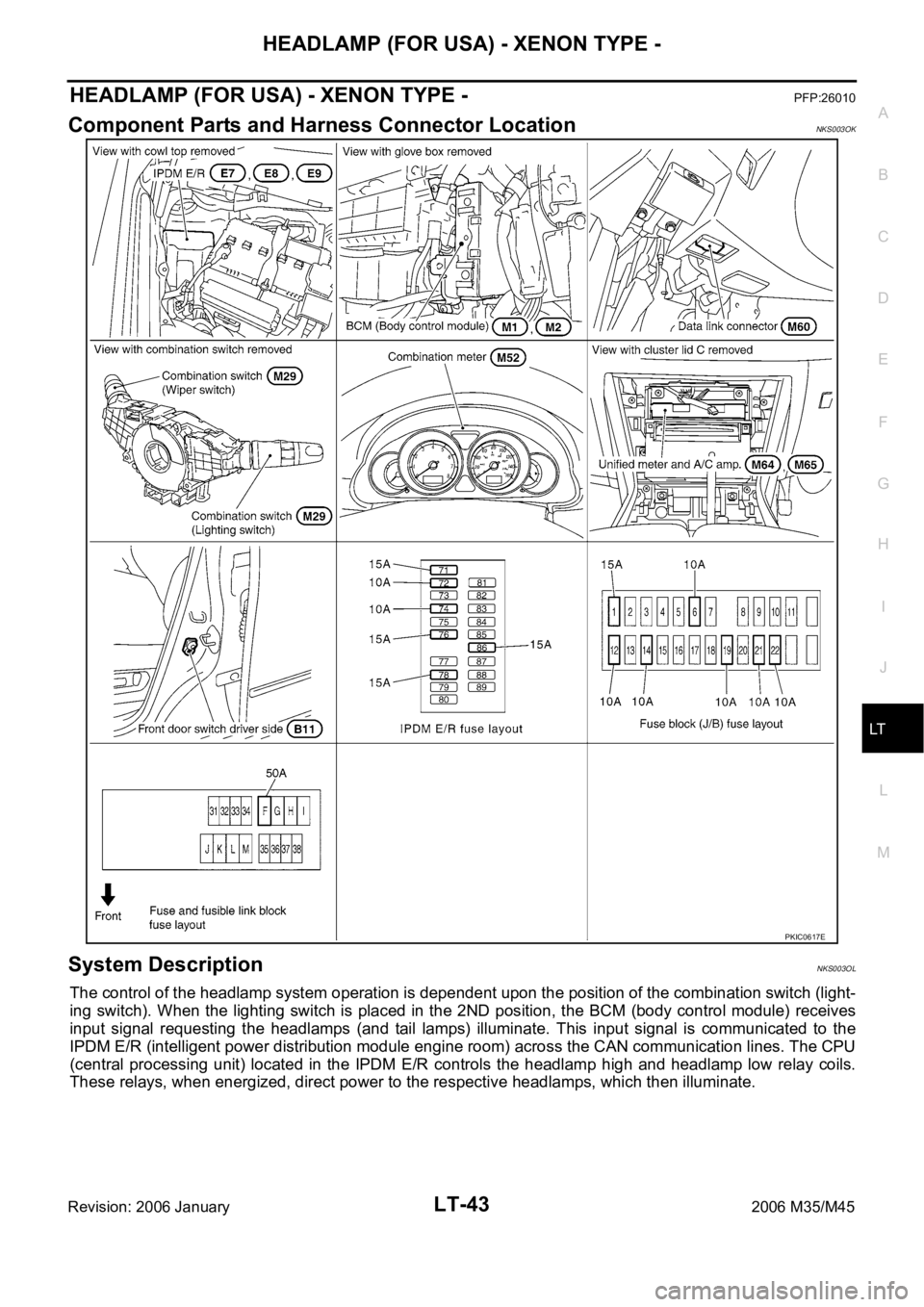
Component Parts and Harness Connector LocationNKS003OK
System DescriptionNKS003OL
The control of the headlamp system operation is dependent upon the position of the combination switch (light-
ing switch). When the lighting switch is placed in the 2ND position, the BCM (body control module) receives
input signal requesting the headlamps (and tail lamps) illuminate. This input signal is communicated to the
IPDM E/R (intelligent power distribution module engine room) across the CAN communication lines. The CPU
(central processing unit) located in the IPDM E/R controls the headlamp high and headlamp low relay coils.
These relays, when energized, direct power to the respective headlamps, which then illuminate.
PKIC0617E
Page 4845 of 5621

PG-18
IPDM E/R (INTELLIGENT POWER DISTRIBUTION MODULE ENGINE ROOM)
Revision: 2006 January2006 M35/M45
IPDM E/R (INTELLIGENT POWER DISTRIBUTION MODULE ENGINE ROOM)
PFP:284B7
System DescriptionNKS004E2
IPDM E/R (Intelligent Power Distribution Module Engine Room) integrates the relay box and fuse block
which were originally placed in engine compartment. It controls integrated relay via IPDM E/R control cir-
cuit.
IPDM E/R-integrated control circuit performs ON-OFF operation of relay, CAN communication control and
oil pressure switch signal reception, etc.
It controls operation of each electrical part via ECM, BCM and CAN communication lines.
CAUTION:
None of the IPDM E/R-integrated relays can be removed.
SYSTEMS CONTROLLED BY IPDM E/R
1. Lamp control
Using CAN communication, it receives signal from BCM and controls the following lamps:
Headlamps (HI, LO)
Tail, parking and license plate lamps
Front fog lamps
2. Daytime light relay control (for Canada models)
Using CAN communication, it receives signals from BCM and controls the daytime light relay.
3. Wiper control
Using CAN communication, it receives signals from BCM and controls the front wipers.
4. Rear window defogger relay control
Using CAN communication, it receives signals from BCM and controls the rear window defogger relay.
5. A/C compressor control
Using CAN communication, it receives signals from ECM and controls the A/C relay.
6. Cooling fan control
Using CAN communication, it receives signals from ECM and controls cooling fan via cooling fan control
module.
7. Horn control
Using CAN communication, it receives signals from BCM and controls horn relay.
8. Starter motor relay control
Using CAN communication, it receives signals from BCM and controls starter motor relay.
9. Alternator control
Using CAN communication, it receives signal from ECM and controls power generation voltage.
CAN COMMUNICATION LINE CONTROL
With CAN communication, by connecting each control unit using two communication lines (CAN L-line, CAN
H-line), it is possible to transmit maximum amount of information with minimum wiring. Each control unit can
transmit and receive data, and reads necessary information only.
1. Fail-safe control
When CAN communication with other control units is impossible, IPDM E/R performs fail-safe control.
After CAN communication recovers normally, it also returns to normal control.
Operation of control parts by IPDM E/R during fail-safe mode is as follows:
Controlled system Fail-safe mode
Headlamps
With the ignition switch ON, the headlamp low relay is ON.
With the ignition switch OFF, the headlamp low relay is OFF.
Tail, parking and
license plate lamps
With the ignition switch ON, the tail lamp relay is ON.
With the ignition switch OFF, the tail lamp relay is OFF.
Cooling fan
With the ignition switch ON, the cooling fan HI operates.
With the ignition switch OFF, the cooling fan stops.
Front wiperUntil the ignition switch is turned off, the front wiper LO and HI remains in the same status it was in just
before fail
safe control was initiated.
Page 5571 of 5621
WW-4
FRONT WIPER AND WASHER SYSTEM
Revision: 2006 January2006 M35/M45
FRONT WIPER AND WASHER SYSTEMPFP:28810
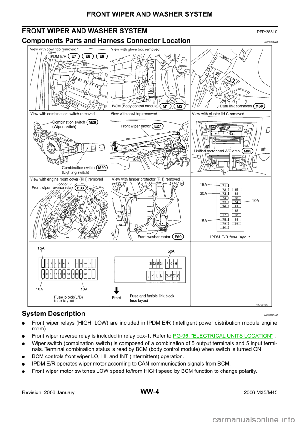
Components Parts and Harness Connector LocationNKS003WB
System DescriptionNKS003WC
Front wiper relays (HIGH, LOW) are included in IPDM E/R (intelligent power distribution module engine
room).
Front wiper reverse relay is included in relay box-1. Refer to PG-96, "ELECTRICAL UNITS LOCATION" .
Wiper switch (combination switch) is composed of a combination of 5 output terminals and 5 input termi-
nals. Terminal combination status is read by BCM (body control module) when switch is turned ON.
BCM controls front wiper LO, HI, and INT (intermittent) operation.
IPDM E/R operates wiper motor according to CAN communication signals from BCM.
Front wiper motor switches LOW speed to/from HIGH speed by BCM function to change polarity.
PKIC0616E