2006 INFINITI M35 diagram
[x] Cancel search: diagramPage 5148 of 5621
STARTING SYSTEM
SC-11
C
D
E
F
G
H
I
J
L
MA
B
SC
Revision: 2006 January2006 M35/M45
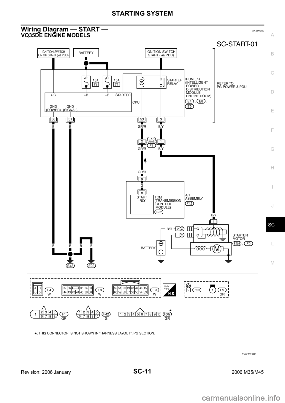
Wiring Diagram — START — NKS003NJ
VQ35DE ENGINE MODELS
TKWT3232E
Page 5162 of 5621
CHARGING SYSTEM
SC-25
C
D
E
F
G
H
I
J
L
MA
B
SC
Revision: 2006 January2006 M35/M45
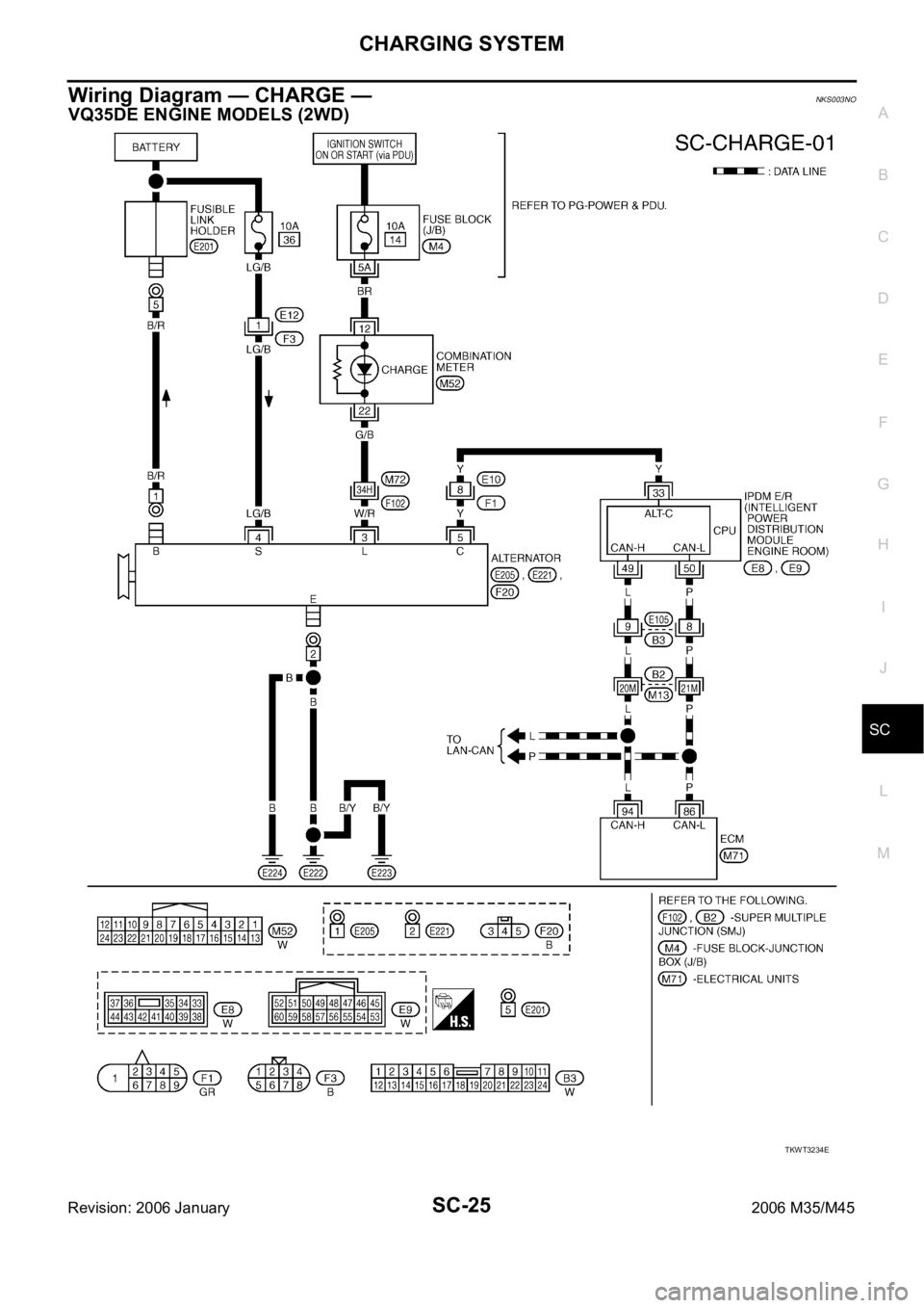
Wiring Diagram — CHARGE — NKS003NO
VQ35DE ENGINE MODELS (2WD)
TKWT3234E
Page 5182 of 5621
SE-1
SEAT
I BODY
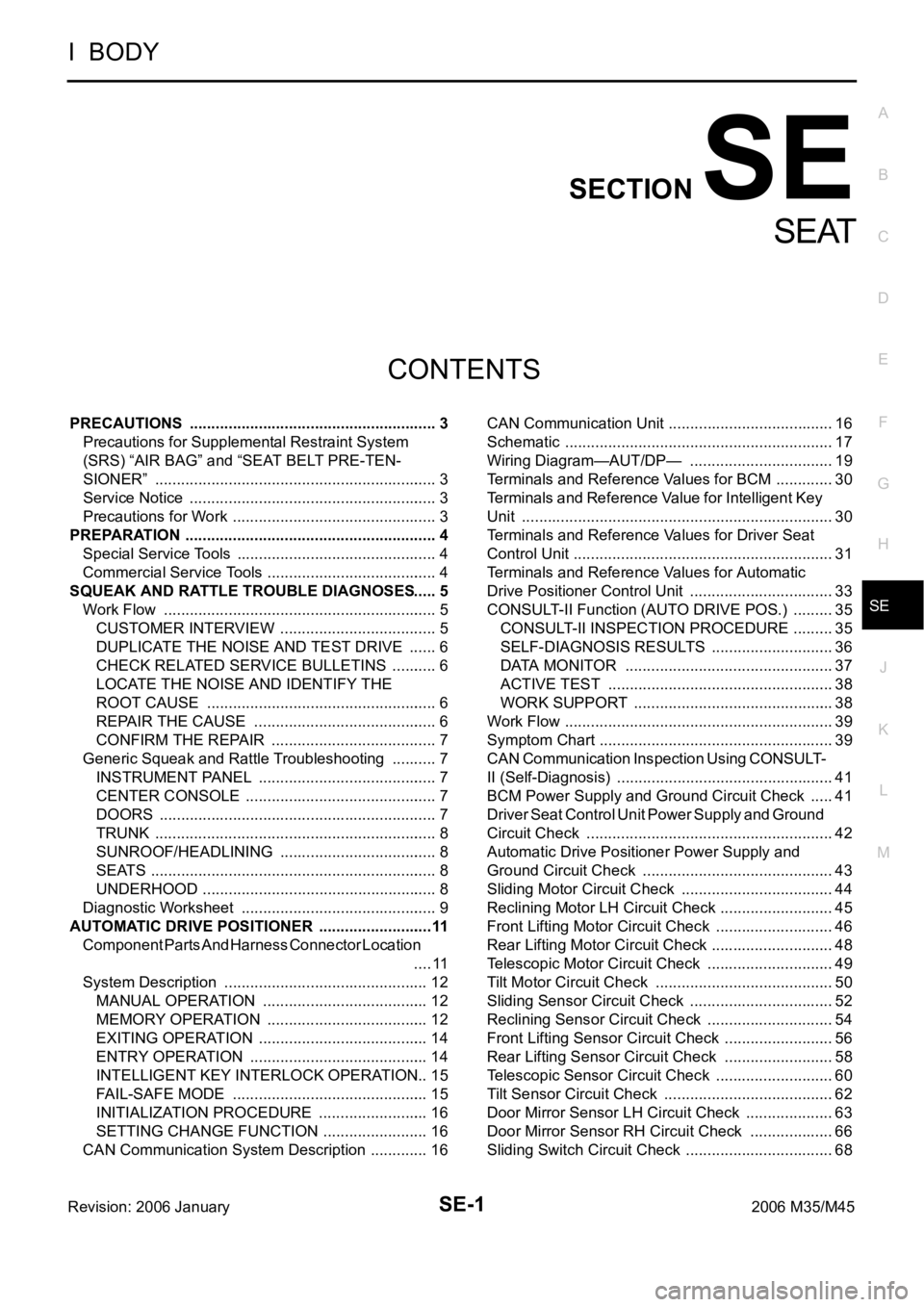
CONTENTS
C
D
E
F
G
H
J
K
L
M
SECTION SE
A
B
SE
Revision: 2006 January2006 M35/M45
SEAT
PRECAUTIONS .......................................................... 3
Precautions for Supplemental Restraint System
(SRS) “AIR BAG” and “SEAT BELT PRE-TEN-
SIONER” .................................................................. 3
Service Notice .......................................................... 3
Precautions for Work ...........................................
..... 3
PREPARATION ........................................................... 4
Special Service Tools ............................................... 4
Commercial Service Tools ........................................ 4
SQUEAK AND RATTLE TROUBLE DIAGNOSES ..... 5
Work Flow ................................................................ 5
CUSTOMER INTERVIEW ..................................... 5
DUPLICATE THE NOISE AND TEST DRIVE ....... 6
CHECK RELATED SERVICE BULLETINS ........... 6
LOCATE THE NOISE AND IDENTIFY THE
ROOT CAUSE ...................................................... 6
REPAIR THE CAUSE ........................................... 6
CONFIRM THE REPAIR ....................................... 7
Generic Squeak and Rattle Troubleshooting ........... 7
INSTRUMENT PANEL .......................................... 7
CENTER CONSOLE ............................................. 7
DOORS ................................................................. 7
TRUNK .................................................................. 8
SUNROOF/HEADLINING ..................................... 8
SEATS ................................................................... 8
UNDERHOOD ....................................................... 8
Diagnostic Worksheet .............................................. 9
AUTOMATIC DRIVE POSITIONER ...........................11
Component Parts And Harness Connector Location
.... 11
System Description ................................................ 12
MANUAL OPERATION ....................................... 12
MEMORY OPERATION ...................................... 12
EXITING OPERATION ........................................ 14
ENTRY OPERATION .......................................... 14
INTELLIGENT KEY INTERLOCK OPERATION ... 15
FAIL-SAFE MODE .............................................. 15
INITIALIZATION PROCEDURE .......................... 16
SETTING CHANGE FUNCTION ......................... 16
CAN Communication System Description .............. 16CAN Communication Unit ....................................... 16
Schematic ............................................................... 17
Wiring Diagram—AUT/DP— .................................. 19
Terminals and Reference Values for BCM .............. 30
Terminals and Reference Value for Intelligent Key
Unit ......................................................................... 30
Terminals and Reference Values for Driver Seat
Control Unit ............................................................. 31
Terminals and Reference Values for Automatic
Drive Positioner Control Unit .................................. 33
CONSULT-II Function (AUTO DRIVE POS.) .......... 35
CONSULT-II INSPECTION PROCEDURE .......... 35
SELF-DIAGNOSIS RESULTS ............................. 36
DATA MONITOR ................................................. 37
ACTIVE TEST ..................................................... 38
WORK SUPPORT ............................................... 38
Work Flow ............................................................... 39
Symptom Chart ....................................................... 39
CAN Communication Inspection Using CONSULT-
II (Self-Diagnosis) ................................................... 41
BCM Power Supply and Ground Circuit Check ...... 41
Driver Seat Control Unit Power Supply and Ground
Circuit Check .......................................................... 42
Automatic Drive Positioner Power Supply and
Ground Circuit Check ............................................. 43
Sliding Motor Circuit Check .................................... 44
Reclining Motor LH Circuit Check ........................... 45
Front Lifting Motor Circuit Check ............................ 46
Rear Lifting Motor Circuit Check ............................. 48
Telescopic Motor Circuit Check .............................. 49
Tilt Motor Circuit Check .......................................
... 50
Sliding Sensor Circuit Check .................................. 52
Reclining Sensor Circuit Check .............................. 54
Front Lifting Sensor Circuit Check .......................... 56
Rear Lifting Sensor Circuit Check .......................... 58
Telescopic Sensor Circuit Check ............................ 60
Tilt Sensor Circuit Check ........................................ 62
Door Mirror Sensor LH Circuit Check ..................... 63
Door Mirror Sensor RH Circuit Check .................... 66
Sliding Switch Circuit Check ................................... 68
Page 5183 of 5621

SE-2Revision: 2006 January2006 M35/M45 Reclining Switch Circuit Check ............................... 70
Lifting Switch (Front) Circuit Check ........................ 72
Lifting Switch (Rear) Circuit Check ......................... 74
Power Seat Switch Ground Circuit Check .............. 75
Telescopic Switch Circuit Check ............................. 76
Tilt Switch Circuit Check ......................................
... 78
Seat Memory and Set Switch Circuit Check ........... 80
Seat Memory Indicator Lamp Circuit Check ........... 81
Door Mirror Sensor Power Supply and Ground Cir-
cuit Check ............................................................... 83
A/T Device (Detention Switch) Circuit Check ......... 85
Front Door Switch (Driver Side) Circuit Check ....... 86
UART Communication Line Circuit Check .............. 87
Lumber Support Circuit Check ............................... 89
POWER SEAT(PASSENGER SIDE) ......................... 91
Component Parts and Harness Connector Location ... 91
Wiring Diagram—SEAT—/Passenger Side ............ 92
Terminals and Reference Values for BCM .............. 94
POWER SEAT(REAR) .............................................. 95
Component Parts and Harness Connector Location ... 95
System Description ................................................. 95
REAR POWER SEAT LH AND RH OPERATION ... 95
REAR SEAT RETREAT FUNCTION ................... 96
Schematic ............................................................... 97
Wiring Diagram—R/SEAT— ................................... 98
Terminals and Reference Values for Rear Seat Con-
trol Unit .................................................................102
Work Flow .............................................................103
Trouble Diagnoses Symptom Chart ......................103
Rear Power Seat Power Supply Circuit Inspection .103
Rear Seat Control Unit Power Supply and Ground
Circuit Inspection ..................................................104
Rear Seat Sliding Motor Circuit Inspection ...........105
Rear Power Seat Switch Circuit Inspection ..........106
Automatic Return Cancel Switch Circuit Inspection .108
Automatic Return Cancel Switch Inspection .........109
Rear Door Switch Circuit Inspection .....................110
Rear Seat Sliding Sensor Circuit Inspection ..........111
CLIMATE CONTROLLED SEAT .............................113
Component Parts and Harness Connector Location .113
System Description ...............................................113
Schematic .............................................................117
Wiring Diagram—C/SEAT— .................................118
Terminal and Reference Value for Climate Con-
trolled Seat Control Unit ......................................
.123
Work Flow .............................................................124
Preliminary Check ................................................124
Trouble Diagnoses Symptom Chart .....................
.125
Climate Controlled Seat Control Unit Power Supply
Circuit Check ........................................................126
Climate Controlled Seat Control Unit Power Supply
and Ground Circuit Inspection ..............................127
Climate Controlled Seat Switch Power Supply Cir-cuit Inspection .......................................................130
Climate Controlled Seat Switch Circuit Inspection .131
Climate Controlled Seat Switch Indicator Circuit
Inspection ..............................................................133
Seat Cushion Thermal Electric Device Circuit
Inspection ..............................................................135
Seatback Thermal Electric Device Circuit Inspec-
tion ........................................................................136
Seat Cushion Thermal Electric Device Sensor Cir-
cuit Inspection .......................................................137
Seatback Thermal Electric Device Sensor Circuit
Inspection ..............................................................139
Climate Controlled Seat Blower Motor Circuit
Inspection ..............................................................140
Climate Controlled Seat Control Unit Inspection ...142
HEATED SEAT ........................................................143
Component Parts and Harness Connector Location .143
System Description ...............................................143
Schematic .............................................................145
Wiring Diagram —HSEAT— .................................146
Terminals and Reference Values for Rear Seat Con-
trol Unit ..................................................................151
Work Flow .............................................................151
Trouble Diagnoses Symptom Chart ......................151
Rear Heated Seat Power Supply and Ground Circuit
Inspection ..............................................................152
Rear Seat Control Unit Power Supply and Ground
Circuit Inspection ..................................................153
Rear Heated Seat Switch Circuit Inspection .........155
Rear Heated Seat Indicator Power Supply Circuit
Inspection ..............................................................157
Rear Heated Seat Indicator Circuit Inspection ......158
Rear Heated Seat Circuit Inspection .....................160
Rear Seatback Heater Circuit Inspection ..............161
FRONT SEAT ..........................................................163
Driver's Seat Components ....................................163
Passenger's Seat Components .............................165
Removal and Installation .......................................167
REMOVAL ..........................................................167
INSTALLATION ..................................................167
Disassembly and Assembly ..................................168
SEATBACK ........................................................168
SEAT CUSHION ................................................169
CLIMATE CONTROLLED SEAT ........................171
REAR SEAT .............................................................172
Bench Seat Components ......................................172
Power Seat (Split Type) Components ...................174Removal and Installation .......................................176
BENCH SEAT ....................................................176
POWER SEAT ...................................................176
Disassembly and Assembly ..................................177
BENCH SEAT ....................................................177
POWER SEAT ...................................................179
Page 5200 of 5621
AUTOMATIC DRIVE POSITIONER
SE-19
C
D
E
F
G
H
J
K
L
MA
B
SE
Revision: 2006 January2006 M35/M45
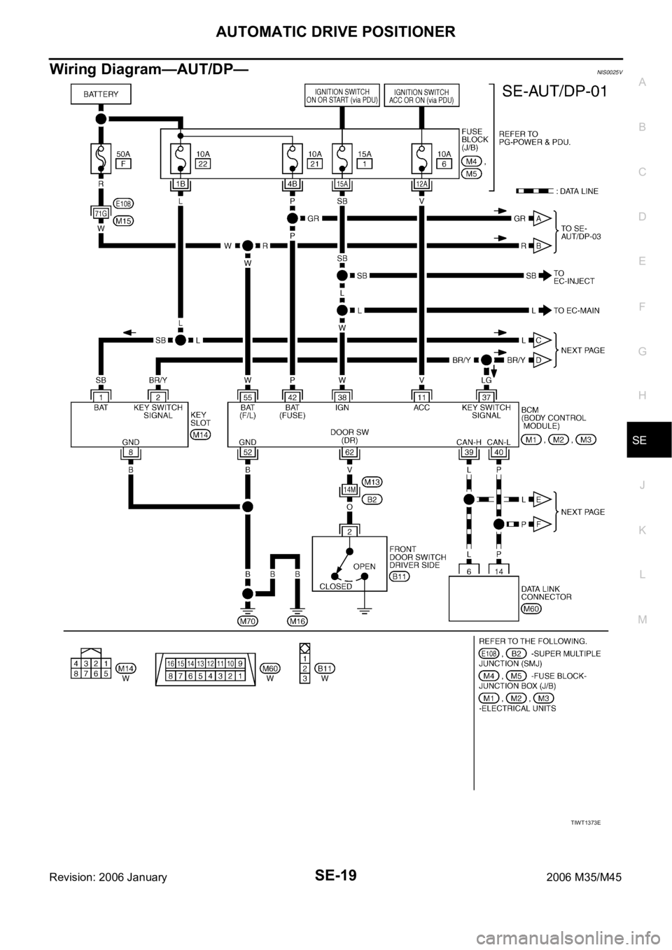
Wiring Diagram—AUT/DP—NIS0025V
TIWT1373E
Page 5273 of 5621
SE-92
POWER SEAT(PASSENGER SIDE)
Revision: 2006 January2006 M35/M45
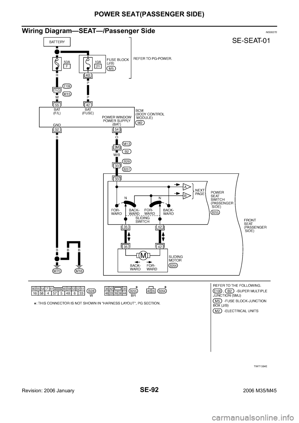
Wiring Diagram—SEAT—/Passenger SideNIS00270
TIWT1384E
Page 5279 of 5621
SE-98
POWER SEAT(REAR)
Revision: 2006 January2006 M35/M45
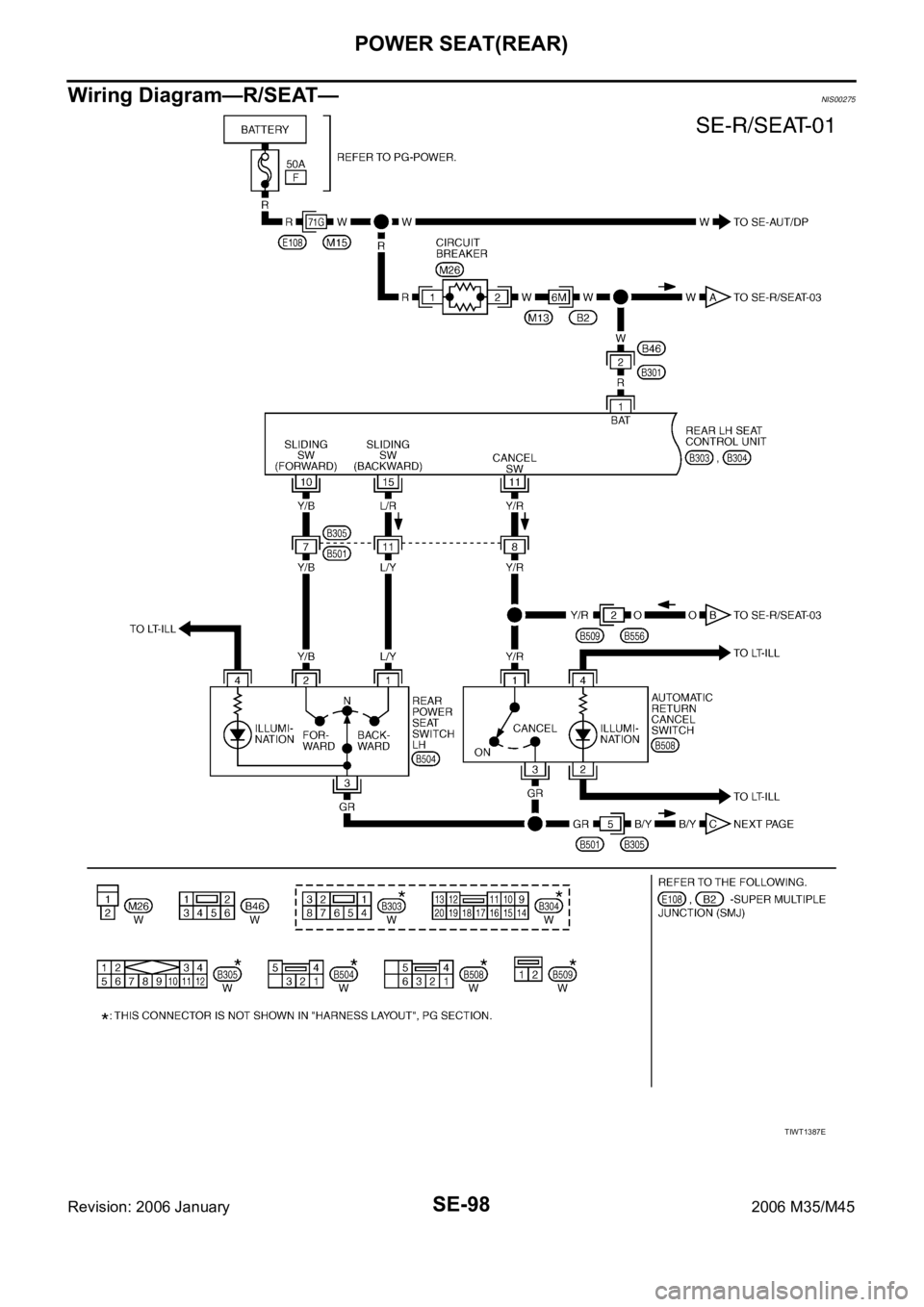
Wiring Diagram—R/SEAT—NIS00275
TIWT1387E
Page 5299 of 5621
SE-118
CLIMATE CONTROLLED SEAT
Revision: 2006 January2006 M35/M45
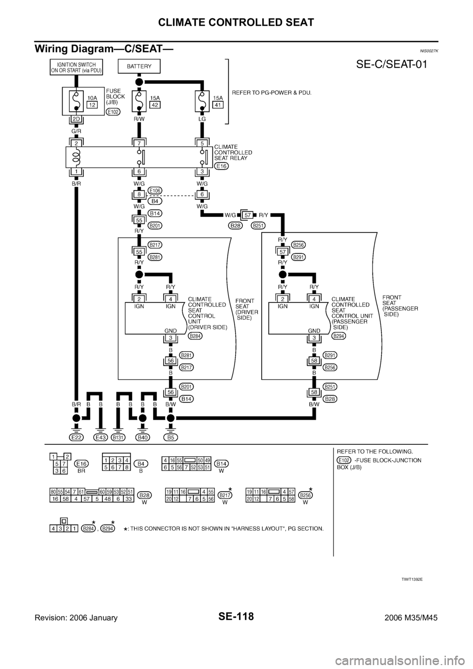
Wiring Diagram—C/SEAT— NIS0027K
TIWT1392E