2006 INFINITI M35 wiring
[x] Cancel search: wiringPage 3538 of 5621
POWER WINDOW SYSTEM
GW-19
C
D
E
F
G
H
J
K
L
MA
B
GW
Revision: 2006 January2006 M35/M45
CAN Communication System DescriptionNIS0021H
CAN (Controller Area Network) is a serial communication line for real time application. It is an on-vehicle mul-
tiplex communication line with high data communication speed and excellent error detection ability. Many elec-
tronic control units are equipped onto a vehicle, and each control unit shares information and links with other
control units during operation (not independent). In CAN communication, control units are connected with 2
communication lines (CAN H line, CAN L line) allowing a high rate of information transmission with less wiring.
Each control unit transmits/receives data but selectively reads required data only.
CAN Communication UnitNIS0021I
Refer to LAN-34, "CAN Communication Unit" .
Page 3540 of 5621
POWER WINDOW SYSTEM
GW-21
C
D
E
F
G
H
J
K
L
MA
B
GW
Revision: 2006 January2006 M35/M45
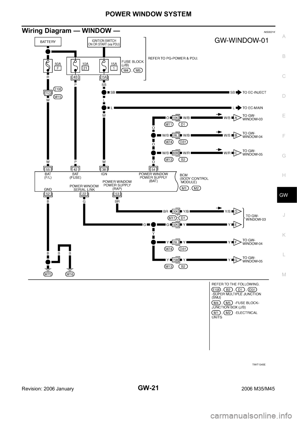
Wiring Diagram — WINDOW —NIS0021K
TIWT1345E
Page 3590 of 5621
INSIDE MIRROR
GW-71
C
D
E
F
G
H
J
K
L
MA
B
GW
Revision: 2006 January2006 M35/M45
INSIDE MIRRORPFP:96321
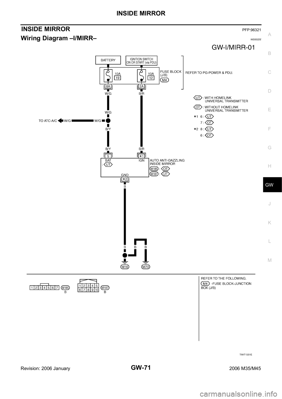
Wiring Diagram –I/MIRR–NIS0022E
TIWT1351E
Page 3594 of 5621
REAR WINDOW DEFOGGER
GW-75
C
D
E
F
G
H
J
K
L
MA
B
GW
Revision: 2006 January2006 M35/M45
With power and ground supplied, door mirror defogger filaments heat and defog the mirror.
CAN Communication System DescriptionNIS0022I
CAN (Controller Area Network) is a serial communication line for real time application. It is an on-vehicle mul-
tiplex communication line with high data communication speed and excellent error detection ability. Many elec-
tronic control units are equipped onto a vehicle, and each control unit shares information and links with other
control units during operation (not independent). In CAN communication, control units are connected with 2
communication lines (CAN H line, CAN L line) allowing a high rate of information transmission with less wiring.
Each control unit transmits/receives data but selectively reads required data only.
CAN Communication UnitNIS0022J
Refer to LAN-34, "CAN Communication Unit" .
Page 3596 of 5621
REAR WINDOW DEFOGGER
GW-77
C
D
E
F
G
H
J
K
L
MA
B
GW
Revision: 2006 January2006 M35/M45
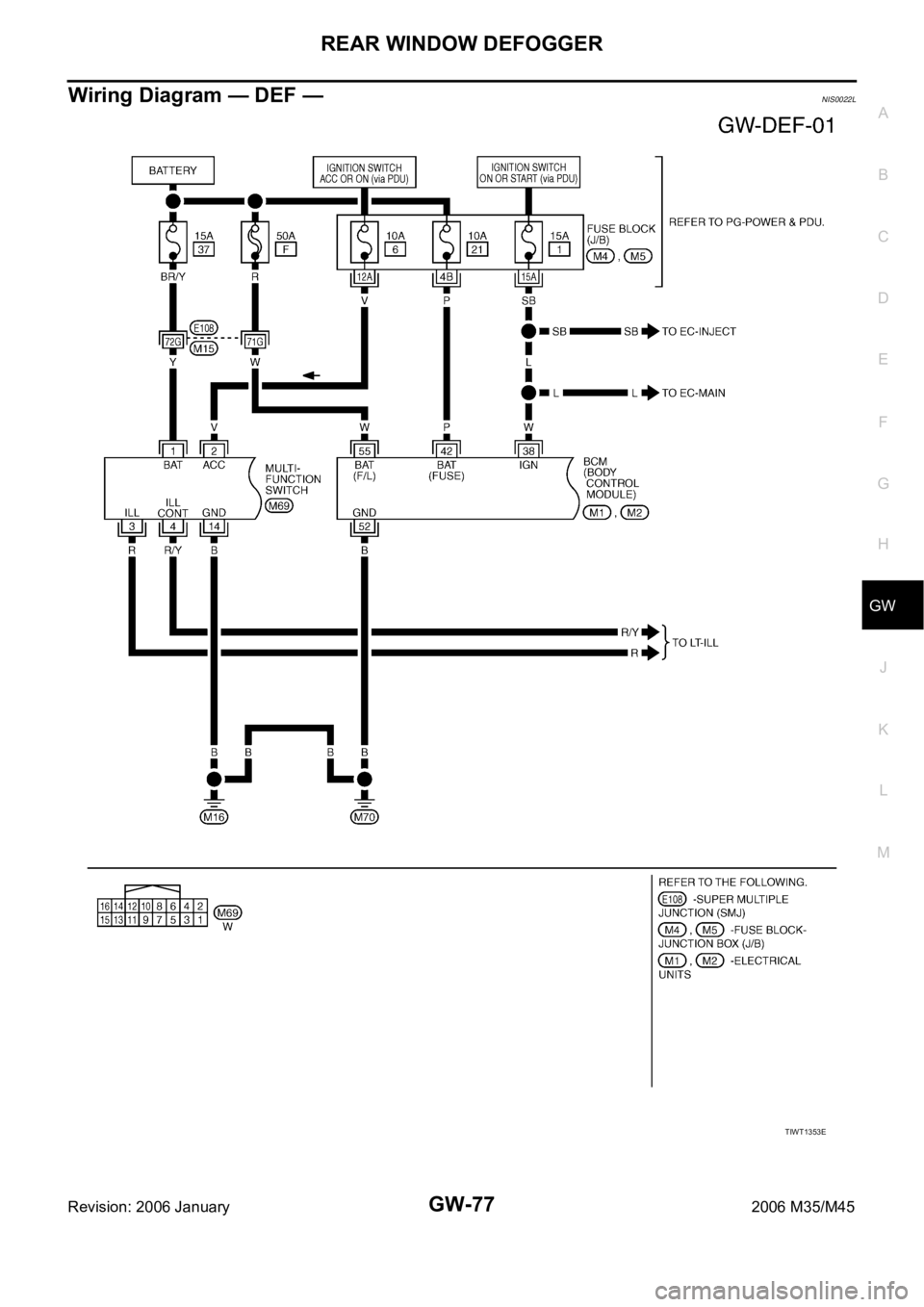
Wiring Diagram — DEF — NIS0022L
TIWT1353E
Page 3616 of 5621
![INFINITI M35 2006 Factory Service Manual REVERSE INTERLOCK DOOR MIRROR SYSTEM
GW-97
C
D
E
F
G
H
J
K
L
MA
B
GW
Revision: 2006 January2006 M35/M45
through 10A fuse [No.21, located in the fuse block (J/B)]
to automatic drive positioner control INFINITI M35 2006 Factory Service Manual REVERSE INTERLOCK DOOR MIRROR SYSTEM
GW-97
C
D
E
F
G
H
J
K
L
MA
B
GW
Revision: 2006 January2006 M35/M45
through 10A fuse [No.21, located in the fuse block (J/B)]
to automatic drive positioner control](/manual-img/42/57023/w960_57023-3615.png)
REVERSE INTERLOCK DOOR MIRROR SYSTEM
GW-97
C
D
E
F
G
H
J
K
L
MA
B
GW
Revision: 2006 January2006 M35/M45
through 10A fuse [No.21, located in the fuse block (J/B)]
to automatic drive positioner control unit terminal 34 and
to driver seat control unit terminal 40.
Ground is supplied
to automatic drive positioner control unit terminals 40 and 48.
through body grounds M16 and M70.
to driver seat control unit terminals 32 and 48.
through body grounds B5, B40 and B131.
to door mirror remote control switch terminal 13
through body grounds M16 and M70.
REVERSE INTERLOCK DOOR MIRROR SYSTEM OPERATION
When the ignition switch is in ON position, A/T control device into R position. Then TCM (in A/T assembly)
detects it and sends the A/T shift position signal to the driver seat control unit via DATA LINE (CAN H,
CAN L).
When selecting either left and right changeover switch, the automatic drive position control unit judges
which door mirror is selected according to the voltage of terminals 2 and 18. And then, it sends the signal
to driver seat control unit via communication signal.
When the driver seat control unit receives the A/T shift position signal and changeover switch signal, it
sends the operation signal to the automatic drive positioner control unit using the communication signal so
that the each mirror sensor voltage stays in a specified value.
Door mirror (RH) selected
Supply the power from terminals 14, 15 and 30 to door mirror (RH) terminals 5, 6 and 7 so that the voltage
of terminals 5 and 21 stays in a specified value. Then, adjust the mirror angle.
Door mirror (LH) selected
Supply the power from terminals 16, 31 and 32 to door mirror (LH) terminals 5, 6 and 7 do that the voltage
of terminals 6 and 22 is the specified value. Then, adjust the mirror angle.
CAN Communication System DescriptionNIS00232
CAN (Controller Area Network) is a serial communication line for real time application. It is an on-vehicle mul-
tiplex communication line with high data communication speed and excellent error detection ability. Many elec-
tronic control units are equipped onto a vehicle, and each control unit shares information and links with other
control units during operation (not independent). In CAN communication, control units are connected with 2
communication lines (CAN H line, CAN L line) allowing a high rate of information transmission with less wiring.
Each control unit transmits/receives data but selectively reads required data only.
CAN Communication UnitNIS00233
Refer to LAN-34, "CAN Communication Unit" .
Page 3618 of 5621
REVERSE INTERLOCK DOOR MIRROR SYSTEM
GW-99
C
D
E
F
G
H
J
K
L
MA
B
GW
Revision: 2006 January2006 M35/M45
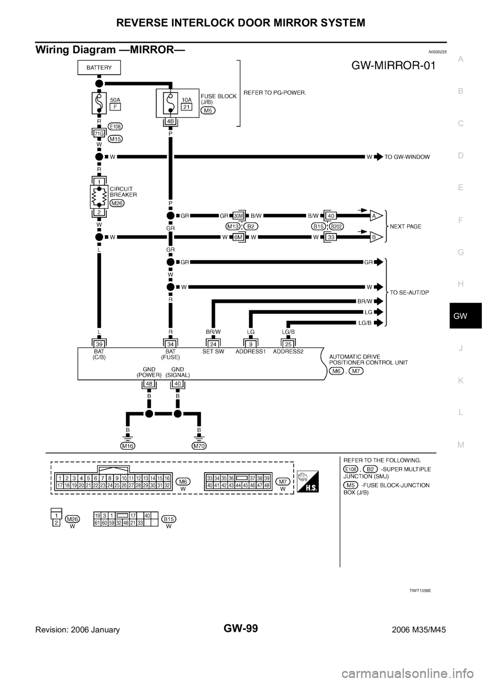
Wiring Diagram —MIRROR—NIS00235
TIWT1358E
Page 3643 of 5621
IDX-2
ALPHABETICAL INDEX
A
A/C air flow ...................................................... ATC-37
A/C component layout ..................................... ATC-25
A/C compressor mounting ........... ATC-155, ATC-158,
ATC-159
, ATC-160, ATC-162, ATC-164, ATC-165,
ATC-167
, ATC-168, ATC-169
A/C compressor precaution ............................. ATC-12
A/C compressor special service tool ................ ATC-16
A/C control operation (auto A/C) ...................... ATC-33
A/C diagnostic work flow (auto A/C) .............. ATC-111
A/C evaporator ............................................... ATC-168
A/C HFC134a (R134a) system precaution ........ ATC-6
A/C HFC134a (R134a) system service procedure .......
ATC-151
A/C HFC134a (R134a) system service tools ... ATC-17
A/C HFC134a system service equipment precaution ...
ATC-13
A/C lubricant (R134a) ...................................... ATC-26
A/C lubrication oil ........................................... ATC-174
A/C operational check ...................................... ATC-64
A/C self-diagnoses (auto A/C) ........ ATC-55, ATC-111
A/C service data specification ........................ ATC-174
A/C system description (auto A/C) ................... ATC-29
A/C trouble diagnoses (auto A/C) .................... ATC-40
A/C, A - Wiring diagram ................................... ATC-46
A/T fluid checking ...................... AT-13, AT-53, MA-29
A/T fluid cooler cleaning .................................... AT-14
A/T fluid replacement ............................. AT-12, MA-31
A/T fluid temperature sensor ........................... AT-135
A/T IND - Wiring diagram .................................... DI-57
A/T self-diagnoses ............................... AT-92, AT-103
A/T shift lock system ........................................ AT-229
A/T shift lock system - Wiring diagram ............ AT-230
A/T trouble diagnoses ........................................ AT-44
Accelerator control system ............................... ACC-3
Accelerator pedal position (APP) sensor ........ EC-626,
EC-633
, EC-647, EC-1358, EC-1365, EC-1379
Accelerator pedal released position learning .... EC-95,
EC-806
AF1B1-Wiring diagram ...... EC-249, EC-258, EC-267,
EC-277
, EC-657, EC-972, EC-981, EC-990, EC-1000,
EC-1389
AF1B2-Wiring diagram ...... EC-251, EC-260, EC-269,
EC-279
, EC-659, EC-974, EC-983, EC-992, EC-1002,
EC-1391
AF1HB1-Wiring diagram .................... EC-183, EC-905
AF1HB2-Wiring diagram .................... EC-185, EC-907
Air bag .............................................................. SRS-3
Air bag precautions ........................................... SRS-3
Air cleaner and air duct(VK45DE) ................... EM-177
Air cleaner and air duct(VQ35DE) .................... EM-17
Air cleaner filter replacement ............................ MA-25
Air cleaner filter replacement(VQ35DE) ........... MA-18
Air cleaner filter(VQ35DE) ................................ EM-18
Air conditioner cut control .................... EC-35, EC-745
Air flow meter - See Mass air flow sensor ...... EC-205,
EC-214
, EC-927, EC-936
Air fuel ratio sensor 1 ......... EC-246, EC-256, EC-265, EC-274
, EC-655, EC-969, EC-979, EC-988, EC-997,
EC-1387
Air fuel ratio sensor 1 heater ............. EC-182, EC-904
Air mix. door motor ......................... ATC-83, ATC-141
Alternator ........................................................... SC-23
Ambient sensor ............................. ATC-113, ATC-126
Angular tightening application ............................. EM-6
Angular tightening application(VK45DE) ........ EM-164
APPS1 - Wiring diagram ................. EC-628, EC-1360
APPS2 - Wiring diagram ................. EC-635, EC-1367
APPS3 - Wiring diagram ................. EC-649, EC-1381
ASC/BS - Wiring diagram ............... EC-587, EC-1313
ASC/SW - Wiring diagram .............. EC-570, EC-1296
ASCBOF - Wiring diagram .............. EC-708, EC-1450
ASCD .................................................. EC-36, EC-746
ASCD (automatic speed control device) ........... ACS-3
ASCIND - Wiring diagram ............... EC-715, EC-1457
AT indicator lamp ................................................ DI-56
Auto air conditioner - Wiring diagram ............. ATC-46
Auto amp ...................................................... ATC-125
Auto anti-dazzling inside mirror .......... GW-71, GW-72
Automatic amplifier ........... ATC-53, ATC-66, ATC-125
Automatic transmission fluid replacement ........ MA-32
AWD - Wiring diagram ....................................... TF-17
Axle ................................................................... MA-37
B
Back-up lamp ................................................... LT-246
Basic inspection .................................. EC-77, EC-788
Battery ................................................................. SC-4
Battery current sensor ....... EC-537, EC-543, EC-549,
EC-555
, EC-1263, EC-1269, EC-1275, EC-1281
Battery/Starting/Charging System Tester .......... SC-28
Battery/Starting/Charging System Tester(Battery) SC-7
Battery/Starting/Charging System Tester(Starting
system) .............................................................. SC-13
BCM (Body control module) .............................. BCS-3
Block heater(VK45DE) .................................... EM-249
Block heater(VQ35DE) ................................... EM-123
Blower motor ................................... ATC-89, ATC-132
Blower unit .................................................... ATC-130
Brake fluid level ................................................ MA-35
Brake hydraulic line ........................................... BR-12
Brake inspection ............................................... MA-36
Brake lines and cables inspection .................... MA-35
Brake pedal .......................................................... BR-6
Brake switch ................................... EC-598, EC-1329
BRK/SW - Wiring diagram .............. EC-600, EC-1331
Bulb specifications ........................................... LT-315
Bumper, front ...................................................... EI-11
Bumper, rear ....................................................... EI-14
C
Camshaft inspection(VK45DE) ....................... EM-216
Camshaft inspection(VQ35DE) ......................... EM-86
Camshaft position sensor (PHASE) EC-383, EC-1106
Camshaft(VK45DE) ........................................ EM-215