2006 INFINITI M35 load capacity
[x] Cancel search: load capacityPage 2656 of 5621
![INFINITI M35 2006 Factory Service Manual DTC P0420, P0430 THREE WAY CATALYST FUNCTION
EC-1113
[VK45DE]
C
D
E
F
G
H
I
J
K
L
MA
EC
Revision: 2006 January2006 M35/M45
DTC P0420, P0430 THREE WAY CATALYST FUNCTIONPFP:20905
On Board Diagnosis Logi INFINITI M35 2006 Factory Service Manual DTC P0420, P0430 THREE WAY CATALYST FUNCTION
EC-1113
[VK45DE]
C
D
E
F
G
H
I
J
K
L
MA
EC
Revision: 2006 January2006 M35/M45
DTC P0420, P0430 THREE WAY CATALYST FUNCTIONPFP:20905
On Board Diagnosis Logi](/manual-img/42/57023/w960_57023-2655.png)
DTC P0420, P0430 THREE WAY CATALYST FUNCTION
EC-1113
[VK45DE]
C
D
E
F
G
H
I
J
K
L
MA
EC
Revision: 2006 January2006 M35/M45
DTC P0420, P0430 THREE WAY CATALYST FUNCTIONPFP:20905
On Board Diagnosis LogicNBS005GS
The ECM monitors the switching frequency ratio of air fuel ratio (A/F)
sensor 1 and heated oxygen sensor 2.
A three way catalyst (manifold) with high oxygen storage capacity
will indicate a low switching frequency of heated oxygen sensor 2.
As oxygen storage capacity decreases, the heated oxygen sensor 2
switching frequency will increase.
When the frequency ratio of A/F sensor 1 and heated oxygen sensor
2 approaches a specified limit value, the three way catalyst (mani-
fold) malfunction is diagnosed.
DTC Confirmation ProcedureNBS005GT
NOTE:
If DTC Confirmation Procedure has been previously conducted, always turn ignition switch OFF and wait at
least 10 seconds before conducting the next test.
WITH CONSULT-II
TESTING CONDITION:
Do not hold engine speed for more than the specified minutes below.
1. Turn ignition switch ON and select “DATA MONITOR” mode with
CONSULT-II.
2. Start engine and warm it up to the normal operating tempera-
ture.
3. Turn ignition switch OFF and wait at least 10 seconds.
4. Start engine and keep the engine speed between 3,500 and
4,000 rpm for at least 1 minute under no load.
5. Let engine idle for 1 minute.
6. Make sure that “COOLAN TEMP/S” indicates more than 70
C
(158
F).
If not, warm up engine and go to next step when “COOLAN
TEMP/S” indication reaches to 70
C (158F).
7. Open engine hood.
PBIB2055E
DTC No. Trouble diagnosis name DTC detecting condition Possible cause
P0420
0420
(Bank 1)
Catalyst system effi-
ciency below threshold
Three way catalyst (manifold) does not oper-
ate properly.
Three way catalyst (manifold) does not have
enough oxygen storage capacity.
Three way catalyst (manifold)
Exhaust tube
Intake air leaks
Fuel injector
Fuel injector leaks
Spark plug
Improper ignition timing P0430
0430
(Bank 2)
SEF189Y
Page 3188 of 5621
![INFINITI M35 2006 Factory Service Manual CYLINDER BLOCK
EM-125
[VQ35DE]
C
D
E
F
G
H
I
J
K
L
MA
EM
Revision: 2006 January2006 M35/M45
CAUTION:
Do not disassemble drive plate.
Never place drive plate with signal plate facing down.
When handlin INFINITI M35 2006 Factory Service Manual CYLINDER BLOCK
EM-125
[VQ35DE]
C
D
E
F
G
H
I
J
K
L
MA
EM
Revision: 2006 January2006 M35/M45
CAUTION:
Do not disassemble drive plate.
Never place drive plate with signal plate facing down.
When handlin](/manual-img/42/57023/w960_57023-3187.png)
CYLINDER BLOCK
EM-125
[VQ35DE]
C
D
E
F
G
H
I
J
K
L
MA
EM
Revision: 2006 January2006 M35/M45
CAUTION:
Do not disassemble drive plate.
Never place drive plate with signal plate facing down.
When handling signal plate, take care not to damage or
scratch it.
Handle signal plate in a manner that prevents it from
becoming magnetized.
3. Lift the engine with hoist to install it onto the widely use engine stand.
CAUTION:
Use an engine stand that has a load capacity [220 kg (441 lb) or more] large enough for supporting
the engine weight.
If the load capacity of the stand is not adequate, remove the following parts beforehand to reduce the
potential risk of overturning the stand.
–Remove intake manifold collector. Refer to EM-19, "INTAKE MANIFOLD COLLECTOR" .
–Remove intake manifold. Refer to EM-24, "INTAKE MANIFOLD" .
–Remove fuel injector and fuel tube assembly. Refer to EM-45, "FUEL INJECTOR AND FUEL TUBE" .
–Remove ignition coil. Refer to EM-42, "IGNITION COIL" .
–Remove rocker cover. Refer to EM-51, "ROCKER COVER" .
–Remove exhaust manifold. Refer to EM-26, "EXHAUST MANIFOLD" .
–Other removable brackets.
NOTE:
The figure shows an example of widely use engine stand that
can hold mating surface of transmission with drive plate
removed.
CAUTION:
Before removing the hanging chains, make sure the
engine stand is stable and there is no risk of overturning.
4. Drain engine oil. Refer to LU-9, "
Changing Engine Oil" .
SEM760G
PBIC0085E
Page 3313 of 5621
![INFINITI M35 2006 Factory Service Manual EM-250
[VK45DE]
CYLINDER BLOCK
Revision: 2006 January2006 M35/M45
Disassembly and AssemblyNBS004PN
DISASSEMBLY
NOTE:
Explained here is how to disassemble with engine stand supporting transmission su INFINITI M35 2006 Factory Service Manual EM-250
[VK45DE]
CYLINDER BLOCK
Revision: 2006 January2006 M35/M45
Disassembly and AssemblyNBS004PN
DISASSEMBLY
NOTE:
Explained here is how to disassemble with engine stand supporting transmission su](/manual-img/42/57023/w960_57023-3312.png)
EM-250
[VK45DE]
CYLINDER BLOCK
Revision: 2006 January2006 M35/M45
Disassembly and AssemblyNBS004PN
DISASSEMBLY
NOTE:
Explained here is how to disassemble with engine stand supporting transmission surface. When using differ-
ent type of engine stand, note with difference in steps and etc.
1. Remove engine assembly from vehicle, and separate front suspension member, transmission from
engine. Refer to EM-244, "
ENGINE ASSEMBLY" .
2. Remove the parts that may restrict installation of engine to widely use engine stand.
NOTE:
The procedure is described assuming that you use widely use engine holding the surface, to which trans-
mission is installed.
a. Remove drive plate.
Holding ring gear with ring gear stopper (SST).
Loosen mounting bolts diagonally order.
CAUTION:
Do not disassemble drive plate.
Do not place drive plate with signal plate facing down.
When handling signal plate, take care not to damage or
scratch it.
Handle signal plate in a manner that prevents it from
becoming magnetized.
b. Remove rear plate.
3. Lift engine with hoist to install it onto widely use engine stand.
CAUTION:
Use engine stand that has a load capacity [approximately 240kg (529 lb) or more] large enough for
supporting the engine weight.
If the load capacity of stand is not adequate, remove the following parts beforehand to reduce the
potential risk of overturning stand.
–Intake manifolds (upper and lower); Refer to EM-179, "INTAKE MANIFOLD" .
–Exhaust manifold and three way catalyst; Refer to EM-183, "EXHAUST MANIFOLD AND THREE WAY
CATALYST" .
13. Piston pin 14. Connecting rod bearing 15. Connecting rod bearing cap
16. Block heater protector 17. Connector cap 18. Cylinder block heater
19. Gasket 20. Main bearing cap 21. Thrust bearing
22. Main bearing 23. Rear plate 24. Crankshaft
25. Pilot convertor 26. Drive plate 27. Thrust bearing
28. Side bolt 29. Reinforcement plate 30. Crankshaft position sensor (POS)
31. O-ring 32. Rear oil seal 33. Rear oil seal retainer
PBIC1656E
PBIC2367E
Page 3412 of 5621

SERVICE DATA AND SPECIFICATIONS (SDS)
FFD-35
C
E
F
G
H
I
J
K
L
MA
B
FFD
Revision: 2006 January2006 M35/M45
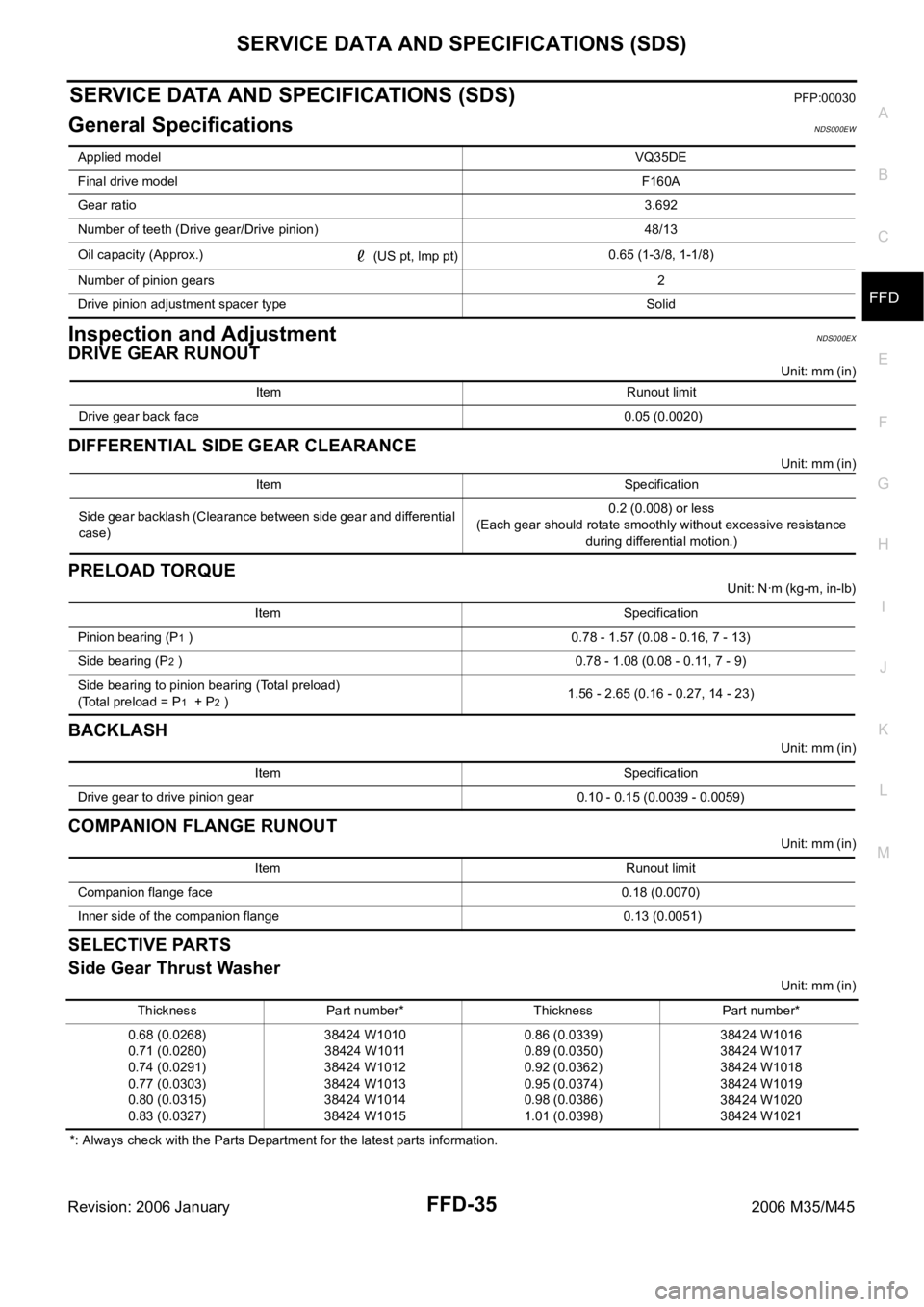
SERVICE DATA AND SPECIFICATIONS (SDS)PFP:00030
General SpecificationsNDS000EW
Inspection and AdjustmentNDS000EX
DRIVE GEAR RUNOUT
Unit: mm (in)
DIFFERENTIAL SIDE GEAR CLEARANCE
Unit: mm (in)
PRELOAD TORQUE
Unit: Nꞏm (kg-m, in-lb)
BACKLASH
Unit: mm (in)
COMPANION FLANGE RUNOUT
Unit: mm (in)
SELECTIVE PARTS
Side Gear Thrust Washer
Unit: mm (in)
*: Always check with the Parts Department for the latest parts information. Applied modelVQ35DE
Final drive modelF160A
Gear ratio3.692
Number of teeth (Drive gear/Drive pinion) 48/13
Oil capacity (Approx.)
(US pt, lmp pt)0.65 (1-3/8, 1-1/8)
Number of pinion gears2
Drive pinion adjustment spacer type Solid
Item Runout limit
Drive gear back face 0.05 (0.0020)
Item Specification
Side gear backlash (Clearance between side gear and differential
case)0.2 (0.008) or less
(Each gear should rotate smoothly without excessive resistance
during differential motion.)
Item Specification
Pinion bearing (P
1 ) 0.78 - 1.57 (0.08 - 0.16, 7 - 13)
Side bearing (P
2 ) 0.78 - 1.08 (0.08 - 0.11, 7 - 9)
Side bearing to pinion bearing (Total preload)
(Total preload = P
1 + P2 )1.56 - 2.65 (0.16 - 0.27, 14 - 23)
Item Specification
Drive gear to drive pinion gear 0.10 - 0.15 (0.0039 - 0.0059)
Item Runout limit
Companion flange face 0.18 (0.0070)
Inner side of the companion flange 0.13 (0.0051)
Thickness Part number* Thickness Part number*
0.68 (0.0268)
0.71 (0.0280)
0.74 (0.0291)
0.77 (0.0303)
0.80 (0.0315)
0.83 (0.0327)38424 W1010
38424 W1011
38424 W1012
38424 W1013
38424 W1014
38424 W10150.86 (0.0339)
0.89 (0.0350)
0.92 (0.0362)
0.95 (0.0374)
0.98 (0.0386)
1.01 (0.0398)38424 W1016
38424 W1017
38424 W1018
38424 W1019
38424 W1020
38424 W1021
Page 5080 of 5621

SERVICE DATA AND SPECIFICATIONS (SDS)
RFD-37
C
E
F
G
H
I
J
K
L
MA
B
RFD
Revision: 2006 January2006 M35/M45
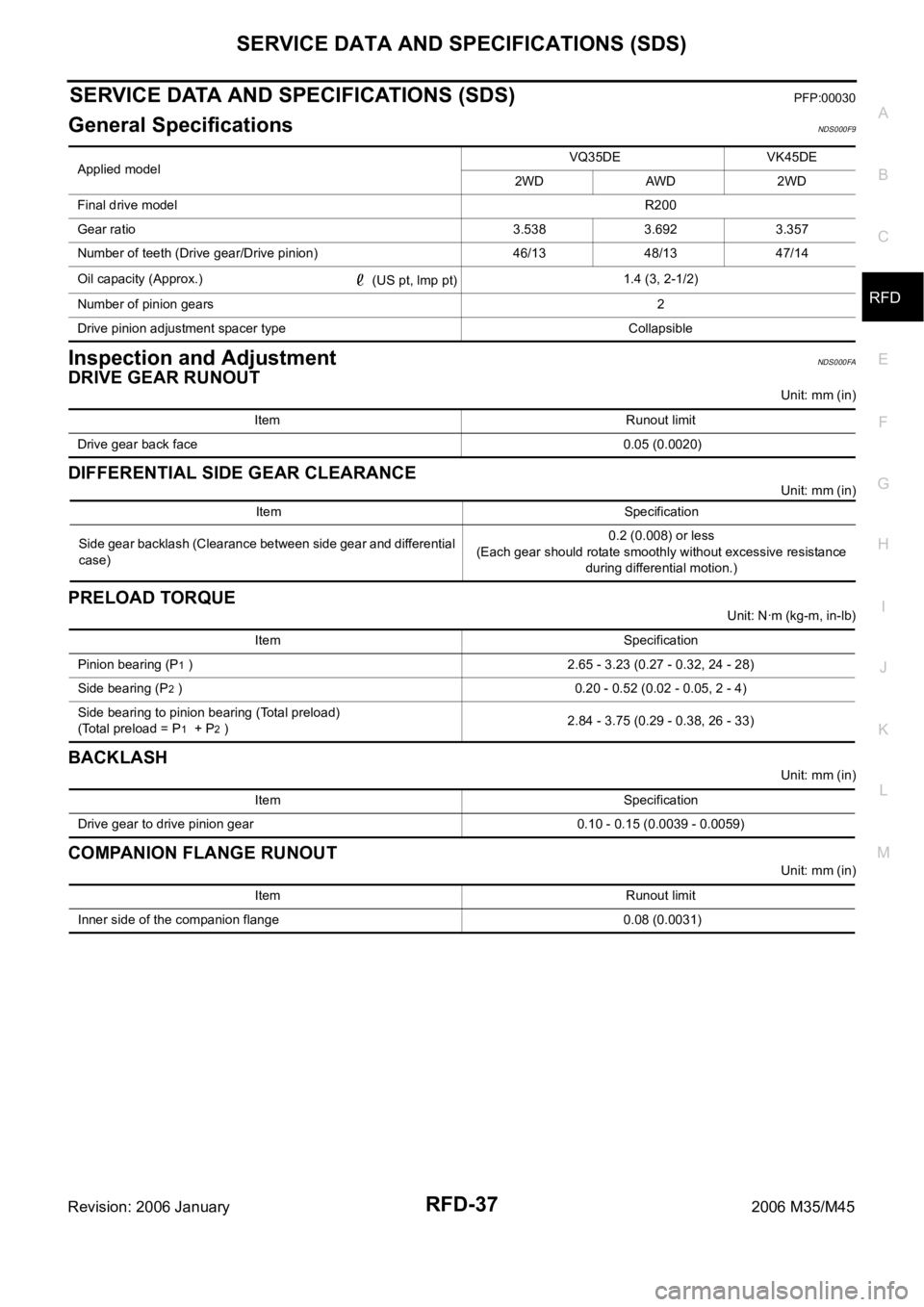
SERVICE DATA AND SPECIFICATIONS (SDS)PFP:00030
General SpecificationsNDS000F9
Inspection and AdjustmentNDS000FA
DRIVE GEAR RUNOUT
Unit: mm (in)
DIFFERENTIAL SIDE GEAR CLEARANCE
Unit: mm (in)
PRELOAD TORQUE
Unit: Nꞏm (kg-m, in-lb)
BACKLASH
Unit: mm (in)
COMPANION FLANGE RUNOUT
Unit: mm (in) Applied modelVQ35DE VK45DE
2WD AWD 2WD
Final drive modelR200
Gear ratio 3.538 3.692 3.357
Number of teeth (Drive gear/Drive pinion) 46/13 48/13 47/14
Oil capacity (Approx.)
(US pt, lmp pt)1.4 (3, 2-1/2)
Number of pinion gears2
Drive pinion adjustment spacer type Collapsible
Item Runout limit
Drive gear back face 0.05 (0.0020)
Item Specification
Side gear backlash (Clearance between side gear and differential
case)0.2 (0.008) or less
(Each gear should rotate smoothly without excessive resistance
during differential motion.)
Item Specification
Pinion bearing (P
1 ) 2.65 - 3.23 (0.27 - 0.32, 24 - 28)
Side bearing (P
2 ) 0.20 - 0.52 (0.02 - 0.05, 2 - 4)
Side bearing to pinion bearing (Total preload)
(Total preload = P
1 + P2 )2.84 - 3.75 (0.29 - 0.38, 26 - 33)
Item Specification
Drive gear to drive pinion gear 0.10 - 0.15 (0.0039 - 0.0059)
Item Runout limit
Inner side of the companion flange 0.08 (0.0031)
Page 5180 of 5621

SERVICE DATA AND SPECIFICATIONS (SDS)
SC-43
C
D
E
F
G
H
I
J
L
MA
B
SC
Revision: 2006 January2006 M35/M45
SERVICE DATA AND SPECIFICATIONS (SDS)PFP:00030
BatteryNKS003NT
StarterNKS003NU
AlternatorNKS003NV
*: Adjustment range of power generation voltage variable control is 11.4 - 15.6 V. Ty p e110D26L
20 hour rate capacity [V - Ah] 12 - 75
Cold cranking current (For reference value) [A] 720
Applied modelVK45DE VQ35DE VQ35DE
2WD AWD
Ty p eM2T85771 S114-880 S114-881
MITSUBISHI
makeHITACHI make
Reduction gear type
System voltage [V] 12
No-loadTerminal voltage [V] 11
Current [A] Less than 145 Less than 90
Revolution [rpm] More than 3,300 More than 2,880
Minimum diameter of commutator [mm (in)] 31.4 (1.236) 28.0 (1.102)
Minimum length of brush [mm (in)] 11.0 (0.433) 10.5 (0.413)
Brush spring tension [N (kg, lb)]26.7 - 36.1
(2.72 - 3.68,
6.80 - 8.12)16.2 (1.65, 3.6)
Clearance between bearing metal and armature shaft [mm (in)] Less than 0.2 (0.008)
Clearance between pinion front edge and pinion stopper [mm (in)]0.5 - 2.0
(0.020 - 0.079)0.3 - 2.5 (0.012 - 0.098)
Applied model VK45DE VQ35DE
Ty p eA3TJ0591 A3TJ0691
MITSUBISHI make
Nominal rating [V - A] 12 -150
Ground polarityNegative
Minimum revolution under no-load (When 13.5 V is
applied)[rpm] Less than 1,300
Hot output current (When 13.5 V is applied) [A/rpm]More than 35/1,300
More than 105/2,500
More than 136/5,000
Regulated output voltage [V] 14.1 - 14.7 *
Minimum length of brush [mm (in)] More than 5.00 (0.197)
Brush spring pressure [N (g, oz)] 4.1 - 5.3 (418 - 540, 14.8 - 19.1)
Slip ring minimum outer diameter [mm (in)] More than 22.1 (0.870)
Rotor (Field coil) resistance [
] 1.6 - 2.0