2006 INFINITI M35 fuel pressure
[x] Cancel search: fuel pressurePage 1466 of 5621

UNIFIED METER AND A/C AMP
DI-33
C
D
E
F
G
H
I
J
L
MA
B
DI
Revision: 2006 January2006 M35/M45
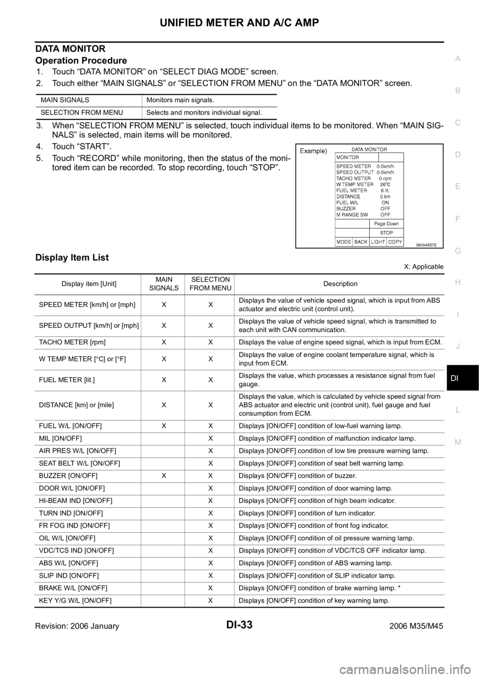
DATA MONITOR
Operation Procedure
1. Touch “DATA MONITOR” on “SELECT DIAG MODE” screen.
2. Touch either “MAIN SIGNALS” or “SELECTION FROM MENU” on the “DATA MONITOR” screen.
3. When “SELECTION FROM MENU” is selected, touch individual items to be monitored. When “MAIN SIG-
NALS” is selected, main items will be monitored.
4. Touch “START”.
5. Touch “RECORD” while monitoring, then the status of the moni-
tored item can be recorded. To stop recording, touch “STOP”.
Display Item List
X: Applicable MAIN SIGNALS Monitors main signals.
SELECTION FROM MENU Selects and monitors individual signal.
SKIA4957E
Display item [Unit]MAIN
SIGNALSSELECTION
FROM MENUDescription
SPEED METER [km/h] or [mph] X XDisplays the value of vehicle speed signal, which is input from ABS
actuator and electric unit (control unit).
SPEED OUTPUT [km/h] or [mph] X XDisplays the value of vehicle speed signal, which is transmitted to
each unit with CAN communication.
TACHO METER [rpm] X X Displays the value of engine speed signal, which is input from ECM.
W TEMP METER [
C] or [F] X XDisplays the value of engine coolant temperature signal, which is
input from ECM.
FUEL METER [lit.] X XDisplays the value, which processes a resistance signal from fuel
gauge.
DISTANCE [km] or [mile] X XDisplays the value, which is calculated by vehicle speed signal from
ABS actuator and electric unit (control unit), fuel gauge and fuel
consumption from ECM.
FUEL W/L [ON/OFF] X X Displays [ON/OFF] condition of low-fuel warning lamp.
MIL [ON/OFF] X Displays [ON/OFF] condition of malfunction indicator lamp.
AIR PRES W/L [ON/OFF] X Displays [ON/OFF] condition of low tire pressure warning lamp.
SEAT BELT W/L [ON/OFF] X Displays [ON/OFF] condition of seat belt warning lamp.
BUZZER [ON/OFF] X X Displays [ON/OFF] condition of buzzer.
DOOR W/L [ON/OFF] X Displays [ON/OFF] condition of door warning lamp.
HI-BEAM IND [ON/OFF] X Displays [ON/OFF] condition of high beam indicator.
TURN IND [ON/OFF] X Displays [ON/OFF] condition of turn indicator.
FR FOG IND [ON/OFF] X Displays [ON/OFF] condition of front fog indicator.
OIL W/L [ON/OFF] X Displays [ON/OFF] condition of oil pressure warning lamp.
VDC/TCS IND [ON/OFF] X Displays [ON/OFF] condition of VDC/TCS OFF indicator lamp.
ABS W/L [ON/OFF] X Displays [ON/OFF] condition of ABS warning lamp.
SLIP IND [ON/OFF] X Displays [ON/OFF] condition of SLIP indicator lamp.
BRAKE W/L [ON/OFF] X Displays [ON/OFF] condition of brake warning lamp. *
KEY Y/G W/L [ON/OFF] X Displays [ON/OFF] condition of key warning lamp.
Page 1514 of 5621

LANE DEPARTURE WARNING SYSTEM
DI-81
C
D
E
F
G
H
I
J
L
MA
B
DI
Revision: 2006 January2006 M35/M45
Camera Aiming AdjustmentNKS003VI
OUTLINE
Adjust the camera aiming every time the LDW camera unit is removed or installed.
CAUTION:
Place the vehicle on the level ground when the camera aiming adjustment is operated.
Follow the CONSULT-II when adjusting the camera aiming. (Camera aiming adjustment cannot be
operated without CONSULT-II.)
PREPARATION
Keep all tires inflated to correct pressures. Adjust the tire pressure to the specified pressure value.
There is no-load in vehicle. Check if coolant, engine oil are filled up to correct level and fuel tank is full.
Shift the gear into “P” position and release the parking brake.
Clean the windshield.
NOTE:
Do not place anything reflective on the upper surface of instrument panel.
TARGET SETTING
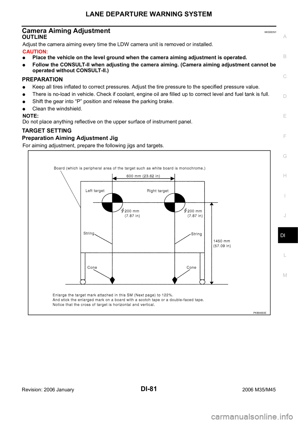
Preparation Aiming Adjustment Jig
For aiming adjustment, prepare the following jigs and targets.
PKIB4693E
Page 1544 of 5621

EC-1
ENGINE CONTROL SYSTEM
B ENGINE
CONTENTS
C
D
E
F
G
H
I
J
K
L
M
SECTION EC
A
EC
Revision: 2006 January2006 M35/M45
ENGINE CONTROL SYSTEM
VQ35DE
INDEX FOR DTC ...................................................... 16
DTC No. Index ....................................................... 16
Alphabetical Index .................................................. 20
PRECAUTIONS ........................................................ 24
Precautions for Supplemental Restraint System
(SRS) “AIR BAG” and “SEAT BELT PRE-TEN-
SIONER” ................................................................ 24
Precautions for Procedures without Cowl Top Cover ... 24
On Board Diagnostic (OBD) System of Engine and
A/T .......................................................................... 24
Precaution .............................................................. 25
PREPARATION ......................................................... 28
Special Service Tools ............................................. 28
Commercial Service Tools ...................................... 29
ENGINE CONTROL SYSTEM .................................. 30
System Diagram ..................................................... 30
Multiport Fuel Injection (MFI) System .................... 31
Electronic Ignition (EI) System ............................... 33
Fuel Cut Control (At No Load and High Engine
Speed) .................................................................... 34
AIR CONDITIONING CUT CONTROL ..................... 35
Input/Output Signal Chart ....................................... 35
System Description ................................................ 35
AUTOMATIC SPEED CONTROL DEVICE (ASCD) ... 36
System Description ................................................ 36
Component Description .......................................... 37
CAN COMMUNICATION .......................................... 38
System Description ................................................ 38
EVAPORATIVE EMISSION SYSTEM ....................... 39
Description ............................................................. 39
Component Inspection ........................................... 42
Removal and Installation ........................................ 43
How to Detect Fuel Vapor Leakage ....................... 43
ON BOARD REFUELING VAPOR RECOVERY
(ORVR) ...................................................................... 46
System Description ................................................ 46
Diagnostic Procedure ............................................. 47
Component Inspection ........................................... 49POSITIVE CRANKCASE VENTILATION ................. 51
Description .............................................................. 51
Component Inspection ............................................ 51
IVIS (INFINITI VEHICLE IMMOBILIZER SYSTEM-
NATS) ........................................................................ 53
Description .............................................................. 53
ON BOARD DIAGNOSTIC (OBD) SYSTEM ............ 54
Introduction ..................................................
........... 54
Two Trip Detection Logic ........................................ 54
Emission-Related Diagnostic Information ............... 55
Malfunction Indicator Lamp (MIL) ........................... 69
OBD System Operation Chart ................................ 72
BASIC SERVICE PROCEDURE ............................... 77
Basic Inspection ..................................................... 77
Idle Speed and Ignition Timing Check .................... 82
Idle Mixture Ratio Adjustment ................................. 84
VIN Registration ..................................................... 95
Accelerator Pedal Released Position Learning ...... 95
Throttle Valve Closed Position Learning ................. 95
Idle Air Volume Learning ........................................ 96
Fuel Pressure Check .............................................. 98
TROUBLE DIAGNOSIS ..........................................100
Trouble Diagnosis Introduction .............................100
DTC Inspection Priority Chart ...............................106
Fail-Safe Chart .....................................................108
Symptom Matrix Chart ..........................................109
Engine Control Component Parts Location ..........113
Vacuum Hose Drawing .........................................121
Circuit Diagram .....................................................122
ECM Harness Connector Terminal Layout ...........124
ECM Terminals and Reference Value ...................124
CONSULT-II Function (ENGINE) ..........................133
Generic Scan Tool (GST) Function .......................146
CONSULT-II Reference Value in Data Monitor .....149
Major Sensor Reference Graph in Data Monitor
Mode .....................................................................153
TROUBLE DIAGNOSIS - SPECIFICATION VALUE .155
Description ............................................................155
Testing Condition ..................................................155
Page 1550 of 5621

EC-7
C
D
E
F
G
H
I
J
K
L
M
ECA
Revision: 2006 January2006 M35/M45 DTC Confirmation Procedure ...............................607
Wiring Diagram ....................................................609
Diagnostic Procedure ...........................................610
DTC P2101 ELECTRIC THROTTLE CONTROL
FUNCTION ..............................................................613
Description ...........................................................613
On Board Diagnosis Logic ...................................613
DTC Confirmation Procedure ...............................613
Wiring Diagram ....................................................614
Diagnostic Procedure ...........................................615
Component Inspection .........................................618
Removal and Installation ......................................618
DTC P2118 THROTTLE CONTROL MOTOR ........619
Component Description ........................................619
On Board Diagnosis Logic ...................................619
DTC Confirmation Procedure ...............................619
Wiring Diagram ....................................................620
Diagnostic Procedure ...........................................621
Component Inspection .........................................622
Removal and Installation ......................................623
DTC P2119 ELECTRIC THROTTLE CONTROL
ACTUATOR ............................................................624
Component Description ........................................624
On Board Diagnosis Logic ...................................624
DTC Confirmation Procedure ...............................624
Diagnostic Procedure ...........................................625
DTC P2122, P2123 APP SENSOR ........................626
Component Description ........................................626
CONSULT-II Reference Value in Data Monitor Mode
.626
On Board Diagnosis Logic ...................................626
DTC Confirmation Procedure ...............................627
Wiring Diagram ....................................................628
Diagnostic Procedure ...........................................629
Component Inspection .........................................631
Removal and Installation ......................................632
DTC P2127, P2128 APP SENSOR ........................633
Component Description ........................................633
CONSULT-II Reference Value in Data Monitor Mode
.633
On Board Diagnosis Logic ...................................633
DTC Confirmation Procedure ...............................634
Wiring Diagram ....................................................635
Diagnostic Procedure ...........................................636
Component Inspection .........................................639
Removal and Installation ......................................639
DTC P2135 TP SENSOR ........................................640
Component Description ........................................640
CONSULT-II Reference Value in Data Monitor Mode
.640
On Board Diagnosis Logic ...................................640
DTC Confirmation Procedure ...............................641
Wiring Diagram ....................................................642
Diagnostic Procedure ...........................................643
Component Inspection .........................................646
Removal and Installation ......................................646
DTC P2138 APP SENSOR .....................................647
Component Description ........................................647
CONSULT-II Reference Value in Data Monitor Mode .647
On Board Diagnosis Logic ....................................647
DTC Confirmation Procedure ...............................648
Wiring Diagram .....................................................649
Diagnostic Procedure ...........................................650
Component Inspection ..........................................654
Removal and Installation ......................................654
DTC P2A00, P2A03 A/F SENSOR 1 ......................655
Component Description ........................................655
CONSULT-II Reference Value in Data Monitor Mode
.655
On Board Diagnosis Logic ....................................655
DTC Confirmation Procedure ...............................655
Wiring Diagram .....................................................657
Diagnostic Procedure ...........................................660
Removal and Installation ......................................665
IGNITION SIGNAL ..................................................666
Component Description ........................................666
Wiring Diagram .....................................................667
Diagnostic Procedure ...........................................672
Component Inspection ..........................................677
Removal and Installation ......................................678
FUEL INJECTOR ....................................................679
Component Description ........................................679
CONSULT-II Reference Value in Data Monitor Mode
.679
Wiring Diagram .....................................................680
Diagnostic Procedure ...........................................681
Component Inspection ..........................................684
Removal and Installation ......................................684
FUEL PUMP ............................................................685
Description ............................................................685
CONSULT-II Reference Value in Data Monitor Mode
.685
Wiring Diagram .....................................................686
Diagnostic Procedure ...........................................687
Component Inspection ..........................................691
Removal and Installation ......................................691
REFRIGERANT PRESSURE SENSOR ..................692
Component Description ........................................692
Wiring Diagram .....................................................693
Diagnostic Procedure ...........................................694
Removal and Installation ......................................696
ELECTRICAL LOAD SIGNAL ................................697
Description ............................................................697
CONSULT-II Reference Value in Data Monitor Mode
.697
Diagnostic Procedure ...........................................697
ICC BRAKE SWITCH .............................................699
Component Description ........................................699
CONSULT-II Reference Value in Data Monitor Mode
.699
Wiring Diagram .....................................................700
Diagnostic Procedure ...........................................701
Component Inspection ..........................................705
ASCD BRAKE SWITCH .........................................707
Component Description ........................................707
CONSULT-II Reference Value in Data Monitor Mode
.707
Page 1551 of 5621

EC-8Revision: 2006 January2006 M35/M45 Wiring Diagram .....................................................708
Diagnostic Procedure ...........................................709
Component Inspection ..........................................713
ASCD INDICATOR .................................................
.714
Component Description ........................................714
CONSULT-II Reference Value in Data Monitor Mode
.714
Wiring Diagram .....................................................715
Diagnostic Procedure ...........................................716
SNOW MODE SWITCH ...........................................717
Description ............................................................717
CONSULT-II Reference Value in the Data Monitor
Mode .....................................................................717
Wiring Diagram .....................................................718
Diagnostic Procedure ...........................................719
Component Inspection ..........................................721
MIL AND DATA LINK CONNECTOR ......................722
Wiring Diagram .....................................................722
SERVICE DATA AND SPECIFICATIONS (SDS) ....724
Fuel Pressure .......................................................724
Idle Speed and Ignition Timing .............................724
Calculated Load Value ..........................................724
Mass Air Flow Sensor ...........................................724
Intake Air Temperature Sensor .............................724
Engine Coolant Temperature Sensor ...................724
Fuel Tank Temperature Sensor ............................724
Crankshaft Position Sensor (POS) .......................724
Camshaft Position Sensor (PHASE) ....................724
A/F Sensor 1 Heater ............................................ .724
Heated Oxygen Sensor 2 Heater .........................725
Throttle Control Motor ...........................................725
Fuel Injector ..........................................................725
Fuel Pump ............................................................725
VK45DE
INDEX FOR DTC .....................................................726
DTC No. Index ......................................................726
Alphabetical Index ................................................730
PRECAUTIONS .......................................................734
Precautions for Supplemental Restraint System
(SRS) “AIR BAG” and “SEAT BELT PRE-TEN-
SIONER” ...............................................................734
Precautions for Procedures without Cowl Top Cover .734
On Board Diagnostic (OBD) System of Engine and
A/T ........................................................................734
Precaution ............................................................735
PREPARATION .......................................................738
Special Service Tools ...........................................738
Commercial Service Tools ....................................739
ENGINE CONTROL SYSTEM ................................740
System Diagram ...................................................740
Multiport Fuel Injection (MFI) System ...................741
Electronic Ignition (EI) System .............................743
Fuel Cut Control (At No Load and High Engine
Speed) ..................................................................744
AIR CONDITIONING CUT CONTROL ....................745
Input/Output Signal Chart .....................................745
System Description ...............................................745AUTOMATIC SPEED CONTROL DEVICE (ASCD) .746
System Description ...............................................746
Component Description ........................................747
CAN COMMUNICATION .........................................748
System Description ...............................................748
EVAPORATIVE EMISSION SYSTEM .....................749
Description ............................................................749
Component Inspection ..........................................752
Removal and Installation .......................................753
How to Detect Fuel Vapor Leakage ......................753
ON BOARD REFUELING VAPOR RECOVERY
(ORVR) ....................................................................756
System Description ...............................................756
Diagnostic Procedure ............................................757
Component Inspection ..........................................759
POSITIVE CRANKCASE VENTILATION ................761
Description ............................................................761
Component Inspection ..........................................761
IVIS (INFINITI VEHICLE IMMOBILIZER SYSTEM-
NATS) ......................................................................763
Description ............................................................763
ON BOARD DIAGNOSTIC (OBD) SYSTEM ...........764
Introduction ..........................................................
.764
Two Trip Detection Logic .......................................764
Emission-Related Diagnostic Information .............765
Malfunction Indicator Lamp (MIL) .........................780
OBD System Operation Chart ...............................782
BASIC SERVICE PROCEDURE .............................788
Basic Inspection ....................................................788
Idle Speed and Ignition Timing Check ..................793
Idle Mixture Ratio Adjustment ...............................795
VIN Registration ....................................................806
Accelerator Pedal Released Position Learning .....806
Throttle Valve Closed Position Learning ...............806
Idle Air Volume Learning .......................................807
Fuel Pressure Check ............................................809
TROUBLE DIAGNOSIS ..........................................811
Trouble Diagnosis Introduction .............................811
DTC Inspection Priority Chart ...............................817
Fail-Safe Chart ......................................................819
Symptom Matrix Chart ..........................................820
Engine Control Component Parts Location ...........824
Vacuum Hose Drawing .........................................833
Circuit Diagram .....................................................834
ECM Harness Connector Terminal Layout ............836
ECM Terminals and Reference Value ...................836
CONSULT-II Function (ENGINE) ..........................846
Generic Scan Tool (GST) Function .......................859
CONSULT-II Reference Value in Data Monitor .....862
Major Sensor Reference Graph in Data Monitor
Mode .....................................................................866
TROUBLE DIAGNOSIS - SPECIFICATION VALUE .868
Description ............................................................868
Testing Condition ..................................................868
Inspection Procedure ...........................................
.868
Diagnostic Procedure ............................................869
TROUBLE DIAGNOSIS FOR INTERMITTENT INCI-
Page 1558 of 5621

EC-15
C
D
E
F
G
H
I
J
K
L
M
ECA
Revision: 2006 January2006 M35/M45 FUEL PUMP ..........................................................1427
Description ..........................................................1427
CONSULT-II Reference Value in Data Monitor Mode
1427
Wiring Diagram ...................................................1428
Diagnostic Procedure ..........................................1429
Component Inspection ........................................1433
Removal and Installation .....................................1433
REFRIGERANT PRESSURE SENSOR ................1434
Component Description .......................................1434
Wiring Diagram ...................................................1435
Diagnostic Procedure ..........................................1436
Removal and Installation .....................................1438
ELECTRICAL LOAD SIGNAL ...............................1439
Description ..........................................................1439
CONSULT-II Reference Value in Data Monitor Mode
1439
Diagnostic Procedure ..........................................1439
ICC BRAKE SWITCH ............................................1441
Component Description .......................................1441
CONSULT-II Reference Value in Data Monitor Mode
1441
Wiring Diagram ...................................................1442
Diagnostic Procedure ..........................................1443
Component Inspection ........................................1447
ASCD BRAKE SWITCH ........................................1449
Component Description .......................................1449
CONSULT-II Reference Value in Data Monitor Mode 1449
Wiring Diagram ....................................................1450
Diagnostic Procedure ..........................................1451
Component Inspection .........................................1455
ASCD INDICATOR ................................................. 1456
Component Description .......................................1456
CONSULT-II Reference Value in Data Monitor Mode
1456
Wiring Diagram ....................................................1457
Diagnostic Procedure ..........................................1458
MIL AND DATA LINK CONNECTOR .....................1459
Wiring Diagram ....................................................1459
SERVICE DATA AND SPECIFICATIONS (SDS) ...1461
Fuel Pressure ......................................................1461
Idle Speed and Ignition Timing ............................1461
Calculated Load Value .........................................1461
Mass Air Flow Sensor ..........................................1461
Intake Air Temperature Sensor ............................1461
Engine Coolant Temperature Sensor ..................1461
Fuel Tank Temperature Sensor ...........................1461
Crankshaft Position Sensor (POS) ......................1461
Camshaft Position Sensor (PHASE) ...................1461
A/F Sensor 1 Heater ............................................ 1461
Heated Oxygen Sensor 2 Heater ........................1462
Throttle Control Motor ..........................................1462
Fuel Injector .........................................................1462
Fuel Pump ...........................................................1462
Page 1570 of 5621
![INFINITI M35 2006 Factory Service Manual PRECAUTIONS
EC-27
[VQ35DE]
C
D
E
F
G
H
I
J
K
L
MA
EC
Revision: 2006 January2006 M35/M45
B1 indicates the bank 1, B2 indicates the bank 2 as shown
in the figure.
Do not operate fuel pump when INFINITI M35 2006 Factory Service Manual PRECAUTIONS
EC-27
[VQ35DE]
C
D
E
F
G
H
I
J
K
L
MA
EC
Revision: 2006 January2006 M35/M45
B1 indicates the bank 1, B2 indicates the bank 2 as shown
in the figure.
Do not operate fuel pump when](/manual-img/42/57023/w960_57023-1569.png)
PRECAUTIONS
EC-27
[VQ35DE]
C
D
E
F
G
H
I
J
K
L
MA
EC
Revision: 2006 January2006 M35/M45
B1 indicates the bank 1, B2 indicates the bank 2 as shown
in the figure.
Do not operate fuel pump when there is no fuel in lines.
–Fuel level sensor unit and fuel pump (1)
–Fuel pressure regulator (2)
–Fuel tank temperature sensor (3)
Tighten fuel hose clamps to the specified torque.
Do not depress accelerator pedal when starting.
Immediately after starting, do not rev up engine unneces-
sarily.
Do not rev up engine just prior to shutdown.
When installing C.B. ham radio or a mobile phone, be sure
to observe the following as it may adversely affect elec-
tronic control systems depending on installation location.
–Keep the antenna as far as possible from the electronic
control units.
–Keep the antenna feeder line more than 20 cm (8 in) away
from the harness of electronic controls.
Do not let them run parallel for a long distance.
–Adjust the antenna and feeder line so that the standing-
wave radio can be kept smaller.
–Be sure to ground the radio to vehicle body.
SEC893C
PBIB2707E
SEF709Y
SEF708Y
Page 1571 of 5621
![INFINITI M35 2006 Factory Service Manual EC-28
[VQ35DE]
PREPARATION
Revision: 2006 January2006 M35/M45
PREPARATIONPFP:00002
Special Service ToolsNBS004S0
The actual shapes of Kent-Moore tools may differ from those of special service tools il INFINITI M35 2006 Factory Service Manual EC-28
[VQ35DE]
PREPARATION
Revision: 2006 January2006 M35/M45
PREPARATIONPFP:00002
Special Service ToolsNBS004S0
The actual shapes of Kent-Moore tools may differ from those of special service tools il](/manual-img/42/57023/w960_57023-1570.png)
EC-28
[VQ35DE]
PREPARATION
Revision: 2006 January2006 M35/M45
PREPARATIONPFP:00002
Special Service ToolsNBS004S0
The actual shapes of Kent-Moore tools may differ from those of special service tools illustrated here.
Tool number
(Kent-Moore No.)
Tool nameDescription
EG17650301
(J-33984-A)
Radiator cap tester
adapterAdapting radiator cap tester to radiator cap and
radiator filler neck
a: 28 (1.10) dia.
b: 31.4 (1.236) dia.
c: 41.3 (1.626) dia.
Unit: mm (in)
KV10117100
(J-36471-A)
Heated oxygen
sensor wrenchLoosening or tightening heated oxygen sensor 2
with 22 mm (0.87 in) hexagon nut
(J-44626)
Air fuel ratio (A/F)
sensor wrenchLoosening tightening air fuel ratio (A/F) sensor 1
KV10114400
(J-38365)
Heated oxygen
sensor wrenchLoosening or tightening air fuel ratio (A/F) sensor
1
a: 22 mm (0.87 in)
(J-44321)
Fuel pressure gauge
kitChecking fuel pressure
KV109E0010
(J-46209)
Break-out boxMeasuring the ECM signals with a circuit tester
KV109E0080
(J-45819)
Y-cable adapterMeasuring the ECM signals with a circuit tester
S-NT564
S-NT379
LEM054
S-NT636
LEC642
S-NT825
S-NT826