Page 1 of 4462
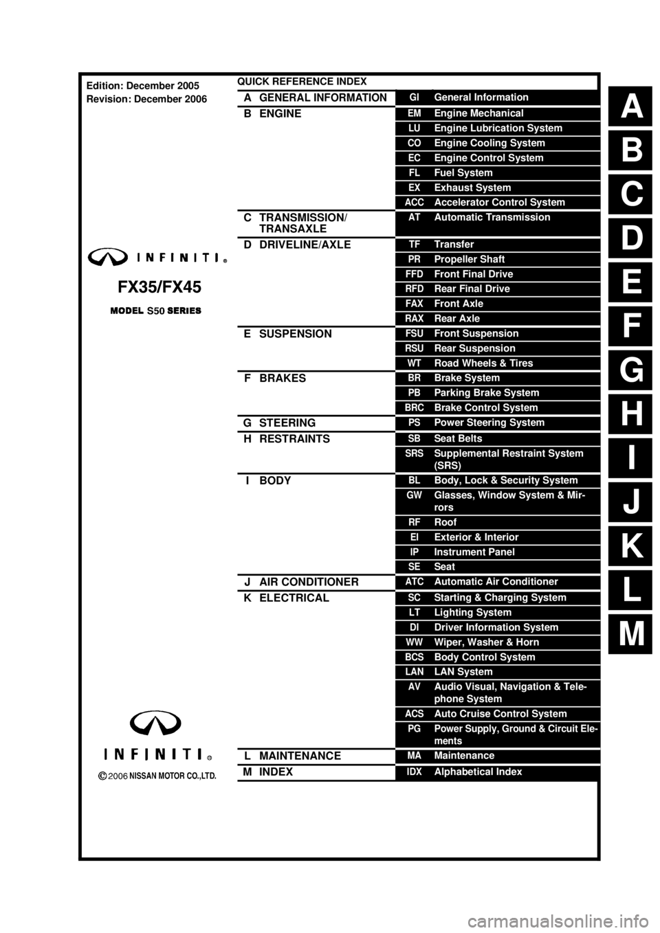
ABCDEFGHIJKMLQUICK REFERENCE INDEX AGENERAL INFORMATIONGIGeneral InformationBENGINEEMEngine MechanicalLUEngine Lubrication SystemCOEngine Cooling SystemECEngine Control SystemFLFuel SystemEXExhaust SystemACCAccelerator Control SystemCTRANSMISSION/
TRANSAXLEATAutomatic TransmissionDDRIVELINE/AXLETFTransferPRPropeller ShaftFFDFront Final DriveRFDRear Final DriveFAXFront AxleRAXRear AxleESUSPENSIONFSUFront SuspensionRSURear SuspensionWTRoad Wheels & TiresFBRAKESBRBrake SystemPBParking Brake SystemBRCBrake Control SystemGSTEERINGPSPower Steering SystemHRESTRAINTSSBSeat BeltsSRSSupplemental Restraint System
(SRS)IBODYBLBody, Lock & Security SystemGWGlasses, Window System & Mir-
rorsRFRoofEIExterior & InteriorIPInstrument PanelSESeatJAIR CONDITIONERATCAutomatic Air ConditionerKELECTRICALSCStarting & Charging SystemLTLighting SystemDIDriver Information SystemWWWiper, Washer & HornBCSBody Control SystemLANLAN SystemAVAudio Visual, Navigation & Tele-
phone SystemACSAuto Cruise Control SystemPGPower Supply, Ground & Circuit Ele-
mentsLMAINTENANCEMAMaintenanceMINDEXIDXAlphabetical IndexEdition: December 2005
Revision: December 2006
Page 3 of 4462

QUICK REFERENCE CHART FX35/FX45
ENGINE TUNE-UP DATA (VK45DE)
FRONT WHEEL ALIGNMENT (Unladen* )
ELS0003X
*: Fuel, engine coolant and lubricant oil full. Spare tire, jack, hand tools and mats are in designated positions.Engine modelVK45DE
Firing order1-8-7-3-6-5-4-2
Idle speed
A/T (In “P” or “N” position) rpm650 ± 50
Ignition timing
(BTDC at idle speed)12° ± 5°
Tensions of drive belts Auto adjustment by auto tensioner
Radiater cap relief pressure
kPa (kg/cm
2 , psi)
78 - 98 (0.8-1.0 , 11-14) Standard
Limit 59 (0.6, 9)
Cooling system leakage testing pressure
157 (1.6, 23)
kPa (kg/cm
2 , psi)
Compression pressure
kPa (kg/cm
2 , psi)/rpm
1,320 (13.5, 191) /300 Standard
Minimum 1,130 (11.5, 164) /300
Spark plug Standard type PLFR5A-11
Hot type PLFR4A-11
Cold type PLFR6A-11
Camber
Degree minute (Decimal degree)Minimum−1° 29′ (−1.48°)
Nominal−0° 44′ (−0.73°)
Maximum 0° 01′ (0.02°)
Left and right difference 45′ (0.75°) or less
Caster
Degree minute (Decimal degree)Minimum 3° 02′ (3.03°)
Nominal 3° 47′ (3.78°)
Maximum 4° 32′ (4.53°)
Left and right difference 45′ (0.75°) or less
Kingpin inclination
Degree minute (Decimal degree)Minimum 12° 20′ (12.33°)
Nominal 13° 05′ (13.08°)
Maximum 13° 50′ (13.83°)
Total toe-inDistance Minimum 0.6 mm (0.024 in)
Nominal 1.6 mm (0.063 in)
Maximum 2.6 mm (0.102 in)
Angle (left wheel or right wheel)
Degree minute (Decimal degree)Minimum 0° 01′ (0.02°)
Nominal 0° 04′ (0.06°)
Maximum 0° 06′ (0.10°)
Wheel turning angle
(Full turn)Inside Minimum 32° 00 (32.0°)
Degree minute (Decimal degree) Nominal 35° 00 (35.0°)
Maximum 36° 00 (36.0°)
Outside
Degree minute (Decimal degree)Nominal 30° 00 (30.0°)
2006
Page 537 of 4462
TROUBLE DIAGNOSIS ATC-91
C
D E
F
G H
I
K L
M A
B
AT C
Revision: 2006 December 2006 FX35/FX45
*1 ATC-53, "FUNCTION CONFIRMA-
TION PROCEDURE", see No. 4 to 6. *2
ATC-71, "
Air Mix Door Motor Circuit"*3ATC-94, "Test Reading"
*4 ATC-58, "AUXILIARY MECHA-
NISM: TEMPERATURE SETTING
TRIMMER"
*5ATC-53, "FUNCTION CONFIRMA-
TION PROCEDURE", see No. 13. *6
ATC-64, "
LAN System Circuit"
*7 ATC-77, "Blower Motor Circuit"*8ATC-82, "Magnet Clutch Circuit"*9ATC-92, "PERFORMANCE TEST
DIAGNOSIS"
*10 ATC-60, "Operational Check"*11AT C - 7 , "CONTAMINATED REFRIG-
ERANT"
*12EM-15, "Checking Drive Belts"
(VQ35DE) or EM-174, "
Checking
Drive Belts" (VK45DE)
*13 EC-497, "
SYSTEM DESCRIPTION"
(VQ35DE) or EC-1171, "
SYSTEM
DESCRIPTION" (VK45DE)
Page 539 of 4462
TROUBLE DIAGNOSIS ATC-93
C
D E
F
G H
I
K L
M A
B
AT C
Revision: 2006 December 2006 FX35/FX45
*1 ATC-142, "Removal and Installation
of Compressor Clutch"
*2ATC-77, "Blower Motor Circuit"*3 EM-15, "Checking Drive Belts"
(VQ35DE) or EM-174, "
Checking
Drive Belts" (VK45DE)
SJIA1642E
Page 547 of 4462
TROUBLE DIAGNOSIS ATC-101
C
D E
F
G H
I
K L
M A
B
AT C
Revision: 2006 December 2006 FX35/FX45
Self-diagnosisNJS000ED
SYMPTOM: Self-diagnosis cannot be performed.
INSPECTION FLOW
*1 Compressor Clutch, ATC-142,
"REMOVAL"
*2 Compressor Clutch, ATC-144,
"INSTALLATION"
*3AT C - 2 7 , "Maintenance of Lubricant
Quantity in Compressor"
*4AT C - 6 0 , "Operational Check"*5EM-15, "Checking Drive Belts"
(VQ35DE) or EM-174, "
Checking
Drive Belts" (VK45DE)
*1 AT C - 6 0 , "
Operational Check"*2ATC-62, "Power Supply and Ground
Circuit for Auto Amp."
*3 AT C - 4 1 , "SYMPTOM TABLE"
SJIA1594E
Page 587 of 4462
REFRIGERANT LINES ATC-141
C
D E
F
G H
I
K L
M A
B
AT C
Revision: 2006 December 2006 FX35/FX45
VK45DE
1. Use a refrigerant collecting equipment (for HFC-134a) to discharge the refrigerant.
2. Remove air cleaner case and air duct. Refer to EM-17, "
AIR CLEANER AND AIR DUCT" (VQ35DE) or
EM-177, "
AIR CLEANER AND AIR DUCT" (VK45DE).
3. Remove front engine undercover, using power tools.
4. Remove cooling fan shroud (lower). Refer to CO-41, "
RADIATOR" (VK45DE).
5. Remove mounting nuts from low-pressure flexible hose and high-pressure flexible hose.
CAUTION:
Cap or wrap the joint of the pipe with suitable material such
as vinyl tape to avoid the entry of air.
6. Remove high-pressure flexible hose. Refer to ATC-147,
"Removal and Installation of High-pressure Flexible Hose"
(VK45DE).
7. Disconnect compressor connector.
8. Remove A/C compressor belt. Refer to EM-15, "
DRIVE BELTS" (VQ35DE) or EM-174, "DRIVE BELTS"
(VK45DE).
RJIA2244E
RJIA2059E
RJIA2058E
Page 606 of 4462
ATC-160
SERVICE DATA AND SPECIFICATIONS (SDS)
Revision: 2006 December 2006 FX35/FX45
SERVICE DATA AND SPECIFICATIONS (SDS)PFP:00030
CompressorNJS000FI
LubricantNJS000FJ
RefrigerantNJS000FK
Engine Idling SpeedNJS000FL
Refer to EC-674, "Idle Speed and Ignition Timing" (VQ35DE) or EC-1362, "Idle Speed and Ignition Timing"
(VK45DE).
Belt TensionNJS000FM
Refer to EM-15, "DRIVE BELTS" (VQ35DE) or EM-174, "DRIVE BELTS" (VK45DE).
Model Calsonic Kansei make CWV-618
Ty p e V-6 variable displacement
Displacement
cm
3 (cu in)/rev Max. 184 (11.228)
Min. 14.5 (0.885)
Cylinder bore × stroke
mm (in) 37 (1.46)
× [2.3 - 28.6 (0.091 - 1.126)]
Direction of rotation Clockwise (viewed from drive end)
Drive belt Poly V
ModelCalsonic Kansei make CWV-618
Name Nissan A/C System Oil Type S (DH-PS)
Capacity
m (US fl oz, lmp fl oz) Total in system 180 (6.0, 6.3)
Compressor (Service part) charg-
ing amount 180 (6.0, 6.3)
Ty p e
HFC-134a (R-134a)
Capacity
kg (lb) 0.55 (1.21)
Page 1208 of 4462
![INFINITI FX35 2006 Service Manual CO-14
[VQ35DE]
RADIATOR
Revision: 2006 December 2006 FX35/FX45
RADIATORPFP:21400
ComponentsNBS003JW
�Refer to GI-11, "Components" for symbol marks in the figure.
Removal and InstallationNBS003JX
REM](/manual-img/42/57019/w960_57019-1207.png "INFINITI FX35 2006 Service Manual CO-14
[VQ35DE]
RADIATOR
Revision: 2006 December 2006 FX35/FX45
RADIATORPFP:21400
ComponentsNBS003JW
�Refer to GI-11, \"Components\" for symbol marks in the figure.
Removal and InstallationNBS003JX
REM")
CO-14
[VQ35DE]
RADIATOR
Revision: 2006 December 2006 FX35/FX45
RADIATORPFP:21400
ComponentsNBS003JW
�Refer to GI-11, "Components" for symbol marks in the figure.
Removal and InstallationNBS003JX
REMOVAL
WARNING:
Do not remove radiator cap when engine is hot. Serious burns could occur from high-pressure engine
coolant escaping from radiator. Wrap a thick cloth around the cap. Slowly turn it a quarter of a turn to
release built-up pressure. Carefully remove radiator cap by turning it all the way.
1. Remove front engine undercover with power tool.
2. Drain engine coolant from radiator. Refer to CO-11, "
Changing Engine Coolant" .
CAUTION:
�Perform this step when the engine is cold.
�Do not spill engine coolant on drive belts.
3. Remove air duct (inlet) and air cleaner case assembly. Refer to EM-17, "
AIR CLEANER AND AIR DUCT"
.
1. Reservoir tank cap 2. Reservoir tank 3. Reservoir tank hose
4. Clamp (reservoir tank hose) 5. Clamp (radiator hose) 6. Radiator hose (upper)
7. Radiator upper mount bracket 8. Mounting rubber (upper) 9. Radiator cap
10. Radiator 11. Mounting rubber (lower) 12. O-ring
13. Drain plug 14. Radiator hose (lower) 15. Clamp (A/T fluid cooler hose)
16. A/T fluid cooler hose 17. Radiator cooling fan assembly 18. Reservoir tank bracket
A. To A/T fluid cooler tube
PBIC4680E


